Computed Tomography Protocols and Scan Optimization
- Thorsten R. Fleiter
- Krystal Archer-Arroyo
Trauma is one of the leading causes of mortality in the United States, responsible for approximately 100,000 deaths per year. The majority of the trauma cases are due to blunt force, with more than two thirds of these caused by motor vehicle collisions. Additional causes of blunt trauma include falls and assaults. Penetrating trauma, including stab and gunshot wounds, is also a leading cause of death in the United States. The Centers for Disease Control and Prevention (CDC) reported 31,224 firearm-related deaths in 2007. Moreover, it is estimated that there are 200,000 nonfatal gun-related injuries in the United States annually. Given the potential severity of the injuries, the majority of these patients are evaluated in emergency departments (EDs) and trauma centers.
Whole-Body Multidetector Computed Tomography
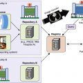
Computed tomography (CT), with its continually advancing technology, allows rapid scanning of critically injured patients detailing internal injuries from head to toe, assessing traumatic brain, cervical spine, chest, abdomen, and pelvic injuries—a one-stop shop for traumatic injury diagnosis. Computed tomography angiograms can reveal vascular injuries and active bleeding requiring acute intervention. Performing whole-body multidetector computed tomography (WBMDCT) early in the initial care of polytrauma patients with multisystem injury (injury severity score ≥ 16) significantly increases the probability of survival. This result is achieved because WBMDCT is a comprehensive diagnostic test that quickly identifies all major injuries so that the trauma team can optimize treatment and reduce missed injuries.
At our institution, 40- and 64-slice CT scanners are used for WBMDCT examinations ( Tables 11-1 and 11-2 ). The examination begins with a non–contrast-enhanced head CT scan to assess for intracranial injuries, including hemorrhage or herniation. After the head CT scan, if there is no clear clinical indication of shoulder girdle injury, the patient’s arms are then raised above the head, placed alongside the neck. This positioning provides the best overall image quality for the single scanning run through the head, neck, chest, and abdomen/pelvis with the least total radiation. Other arm positions that can be used in patients with shoulder girdle injury include placing the arms alongside the torso or ventrally over the chest. In both these positions, lifting the arms on pillows can reduce artifact arising from the arms and decrease total exposure.
| Parameter | Dry Head | Arterial Phase | Portal Venous Phase |
|---|---|---|---|
| Patient positioning | Arms fully extended adducted | Affected arm fully abducted | Affected arm fully abducted |
| Detector collimation and configuration (mm) | 16 × 0.625 | 64 × 0.625 | 32 × 1.25 |
| Pitch | 0.625 | 0.656 | |
| Rotation time (sec) | 1.5 | 0.5 | 0.5 |
| kV | 120 | 120 | 120 |
| Current (mA) | 350 | 250 | 250 |
| Area scanned | Skull base through the vertex | Circle of Willis through the lesser trochanters | Diaphragms to the iliac crests |
| Contrast volume (mL) | — | 100 | — |
| Contrast injection rate | — | 60 mL at 6 mL/sec 40 mL at 4 mL/sec | — |
| Scan delay (sec) | — | 18 ∗ | 60 |
| Source axial images (mm) † , ‡ | 1.25 | 2 × 1 | 2 × 1 |
| Reconstruction filter | Brain | Soft tissue | Soft tissue |
| Diagnostic axial images to PACS ‡ (mm) | 5 × 10 | 3 × 3 | 3 × 3 |
| Sagittal MPR ‡ (mm) for chest, abdomen and pelvis | 4 × 3 | 4 × 3 | |
| Coronal MPR ‡ (mm) for chest, abdomen and pelvis | 4 × 3 | 4 × 3 | |
| Thin-section axial images to independent workstation (mm) | 2 × 1 | 2 × 1 |
∗ For patients less than 50 years old.
† Source axial images used to construct all routine diagnostic images.
| Parameter | Face | Cervical Spine | Thoracic/Lumbar Spine |
|---|---|---|---|
| Source axial images (mm) † , ‡ | 1 × 0.5 | 1 × 0.5 | 1.5 × 0.75 |
| Reconstruction filter | Bone | Bone | Bone |
| Diagnostic axial images to PACS ‡ (mm) | 1 × 0.5 | 1 × 0.5 | 2 × 1 |
| Sagittal MPR ‡ (mm) | 2 × 2 | 1 × 0.5 | 2 × 1 |
| Coronal MPR ‡ (mm) | 1 × 0.5 | 1 × 0.5 | 2 × 1 |
| Thin-section axial images to independent workstation (mm) | 1 × 0.5 | 1 × 0.5 | 1.5 × 0.75 |
† Source axial images used to construct all routine diagnostic images.
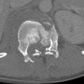
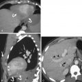
The patient is initially scanned from the vertex of the head through the inferior pubic rami in the arterial phase to assess for nonbleeding vascular injuries and acute bleeding usually best seen in this phase; this also contributes to detection of nonvascular injury ( Fig. 11-1 ). A portal venous phase is obtained about 60 seconds after the contrast injection from the diaphragm to the iliac crest to facilitate the diagnosis of nonvascular parenchymal injuries in the solid organs, especially given the often heterogeneous parenchymal enhancement seen in the arterial phase, particularly the spleen ( Fig. 11-2 ). This dual-phase imaging approach optimizes detection of both vascular and nonvascular injury (see Solid Intraperitoneal Organ Injury ).


Axial images of the head CT are immediately sent to the picture archiving and communication system (PACS) for rapid interpretation of traumatic brain injuries. The axial cervical spine images are reconstructed with a smaller field of view from the same data set to provide detail of bony and vascular structures. A bone filter is also used to provide detailed high-resolution images of the osseous structures. Sagittal and coronal multiplanar reformats are routinely performed to provide orthogonal axes that improve visualization of some injures based on their orientation. Imaging the cervical spine with intravenous contrast material as part of the WBMDCT serves as a screening technique to identify carotid or vertebral artery injuries not infrequently seen in patients with no risk factors for these injuries. This technique does not limit the diagnosis of cervical spine fractures.
Axial images of the chest, abdomen, and pelvis are reconstructed as single continuous coronal and sagittal images to facilitate “seamless” assessment of the thoracoabdominal region, given the continuity of these body regions, and to decrease radiation exposure compared to scanning these body regions separately with overlapping fields of coverage ( Fig. 11-3 ). Sagittal and coronal multiplanar reformatted images of the chest, abdomen, and pelvis are routinely generated for both the arterial and portal venous phase scans, and dedicated targeted studies of the thoracic and lumbar spines, often requested, are created from the original data set.

Computed Tomography Protocols
Protocol for Assessing Extremity Vascular Injuries
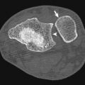
Vascular injuries constitute 3% of trauma cases with the potential for significant morbidity. Penetrating injuries from gunshot or stab wounds are the most common source of vascular injury producing disruption of the vessel wall via direct impact injury or blast effect ( Fig. 11-4 ). The most common cause of blunt vascular injury is crushing that can produce intimal flaps with secondary thrombosis or complete disruption of the vessel and thrombosis. Box 11-1 shows indications for extremity CT angiography (CTA).

Asymmetric pulses
Nonexpanding hematoma
Proximity of the wound to major vessels
Peripheral neurologic deficit
History of arterial bleeding at the scene
Abnormal ankle-brachial index
Typically the affected upper extremity can be raised above the patient’s head to reduce beam-hardening artifact in the absence of shoulder girdle injury (see earlier discussion). The lower extremities may also be evaluated at the same time given adequate table length. When studying the lower extremities, a larger than typical intravenous contrast bolus will be required to ensure adequate vascular opacification ( Table 11-3 ). Intravenous contrast should be injected on the contralateral side of a suspected upper extremity injury. This technique helps avoid artifact arising from the contrast bolus that can obscure injuries in the adjacent arteries or soft tissues.
| Parameter | Upper Extremity | Lower Extremity |
|---|---|---|
| Patient positioning | Affected arm fully abducted | — |
| Detector collimation and configuration (mm) | 40 × 0.625 | 64 × 0.625 |
| Pitch | 1.076 | 1.076 |
| Rotation time (sec) | 0.5 | 0.5 |
| kV | 120 | 120 |
| Current (mA) | 200 | 230 |
| Area scanned | Mid thorax through fingertips | Mid abdomen to the toes |
| Contrast volume (mL) | 100 | 125 |
| Contrast injection rate | 4 mL/sec | 4 mL/sec |
| Scan trigger threshold (HU) † | 120 | 120 |
| Source axial images (mm) ‡ , § | 1 × 0.5 | 1.5 × 0.75 |
| Reconstruction filter | B (soft tissue) | B (soft tissue) |
| Diagnostic axial images to PACS § (mm) | 2 × 1 | 2 × 1 |
| Sagittal MPR § (mm) | 5 × 2 MIP | 5 × 2 MIP |
| Coronal MPR § (mm) | 5 × 2 MIP | 5 × 2 MIP |
| Thin-section axial images to independent workstation (mm) | 1 × 0.5 | 1.5 × 0.75 |
† Bolus Pro Triggering System (Philips Medical Systems) with region of interest at distal ascending aorta.
‡ Source axial images used to construct all routine diagnostic images.
Protocol for Follow-up of Solid Organ Injury
Controversy persists regarding the merits of routine CT follow-up of solid organ injuries before discharge to document healing and exclude injury progression or complications. Indications in our practice for follow-up CT include clinical deterioration and initial diagnosis of high-grade injury. A follow-up CT typically is obtained between 48 to 72 hours after admission. The protocol will vary if angiographic intervention has been previously performed to treat the injury. Contrast material used during the angiographic procedure can extravasate into or around the injured organ and mimic active hemorrhage on a follow-up contrast-enhanced CT. Therefore it is important to document the presence of any previously extravasated angiographic contrast material by performing a non–contrast-enhanced CT in patients who have had recent angiography before performing a follow-up CTA. This will optimize distinction of previously extravasated contrast from continuing bleeding. The protocol used is shown in Table 11-4 .
| Parameter | Arterial Phase | Portal Venous Phase |
|---|---|---|
| Patient positioning | Affected arm fully abducted | Affected arm fully abducted |
| Detector collimation and configuration (mm) | 40 × 0.625 | 64 × 0.625 |
| Pitch | 0.671 | 1.093 |
| Rotation time (sec) | 0.5 | 0.5 |
| kV | 120 | 120 |
| Current (mA) | 250 | 300 |
| Area scanned | Diaphragm to the lesser trochanters | Diaphragm to the iliac crests |
| Contrast volume (mL) | 100 | — |
| Contrast injection rate | 4 mL/sec | — |
| Scan trigger threshold (HU) ∗ | 120 | — |
| Scan delay (sec) | — | 70 sec |
| Source axial images (mm) †,‡ | 0.9 × 0.45 | 1.5 × 0.75 |
| Reconstruction filter | B (soft tissue) | B (soft tissue) |
| Diagnostic axial images to PACS ‡ ( mm) | 3 × 3 | 3 × 3 |
| Sagittal MPR ‡ (mm) | 5 × 3 MIP | 4 × 3 |
| Coronal MPR ‡ (mm) | 5 × 3 MIP | 4 × 3 |
| Thin-section axial images to independent workstation (mm) | 0.9 × 0.45 | 0.9 × 0.45 |
∗ Bolus Pro Triggering System (Philips Medical Systems, Cleveland, Ohio) with region of interest at distal ascending aorta.
† Source axial images used to construct all routine diagnostic images.
Protocol for Bladder Injury
Bladder injuries are seen in approximately 2% of blunt trauma patients involving the abdomen and pelvis and often involve concurrent pelvic fractures. Injury to the bladder is often related to how distended the bladder is at the time of injury. Gross hematuria is the most common clinical finding. Bladder ruptures are intraperitoneal in 25%, extraperitoneal in 62%, and combined in 12% of cases. Dedicated evaluation of the bladder can be conducted at the conclusion of the WBMDCT examination and is advised in the setting of pelvic fractures with or without gross hematuria.
If CT cystography is being performed, the bladder should be emptied and continually drained by an indwelling Foley catheter before the scan is started. After the portal venous phase is obtained, the bladder should be filled with a water-soluble iso-osmolar radiopaque contrast (35 mL of Omnipaque 350 diluted in 450 mL of sterile water). The contrast is instilled under gravity through the Foley catheter from a bag of contrast 1 m above the CT table. The pelvis is then imaged when the bladder is full (approximately 300 mL) or the column of contrast stops flowing. Axial views are obtained at a slice thickness of 0.9 mm for high resolution with sagittal and coronal reformations ( Table 11-5 ). Postvoid images are routinely obtained in an attempt to see possible injuries posterior to the bladder. Given the superior ability of multidetector computed tomography (MDCT) to assess the soft tissues surrounding the bladder, there is no need to image the pelvis with CT after emptying the bladder unless there is the rare question of contrast retained in the bladder versus extravasated contrast.
| Parameter | |
|---|---|
| Detector collimation and configuration (mm) | 64 × 0.625 |
| Pitch | 0.984 |
| Rotation time (sec) | 0.75 |
| kV | 120 |
| Current (mA) | 250 |
| Area scanned | Iliac crests to the ischial tuberosities |
| Source axial images (mm) † , ‡ | 0.9 × 0.45 |
| Reconstruction filter | B (soft tissue) |
| Diagnostic axial images to PACS ‡ (mm) | 4 × 3 |
| Sagittal MPR ‡ (mm) | 4 × 3 |
| Coronal MPR ‡ (mm) | 4 × 3 |
| Thin-section axial images to independent workstation ‡ (mm) | 0.9 × 0.45 |
∗ Parameters are used for the initial non-filled and full bladder.
† Source axial images used to construct all routine diagnostic images.
Renal injuries, such as lacerations, extending to the renal collecting system may cause hematuria. Lacerations disrupting the collecting system may lead to complications associated with urine leaks, which can be easily managed with nephroureteral stents. These injuries may be easily missed on the arterial and portal venous phases of the whole-body CT given the lack of radiopaque contrast within the renal collecting system. It is advised that patients with renal injuries extending to the renal collecting system have additional imaging through the kidneys at least 5 minutes after the injection of contrast if the study is being actively monitored or return to the CT scanner for delayed imaging if a question of collecting system injury is raised by review of the initial whole-body scan.
Oral and Rectal Contrast Material
Protocol for Blunt Trauma
Intravenous contrast is routinely administered to patients undergoing CT after trauma to improve recognition of both vascular and parenchymal injury. However, the use of oral contrast for admission CT examinations has decreased significantly over the past few years. The routine availability of high spatial resolution axial and reformatted images, increased familiarity with CT signs of bowel and mesenteric injury, and the low sensitivity of spilled gastrointestinal contrast with full-thickness bowel injury are some reasons for this development. Although oral contrast aspiration is also mentioned as a contraindication for its use, this is in fact an extremely rare event. Computed tomography without oral contrast can typically show subtle bowel wall thickening, minimal pneumoperitoneum, direct defects in the bowel wall, a small quantity of intraperitoneal free fluid, and small mesenteric contusion or hematomas.
At our institution, patients needing a repeat CT of the abdomen and pelvis for indeterminate initial CT findings of bowel or mesenteric injury, isolated free intraperitoneal fluid beyond a trace amount without a clear source, or clinical deterioration possibly related to an abdominal source following a negative admission CT are reimaged with inclusion of oral contrast material ( Fig. 11-5 ). A total volume of 600 mL of oral contrast material (50 mL Omnipaque 300 diluted in 950 mL of water) is given in two equal doses orally or per orogastric tube, the first about 30 to 45 minutes before and the second immediately before performing the scan.

Protocol for Penetrating Trauma
In the setting of penetrating trauma to the torso (entry site between nipple line and upper third of thigh), a triple-contrast MDCT examination of the chest, abdomen, and pelvis should be performed. The triple-contrast technique includes the use of iodinated intravenous contrast and water-soluble oral and rectal contrast material. The patient is scanned using the solid organ injury protocol (see Table 11-4 ) following administration of both oral (600 mL in two divided doses) and 1 to 1.5 L of rectal contrast (50 mL Omnipaque 300 diluted in 950 mL of water) through a rectal tube as an enema. The enema is administered under gravity (the enema bag is 1 m above the CT table) before performing the scan in the CT suite. Patients requiring urgent CT on admission may be scanned with a single dose of oral and rectal contrast material.
Special Considerations
Protocol for Pregnant Patients
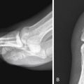
Blunt trauma may complicate up to 7% of pregnancies and is a leading cause of maternal death, with the majority of injuries sustained in motor vehicle collisions. Penetrating trauma as a result of domestic violence or accidental gunshot wounds account for as many as 36% of maternal deaths. Although there is always concern for radiation exposure to the fetus, this should not impede the performance of radiographic or CT examinations to evaluate life-threatening injuries sustained by the mother ( Fig. 11-6 ). In hemodynamically stable pregnant patients following major blunt trauma, WBMDCT should be used to screen for injuries. Automatic exposure control (AEC) should be used to reduce radiation dose. A formal obstetric ultrasound (US) examination is also performed in hemodynamically stable patients by an experienced physician or ultrasonographer to document the age of the fetus and to assess viability and placental integrity.

Protocol for Obese Patients
The CDC, National Institutes of Health, and World Health Organization define obesity as a body mass index of 30 or more, which is calculated by dividing the weight (in kilograms) by the square of the height (in meters). The prevalence of obesity among adults in the United States has increased steadily since 1985, when the CDC conducted its first Behavioral Risk Factor Surveillance System survey. In 2006 more than 72 million Americans 20 years or older were obese with a slightly higher prevalence among women (35.5%) than men (33.2%).
The most common technical difficulties experienced with obese patients are the bore size of the CT scanner and the weight limit of the scanner table. This has been accommodated by CT manufacturers now offering CT tables with weight limits approaching 700 pounds and selected vendors increasing bore size with the largest aperture of 90 cm and a 70-cm acquired field of view.
The most common artifact encountered in the CT images of obese patients is photon starvation. Increased body fat raises photon attenuation, resulting in insufficient photon transmission to the detectors. This in turn results in excessive quantum mottle, reduced contrast-to-noise ratio, and streak artifact. Increasing the milliamperes and decreasing the pitch increases the number of photons transmitted to the detectors, decreasing the photon starvation artifact. The peak kilovoltage (kVp) can also be increased to raise the energy of the photons to better penetrate the soft tissues. The use of 140 kVp is advised for morbidly obese patients (body mass index ≥ 40) to improve the contrast-to-noise ratio in soft tissues. The use of 120 kVp is advised for CTA in most obese patients to optimize iodine-induced attenuation. Slice thickness can be widened to increase the number of photons used to produce each image. Iterative reconstruction algorithms also reduce noise created by diminished detector exposure. Beam-hardening artifact may also be encountered when obese patients lay flat and large breasts or subcutaneous fat falls to the side, creating an asymmetric profile and leading to beam hardening and photon starvation artifacts in lateral CT projection, which is exacerbated by the bowtie filter effect (see Chapter 1 ). This may be overcome by bundling or wrapping the patient in sheets or CT restraint devices to reduce artifact by providing a symmetric profile of excess soft tissues ( Fig. 11-7 ).

With the increase in milliamperes and kVp to obtain diagnostic images, obese patients receive higher radiation doses than nonobese patients. Automatic exposure control may be used to help reduce radiation dose to the obese patient. However, special attention needs to be given to specific protocols that include AEC. The maximum milliamperes must be restricted, otherwise AEC will automatically increase tube output to compensate and may result in very large radiation doses, the opposite of what is desired when trying to reduce the patient’s overall radiation exposure.
Sonography
- Alexandra Platon
- Pierre-Alexandre Poletti
Imaging plays a key role in the screening of blunt abdominal trauma patients because clinical examination is insufficient to rule out a major intra-abdominal traumatic injury. The imaging method to be used for the screening of traumatic intra-abdominal injuries should be adapted to the available institutional imaging facilities and to the hemodynamic status of the patient. Imaging a polytrauma patient should take into consideration the balance between the quality of the examination and the time required to obtain these images to fit with the concept of “the golden hour”: the shorter the time elapsed between trauma and treatment, the higher the chances of survival. Thus, because time constraint is a major issue in hemodynamically unstable patients, the imaging management must be performed as fast as possible, for immediate depiction of the life-threatening condition. The situation is different in a hemodynamically stable patient, with sufficient time to obtain a more detailed examination. In this case the main concern is to select the most appropriate imaging algorithm and to avoid missing subtle or potentially life-threatening injuries, which may become apparent only in a delayed fashion.
In this section we will present several aspects of the current imaging methods used for the initial triage and diagnostic work-up of blunt abdominal trauma patients.
Ultrasonography
Focused Assessment Sonography for Trauma
In clinical practice, focused assessment sonography for trauma (FAST) consists of regarding and using US as a rapid diagnostic test for depiction of free fluid only. This technique can be performed by emergency medical staff with a relatively limited level of training in US, including nonradiologist physicians or surgeons.
FAST examination is realized by using a sector probe with a frequency in the range of 2.5 to 5 MHz, according to the patient’s morphologic characteristics.
To check for the presence of free peritoneal fluid, the technique of FAST examination consists of assessing at least three abdominal regions:
- 1.
The right upper quadrant, for visualization of the hepatorenal recess (Morison pouch), where free fluid may freely accumulate from the upper abdomen and from the right pericolic gutter because there is no ligament to hinder fluid movement. The detectability of fluid in the Morison pouch may be improved, when feasible, by the Trendelenburg position.
- 2.
The left upper quadrant, to assess the presence of perisplenic fluid. Both the splenorenal and subphrenic areas should be carefully examined.
- 3.
The rectovesical recess in males and the Douglas pouch in females, which are the most dependant areas of the pelvis. A full bladder is required to optimize the depiction of free fluid in this region.
Views of the right and left paracolic gutters are also considered as part of the FAST examination by some authors, but their added value has not been demonstrated yet.
The presence of pleural fluid will be sought during the examination of the right and left upper quadrants.
It is also classically recommended that a subxiphoid view be obtained to assess for the presence of pericardial fluid. However, the actual benefit of doing so is not well established, and it may also be a source of overdiagnosis.
Focused Assessment Sonography for Trauma Findings
Aspect
Intraperitoneal blood may have a different appearance at US. It may vary according to the quantity of blood and to the delay elapsed between the onset of bleeding and the examination ( Fig. 11-8 ). Blood may appear completely anechoic, anechoic with some internal echoes, or as an echogenic mass, corresponding to a clotted hematoma. These various forms may also coexist.

Where as a large quantity of free fluid is easily detected as a hypoechoic area in all peritoneal recesses, with floating bowel loops, a small quantity of blood is more difficult to assess and may be detected as a sliver of anechoic fluid in the Morison pouch, in the left subphrenic space, and/or in the pelvis.
Minimum Blood Volume to be Detected
The minimum amount of blood to be detected by US is impossible to assess because it will depend not only on the volume of blood, but also on its echogenicity (free fluid or clotted blood) and on the skill of the operator. It has been reported that the minimum quantity of free peritoneal fluid that can be detected by US in the Morison pouch is 250 mL, although a minimum of 620 mL would be required to be depicted by the majority of the operators.
Quantification of Free Fluid
The estimation of the quantity of free intraperitoneal fluid as small, moderate, or large is important and is subject to interpersonal variability. However, such quantification may be useful for the triage of patients when correlated to the hemodynamic status. The detection of a large quantity of free peritoneal fluid in a patient who is hemodynamically unstable will certainly justify an immediate laparotomy, whereas a small quantity of peritoneal fluid in the same patient will alert the clinician to look for another source of bleeding. Some authors proposed various scoring systems to more precisely estimate the quantity of free peritoneal fluid, according to its depth and location. However, these scores have not been validated by large series and are currently not used in most trauma centers.
Training of the Operator for Focused Assessment Sonography for Trauma
The wide majority of FAST examinations in the United States are now performed by nonradiologists in both university and community hospitals.
The minimum training required for a nonradiologist to become proficient in FAST is one of the more controversial topics in trauma US. There is no consensus or standard guidelines for the minimum number of FAST examinations that should be performed under supervision before a surgeon or emergency physician can be considered trained in this technique. This number fluctuates from 10 to 200 according to the various authors, institutions, or medical associations. This variability is easy to understand when considering the fact that the skill to depict a large quantity of free fluid will be lower than that necessary to depict a sliver of free fluid. Many authors consider that a minimum of 30 proctored examinations is necessary to become proficient in FAST, taking into consideration that the trainee must be confronted with a sufficient number of positive cases.
Value of a Focused Assessment Sonography for Trauma Examination
The practical value of a FAST examination depends on the hemodynamic status of the patient. In a hemodynamically unstable patient, positive FAST results mandate laparotomy, following the recommendations of the 1997 International Consensus Conference in Baltimore. When the FAST results are negative, the clinician will look for a nonabdominal source of bleeding.
In a hemodynamically stable patient the value of the FAST examination will be more dependent on the existing resources of a given institution, and the guideline should be adapted in consequence. No general rules can be enacted. Thus it is even questionable whether a FAST examination should be performed in a stable patient who will undergo a CT examination anyway. In this situation, performing FAST may be helpful for choosing the priority order for CT, when many patients are managed simultaneously. Positive FAST results are usually considered an indication for performing an abdominal CT.
Although negative CT results are sufficient to rule out an intra-abdominal injury, negative FAST examination results alone cannot do so and must therefore be integrated in the clinical situation to be correctly interpreted. Thus, in alert patients who underwent minor blunt abdominal trauma, without any other reason to perform a CT, negative FAST examination results may be useful, in addition to normal clinical examination results and normal biologic parameters, to decide whether the patient can be discharged without performing a CT scan. Depending on the clinical scenario, serial negative FAST examination results along with 12 hours of clinical observation have been advocated before discharging a patient without performing CT.
Pitfalls
The subphrenic space may be difficult to screen due to the accumulation of bowel gas in the splenic flexure. However, this area should be carefully scrutinized because a small quantity of fluid will preferentially accumulate in this space rather than in the splenorenal interface.
A small quantity of free fluid may only be depicted in the Douglas pouch (rectovesical space in males), which corresponds to the most dependent space of the abdomen. A proper analysis of this requires a distended bladder. If the bladder is empty, FAST may miss a small amount of free fluid.
Clotted blood may appear hyperechoic and thus be overlooked or misinterpreted as normal abdominal content.
False-positive FAST results are much less common than false-negative ones. Fat may sometimes appear hypoechoic and mimic fluid, especially between the kidney and the liver. Similarly, normal pericardial fat may often be considered as pericardial effusion. Intraintestinal fluid content may also be falsely interpreted as free fluid when the operator does not pay attention to the bowel movements. The detection of normal fluid in the Douglas pouch in a woman in the middle of her menstrual period may be source of diagnostic dilemma and should be integrated in the clinical setting. Similarly, a preexisting ascites in a trauma patient may be misinterpreted as hemoperitoneum.
A large percentage of intra-abdominal organ injuries (up to 34%) are not associated with free peritoneal fluid and therefore remain undetectable by FAST. Up to 16.5% of these lesions have been considered life threatening because they required surgery or embolization. Besides, the limitation of FAST for detecting free fluid originating from bowel and mesenteric injuries has also been documented, with a sensitivity not exceeding 44%.
Blood associated with retroperitoneal injuries (kidney, pancreas, vessels) is classically missed by FAST because it does not appear hypoechoic and therefore remains undistinguishable from retroperitoneal fat.
Parenchymal Analysis
Parenchymal injuries may have various presentations at direct US examination ( Fig. 11-9 ). An acute liver injury classically appears as a hyperechoic area when compared to the normal parenchyma; it may also be detected as a heterogenous or hypoechoic structure, depending on the time elapsed from the trauma and the severity of the injury. In the spleen and kidney, injuries are usually hypoechoic or heterogenous, with possible foci of cysticlike lesions and disorganization of the normal parenchyma.

The capsule of the organ must be scrupulously scrutinized for the presence of hypoechoic or hyperechoic layers, corresponding to hematoma. Doppler examination does not clearly improve the detection of parenchymal injuries when compared to B mode alone and is therefore not recommended in this setting. However, a Doppler examination may be useful to detect an occlusion of a renal artery.
To improve the sensitivity of US to suggesting an intra-abdominal injury, it is recommended, in addition to the search for free peritoneal fluid, to systematically analyze the parenchyma of solid intra-abdominal organs. Doing so requires a higher level of prior training in abdominal US, which should be achieved in a radiologic ward, when compared to limiting the screening to a sole FAST examination. However, the added value of complete US examination to confirming the suspicion of organ injury with regard to free-fluid analysis only is subject to controversy. About 50% of CT-proven organ injuries remain undetectable at parenchymal examination by US. When abdominal free fluid is detected in an unstable patient, it is probably of no clinical benefit to spend additional time searching for the source of bleeding by US.
Contrast-Enhanced Ultrasonography in Abdominal Trauma
Value and Limitations of a Contrast Ultrasonographic Examination
Contrast-enhanced US has been reported to be much more efficient than B-mode US only for the depiction of liver, spleen, and kidney injuries ( Fig. 11-10 ) . The sensitivity for depiction of traumatic organ injuries is classically between 50% and 80% at US, and between 90% and 94% after administration of ultrasound contrast media. Contrast US examination requires specific training in this technique and can therefore be performed only by a skilled operator. Contrast-enhanced US should be performed in optimal conditions and is completed in approximately 10 to 15 minutes. These constraints prevent this technique from being used at a patient’s admission. However, it can play an interesting role in ruling out a solid organ injury in the follow-up of a patient who underwent minor abdominal trauma, with no clinical indication for undergoing a CT scan. Contrast-enhanced US has also been reported useful for follow-up of solid organ injuries detected by CT. However, this technique is still limited by its inability to depict bowel injuries and by the cost of US contrast agent, which is similar to that of CT contrast media.

Contrast-enhanced US has been reported useful for the depiction of traumatic vascular injuries. Thus it can play an interesting role in the screening of delayed splenic pseudoaneurysms, which may appear some days after trauma and are considered a cause of failure of nonoperative management. A contrast-enhanced US examination that is positive for the presence of a pseudoaneurysm mandates an angiographic embolization.
Technique
Second-generation US contrast agents consist of stabilized microbubbles filled with an inert innocuous gas and are characterized by both stability and resistance to pressure. Unlike the first generation of contrast agents, the bubbles are not massively destroyed during their first pass into the pulmonary vascular microcirculation. Thus they can be used during several minutes after a single intravenous bolus. The US contrast agent is eventually eliminated through the pulmonary route and is thus innocuous for the kidney.
An initial analysis of parenchyma is first performed on standard B-mode imaging. Then the operator switches on a specific mode for contrast media (such as a pulse inversion harmonic mode) with a reduced mechanical index. The contrast agent is then injected intravenously, using a 20-gauge catheter placed into an antecubital vein, followed by a 10-mL flush of saline water. The maximal parenchymal enhancement is obtained about 1 minute after injection for the liver and spleen and earlier (20 to 30 seconds) for the renal cortex. Solid organ injuries appear as deep hypoechoic (nonenhancing) areas, when compared to the hyperechoic enhancement of the normal surrounding parenchyma. A focal pooling of contrast medium within the splenic parenchyma during the arterial phase, with enhancement similar to the splenic artery, surrounded by a normally enhancing or nonenhancing (injured) parenchyma, is highly suggestive of a pseudoaneurysm ( Fig. 11-10 F).
Multidetector Computed Tomography Imaging
Multidetector CT has become a key diagnostic tool for the management of polytrauma patients and is now equipping most emergency centers. It allows a rapid and accurate assessment of the whole body. Computed tomography is not only valuable to get a thorough assessment of soft and bony structures, but also plays a key role in determining the need for surgery or nonoperative management of intra-abdominal injuries. In a polytrauma patient CT is useful for obtaining a detailed analysis of multiple lesions. In patients who underwent minor trauma, CT is necessary to rule out an injury. Indeed, normal abdominal CT results have been considered sufficient to safely discharge a patient with no other reason to be hospitalized. Performing a systematic CT scan in every abdominal trauma patient will expedite the work flow in the ED and has been reported to be cost-effective by saving the institution’s resources. On the other hand, doing so raises the problem of exposing to radiation doses and contrast media some patients who could otherwise have been managed by US and clinical observation only. This dilemma between overuse of CT in mild trauma patients and improving the work flow in a busy emergency center is unresolved; specific guidelines should therefore be tailored to every institution.
A follow-up CT scan is usually indicated for the monitoring of nonoperative management in patients with major abdominal organ injuries and for the depiction of complications after abdominal surgery.
Magnetic Resonance Imaging
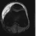
Magnetic resonance imaging (MRI) plays a limited role in abdominal trauma patients because it is technically difficult to perform in an acute setting. Magnetic resonance imaging is sometimes used as a complement to CT in a limited number of well-targeted indications. Thus MRI has been reported useful for showing the integrity of hemidiaphragms and to demonstrate the herniation or entrapment of abdominal contents when CT images are ambiguous.
In a liver trauma patient with suspicion of bile leak in the peritoneum ( Fig. 11-11 ), MRI may be useful for confirming a lesion of the biliary ducts and to depict the exact site of the injury, allowing optimal management (drainage or surgical repair). In this setting, MRI must be used with injection of hepatobiliary-specific contrast agents.

In pancreatic injuries the diagnosis of pancreatic transection is often difficult to ascertain on CT images. Information about the presence and location of a pancreatic duct rupture is of paramount importance to determining the proper treatment (i.e., surgery in proximal disruptions, drainage in distal injuries) and to preventing complications. Magnetic resonance imaging is now used as a noninvasive alternative to endoscopic retrograde cholangiopancreatography (ERCP) to assess the integrity or the disruption of the pancreatic duct. Unlike ECRP, MR pancreatography ( Fig. 11-12 ) allows visualization of the pancreatic duct beyond the injury site.

Solid Intraperitoneal Organ Injury
- Alexis Boscak
- Kathirkamanathan Shanmuganathan
The spleen and liver are the two most frequently injured organs after blunt trauma to the abdomen, most commonly caused by motor vehicle collision, fall, assault, or sports or workplace accident. Exsanguinating hemorrhage may result from disruption of either of these highly vascular organs; if there is hemoperitoneum after blunt abdominal trauma, spleen and liver injuries should sought initially. Imaging protocols for investigation of spleen and liver injuries are almost identical. Both organs are best evaluated in the acute setting by contrast-enhanced CT with arterial, portal venous, and, in some cases, delayed phase imaging, which play similar roles in the assessment of both organs. Blunt splenic and hepatic injuries may require emergent laparotomy for surgical therapy, generally in the setting of hemodynamic instability, or may be amenable to nonoperative management with or without angiographic intervention. Splenectomy provides definitive control of life-threatening splenic hemorrhage, although with a lifetime risk for overwhelming postsplenectomy sepsis, whereas surgical management of severe liver injury is necessarily more complex. Liver trauma is also complicated by the possibility of coexistent biliary injury. Treatment of both splenic and hepatic blunt trauma has evolved over the past several decades toward conservative nonoperative management for a majority of cases, even with high-grade injuries. This trend is concurrent with increased use of CT as the primary diagnostic imaging modality after blunt abdominal trauma, allowing improved diagnosis and injury characterization, which not only facilitates appropriate selection of patients for initial operative versus nonoperative therapy, but also allows patients undergoing conservative management who show signs of deterioration to be readily and accurately reevaluated without requiring immediate recourse to laparotomy. There are many similarities between the imaging findings after blunt splenic and hepatic injury and some important differences. The posttrauma imaging evaluation of each of these organs is addressed in separate sections to follow.
Blunt Splenic Injury
Splenic Anatomy and Traumatology
Although relatively small and sheltered within the left upper quadrant, the spleen is a delicate organ consisting of soft, friable, and extremely vascular parenchyma constrained by a thin capsule. The spleen receives as much as 5% (200 mL/min) of the cardiac output and may contain as much as 500 mL of blood at a time. The spleen is primarily perfused by the splenic artery, which also gives rise to pancreatic branches, several short gastric arteries, and, in some cases, a posterior gastric artery, as well as having an anastomosis with the left gastroepiploic (left gastro-omental) artery near the splenic hilum. The intrasplenic arterioles, which are surrounded by lymphoid tissue constituting the splenic white pulp, are end vessels that may feed into the intrasplenic red pulp or directly into venous sinuses. Venous outflow is through the main splenic vein to the portal vein. Although primarily intraperitoneal, the spleen has limited extraperitoneal bare areas at its vascular hilum and along the confluence of its peritoneal attachments. The spleen is suspended within the left upper quadrant by the partially continuous phrenicosplenic, gastrosplenic, and splenorenal ligaments and rests upon the phrenicocolic ligament below. Unless unusually long, the splenic vascular pedicle affords the organ only limited mobility. The nonenlarged spleen does not generally protrude below the costal margin, but a pathologically enlarged spleen may be significantly exposed, in addition to being abnormally fragile. Displaced fracture of the overlying ribs may result in splenic laceration. Direct compression and acceleration/deceleration shear forces are the other major mechanisms of splenic disruption in blunt trauma. The spleen is the only injured abdominal organ in approximately 60% to 75% of cases, although extra-abdominal injuries may be present in up to 80% of patients with blunt splenic injury.
Splenic Trauma Imaging Modalities and Protocols
Computed Tomography
Computed tomography is the primary modality for definitive evaluation of the spleen after blunt trauma. Contrast enhancement is necessary for optimal diagnostic performance, rendering splenic parenchymal injuries, which can be inconspicuous on noncontrast CT, visible as defects within the otherwise enhancing organ. Such injuries are best depicted in the portal venous phase during which splenic parenchymal enhancement is most homogeneous; the heterogeneity of the arterial phase spleen and decreased parenchymal attenuation in delayed phases (3 to 5 minutes post injection of intravenous contrast material) make these unsuitable for primary diagnosis of splenic parenchymal injury. Arterial phase imaging, however, can demonstrate contained splenic vascular injuries (pseudoaneurysms and arteriovenous fistulas) that may become imperceptible in later phases. Active bleeding can appear in any phase but may be indistinguishable from contained vascular injury unless CT images are acquired in more than one phase. For this reason, delayed imaging may be of value if a contrast “blush” is seen on a portal venous phase image, although late-phase CT is otherwise of limited utility for splenic evaluation. Some trauma centers routinely acquire portal venous phase images and perform immediate image review to determine whether or not delayed-phase images should be acquired; if necessary, dedicated arterial phase imaging would then require additional contrast agent injection. Other trauma centers use a primary dual-phase protocol including both arterial and portal venous phase CT imaging to optimize diagnosis of both vascular and parenchymal injuries on the admission study.
Other Modalities
Conventional radiography has limited value for evaluation of the abdomen after blunt trauma, although left lower rib fractures and displacement of the gastric air bubble from the left upper quadrant by a perisplenic hematoma can raise suspicion for splenic injury. FAST protocol US examination is limited to interrogation for perisplenic hemorrhage. Dedicated ultrasonographic imaging can certainly identify splenic parenchymal injuries but is highly operator dependent and can be time consuming. Magnetic resonance imaging is not routinely used in the setting of splenic trauma because of limited availability, increased imaging time, and restrictions on patient access and instrumentation imposed by safety considerations in the magnetic field. Because of increased use of CTA for diagnosis, catheter angiography after splenic injury is now primarily performed for therapeutic or prophylactic embolization.
Computed Tomography Findings in Acute Splenic Trauma
Computed tomography evaluation after acute blunt splenic trauma may identify various injuries, including splenic lacerations, parenchymal devascularization and infarction, hematomas, and vascular injuries, including uncontained active bleeding, as well as contained pseudoaneurysms and arteriovenous fistulas. These various lesions can all be diagnosed by contrast-enhanced CT, but their appearance and conspicuity vary in different phases; in some cases comparison between phases at the exact same anatomic location is necessary for accurate characterization.
Splenic Injuries
Lacerations
Lacerations are the most common traumatic injury of the spleen. On postcontrast CT, lacerations typically appear as linear or branching areas of abnormal low attenuation within the otherwise enhancing spleen. Lacerations are most conspicuous in the portal venous phase, when intact splenic parenchymal enhancement is most homogeneous and intense. Splenic lacerations may be partial or full thickness; through-and-through lacerations may be termed fractures ( Fig.11-13 ). Lacerations may or may not violate the splenic capsule; perisplenic hematoma suggests capsular disruption unless there is another likely source of hemorrhage. Laceration depth should be measured perpendicular to the splenic surface, although length can be assessed in any plane.

Infarctions
Sharply marginated geographic areas of splenic parenchymal nonenhancement typically extending to the capsule indicate devascularization resulting in infarction ( Fig. 11-14 ). Acute infarctions are edematous and may appear slightly bulky compared to intact portions of the spleen, whereas chronic infarctions become atrophic. Posttraumatic splenic infarctions can be of any size and number; it is useful to estimate the approximate percentage of splenic involvement by sizable infarctions. Hilar vascular injury or avulsion can result in total splenic infarction ( Fig. 11-15 ).


Hematomas
Acute hematomas from blunt trauma in and around the spleen show intermediate attenuation (40 to 70 HU). Hematomas are therefore slightly higher in attenuation than intact splenic parenchyma on noncontrast CT but are lower in attenuation than perfused splenic tissue on portal venous phase postcontrast CT. Splenic intraparenchymal hematomas may be distinguished from lacerations and infarcts by their typically rounded or ovoid shape with associated mass effect ( Fig. 11-16 ). Their maximum diameter should be reported. Splenic subcapsular hematomas accumulate at the splenic periphery but are constrained by an intact overlying capsule. They exert mass effect on the underlying splenic parenchyma, resulting in a characteristic crescentic or lenticular form ( Fig. 11-17 ). Maximal hematoma thickness should be reported. Perisplenic hematoma suggests underlying splenic injury with capsular disruption, but it must be kept in mind that hemoperitoneum from a remote source can also pool around the spleen. The term sentinel clot refers to the finding of the highest-attenuation hematoma near the site of bleeding in the setting of hemoperitoneum after blunt abdominal trauma. Perisplenic sentinel clot is therefore highly suspicious for underlying splenic injury ( Fig. 11-18 ).


Splenic Vascular Injuries
Blunt traumatic disruption of intrasplenic arteries can result in contained or uncontained arterial hemorrhage. Contained splenic arterial injuries include pseudoaneurysms and arteriovenous fistulas, whereas uncontained splenic arterial injury is manifest as frank active bleeding. Both types of injury are visible on postcontrast CT as extravasation of contrast-enhanced blood resulting in focal accumulation of contrast agent outside of intact vessel contours. The term contrast blush is commonly used for such lesions but is not specific for contained versus uncontained extravasation.
Uncontained active bleeding can be confidently diagnosed by single-phase CT when the extravasated blood tracks beyond the confines of the spleen, spilling into the peritoneal cavity ( Fig. 11-19 ). Uncontained intrasplenic active bleeding, however, can have the same appearance as contained intrasplenic arterial injury in a single phase, both appearing as foci of intrasplenic contrast extravasation, requiring multiphase CT for distinction.

Uncontained intrasplenic arterial bleeding ( Fig. 11-20 ) typically increases in volume and changes in form on sequentially obtained CT images, reflecting the ongoing active extravasation. The shape of the extravascular collection is often linear or irregular. Intrasplenic active bleeding may progress to extrasplenic (intraperitoneal) hemorrhage on subsequent phases during a single CT study. The extravasated enhanced blood is no longer in continuity with the vascular system, and so its attenuation does not wash out with time, although it may decrease by dilution into an accompanying hematoma.

Contained intrasplenic arterial injuries ( Fig. 11-21 ), which may include intrasplenic pseudoaneurysms as well as arteriovenous fistulas, appear as rounded or ovoid foci of contrast enhancement with attenuation matching (not less than 10 HU) that of intra-arterial blood, regardless of the acquisition phase, because these lesions remain in communication with the vascular system. Therefore sequential CT imaging of a contained intrasplenic arterial injury will demonstrate arterial phase enhancement followed by washout of contrast material synchronous with decreasing arterial attenuation. The lesion may become indistinguishable from surrounding parenchyma in the portal venous or delayed phases, depending on lesion size (which affects contrast transit). Early splenic venous enhancement in association with such a lesion is specific for arteriovenous fistula ( Fig. 11-22 ), but this finding is infrequently observed on CT and so these cannot usually be distinguished from pseudoaneurysms. The distinction is of limited clinical significance because catheter angiography is indicated in either case.


Splenic Injury Scoring
Numerous clinical, surgical, and radiologic systems exist for grading the severity of injury after trauma. Splenic injury grading scales allow the summarization of multiple features of injury as a single score. Such simplification facilitates rapid communication and is of value to subsequent research investigations but can also obscure clinically important detail. Although no currently available system can be relied upon as the sole determinant of patient management, splenic injury grading based on CT does factor into clinical decision making and is a component of many institutional trauma management protocols. Two different splenic injury grading scales are discussed in the following sections ( Table 11-6 ).
| AAST Grade | Laceration | Hematoma | Vascular Injury | CT Grade |
|---|---|---|---|---|
| I | <1 cm depth | Subcapsular < 10% surface area (AAST) or < 1 cm thick (CT) | — | 1 |
| N/A | — | Intraparenchymal < 1 cm diameter | — | 1 |
| II | 1-3 cm depth | Subcapsular 10%-50% surface area (AAST) or 1-3 cm thick (CT) | — | 2 |
| II | — | Intraparenchymal < 5 cm (AAST) or 1-3 cm (CT) diameter | — | 2 |
| III | >3 cm depth | Subcapsular > 50% surface area (AAST) or > 3 cm thick (CT) | — | 3 |
| III | — | Intraparenchymal > 5 cm (AAST) or > 3 cm diameter (CT) | — | 3 |
| III | — | Expanding or ruptured hematoma (AAST) or splenic capsular disruption (CT) | — | 3 |
| IV | laceration involving hilar or segmental vessel | — | >25% devascularization | N/A |
| V | — | — | Total devascularization | N/A |
| V | “Shattered spleen” | — | — | 4a |
| N/A | — | — | Contained or uncontained intrasplenic arterial injury (pseudoaneurysm, arteriovenous fistula, intrasplenic or subcapsular active bleeding) | 4a |
| N/A | — | — | Active intraperitoneal bleeding | 4b |
† Data from TraumaSource, The American Association for the Surgery of Trauma, http://www.aast.org/library/traumatools/injuryscoringscales.aspx#spleen .
American Association for the Surgery of Trauma Scale
The most widely used system for grading the severity of blunt splenic trauma is the American Association for the Surgery of Trauma (AAST) Spleen Injury Scale, which was developed to facilitate clinical investigation and outcomes research but is frequently used as a factor in determining clinical management in the acute setting. This is a surgical grading system but can (with some limitations) be applied based on CT findings after blunt splenic injury. The AAST splenic injury grade is determined by the depth of splenic lacerations, the surface area occupied by subcapsular hematomas, the maximum diameter of intraparenchymal hematomas, and the extent of devascularization (infarction), as well as the presence of expanding or ruptured hematoma; splenic fragmentation (“shattered spleen”) or complete devascularization constitutes the highest grade of injury. Multiple lacerations and hematomas advance the injury grade by one, up to grade III. Computed tomography findings of contained vascular injury or uncontained active bleeding do not directly affect the AAST grade. The primary advantage of using the AAST scale to grade splenic injury identified on CT is the near-universal familiarity of trauma surgeons with the AAST system, facilitating the goal of clear communication between the radiologist and the treating physician.
Modified Computed Tomography Classification
Despite its wide use by radiologists, the AAST scale was not designed as an imaging-based system, which limits its application to CT findings after blunt splenic trauma. Most importantly, the CT findings of contained vascular injury and uncontained active bleeding, which have clinical and prognostic significance, are not accounted for by AAST scoring. To address these shortcomings, alternative CT-based grading systems have been developed as CT has gained dominance as the primary modality for trauma imaging. A recently proposed system closely mirrors the AAST scale for grades 1 through 3 to maintain legibility but assigns the finding of intrasplenic vascular injury the new grade of 4a, and the finding of active bleeding into the peritoneal compartment the new grade of 4b. Splenic fragmentation (“shattered spleen”) is considered a grade 4a injury by this particular scale, which does not include a grade 5 and does not explicitly address the finding of parenchymal devascularization.
Fine Points of Splenic Injury Grading
Splenic injury grade is frequently used as one of the many factors determining clinical management after trauma, but it has limited predictive value regarding the need for specific interventions and the potential for failure of nonoperative management in any given case. The CT diagnoses of contained and uncontained arterial injury, which are included in the CT scale but not in the AAST scale, are proven risk factors for ongoing splenic hemorrhage requiring intervention and should be clearly described in the radiologist’s report, as well as being emergently communicated directly to the trauma team. Reporting a grade for splenic injury may improve the clarity of communication between the radiologist and the surgeon; however, because AAST and CT scale grades for a given splenic injury may not be concordant because of differences between the two systems, the radiologist should indicate not only the numeric grade but also which system has been used, as well as providing a full detailed description of the injuries themselves.
Imaging Pearls and Pitfalls in Blunt Splenic Trauma
Overdiagnosis and Underdiagnosis of the Arterial Phase Spleen
Peculiarities of splenic perfusion result in marked heterogeneity of parenchymal enhancement in the arterial phase ( Fig. 11-23 ). The resulting interspersed areas of hypoattenuation and hyperattenuation can convincingly mimic the appearance of an injured spleen and can as readily obscure real parenchymal disruptions. If only arterial phase CT images have been obtained, interpretation should be cautious, and repeat study for acquisition of portal venous phase images may be necessary.

Underdiagnosis of Injury in Delayed Phase (3 to 5 Minutes Post Injection of Intravenous Contrast)
Normal splenic parenchymal enhancement becomes and remains homogeneous by the portal venous phase; subsequently, decreasing parenchymal attenuation diminishes the conspicuity of nonenhancing splenic injuries in later phases. Even perisplenic hematoma may become difficult to distinguish on delayed CT ( Fig. 11-24 ). If only delayed-phase CT images have been obtained, interpretation should be cautious, and repeat study for acquisition of portal venous phase images may be necessary.

Preserved Splenic Parenchymal Islands
Small areas of parenchyma can remain intact within an otherwise devascularized portion of the spleen. These perfused splenic islands appear as relatively high attenuation areas and can be misinterpreted as foci of vascular contrast extravasation ( Fig. 11-25 ). The distinction can be made by discerning that such islands follow the enhancement pattern of other intact portions of the spleen; evaluation of multiple phases is helpful in such cases. Diagnosis of contrast extravasation should be confirmed by checking that the attenuation of the contrast blush is close to or higher than that of intravascular contrast in the same phase.

Other Artifacts and Normal Structures Mimicking Splenic Injury
Developmental lobulations may persist in the mature spleen as visible clefts, which can be confused with splenic lacerations. Splenic clefts appear as smoothly marginated indentations of the splenic surface with normal parenchymal enhancement and an intact overlying capsule clearly defined by adjacent extrasplenic fat ( Fig. 11-26 ). Multiplanar and volume-rendered reformatted images should be used in problematic cases.

Artifact resulting from dense structures, including overlying ribs and devices, can produce linear bands of low attenuation through the spleen that can be mistaken for lacerations ( Fig. 11-27 ). Such artifacts can best be identified by confirming their correlation with the overlying structure and in some cases their extension outside the spleen. Respiratory motion can result in blurring or duplication of the splenic outline, which can mimic perisplenic hematoma; the presence of similar artifacts elsewhere on the same scan and the altered appearance in other respiratory phases are clarifying features.

Nontraumatic Splenic Lesions
Nontraumatic low-attenuation lesions in the spleen, including cysts and other masses, can be mistaken for injuries. The typically round or ovoid shape and often distinct margins of such lesions may aid in their distinction from lacerations or contusions. Enhancing lesions are less common but may prompt erroneous diagnosis of contrast blush, as can intrasplenic calcification. Evaluation of lesion appearance in multiple phases is helpful. In all cases, comparison to prior imaging, if available, may allow the most confident diagnosis.
Follow-up and Complications of Splenic Trauma
The goals of therapy for blunt splenic injury are control of hemorrhage and preservation of splenic function. As in the immediate posttrauma setting, CT is the mainstay of follow-up imaging, regardless of the treatment strategy employed. Ultrasound examination may be used in some cases, depending upon institutional expertise. Repeat imaging after splenic trauma is most frequently requested for suspected ongoing or recurrent bleeding, which can occur after splenic embolization, splenorrhaphy, or even splenectomy, as well as in the nonoperatively managed patient. Computed tomography performed for this reason can use the same trauma protocol (using both arterial and portal venous phase imaging through the solid organs) as the initial examination. The study is interpreted in the same fashion, with evaluation for splenic parenchymal disruption, contained vascular injuries, and active bleeding. Assessment must also include determination of whether or not there appears to have been interval recurrent intraabdominal hemorrhage based on comparison of hemoperitoneum volume versus the initial scan. Initially missed injuries to structures other than the spleen should be searched for on any such study. Repeat CT may also be indicated to investigate other developments, including splenic infarction, infection, and surgical complications. There are no absolute indications for follow-up imaging in the asymptomatic patient recovering from splenic injury; practice patterns vary depending on patient age, severity of injury, and local preference.
Imaging Status Post Management
Nonoperative
Nonoperative management is the reference standard of care for hemodynamically stable patients with splenic injury after blunt trauma. The primary feared complication is delayed splenic hemorrhage (rupture). Failure of conservative management can present catastrophically with life-threatening hemorrhage requiring emergent laparotomy. Any evidence of ongoing hemorrhage or worsening pain in an otherwise stable patient being observed after blunt splenic trauma should trigger prompt repeat CT imaging using a trauma protocol. In the subacute phase, delayed hemorrhage becomes less likely, but other complications, including infarction and infection, should be sought if repeat imaging is performed for persistent or new symptoms after splenic injury.
Angioembolization
Transcatheter splenic embolization may be performed as a therapeutic intervention for treatment of splenic vascular injury diagnosed by CT or as a prophylactic adjunct to nonsurgical management due to the very high clinical failure rate in high-grade splenic injury (grades IV and V) even without visible vascular injury on initial CT. Selective intrasplenic arterial embolization may be required to gain control of specific injuries, but occlusion of end arteries with partial splenic infarction may result. Proximal main splenic artery embolization effectively reduces intrasplenic arterial pressure and so has utility as both a therapeutic and a prophylactic measure, with reduced incidence of infarction because of preserved collateral perfusion. Computed tomography after successful embolization, regardless of the technique used, should ideally demonstrate no new or persistent contrast extravasation. Both arterial and portal venous phase imaging should be performed in these cases to optimize evaluation of vasculature and parenchyma. If contained intrasplenic vascular injuries persist on postembolization CT, and, depending on clinical factors, small persistent lesions can be followed by short-interval CT and typically resolve subsequently without need for repeat angiography or surgery. The distal main splenic artery typically appears occluded after proximal embolization, but splenic parenchymal perfusion will be preserved ( Fig. 11-28 ). Areas of infarction may be observed after either proximal or selective splenic arterial embolization. Less commonly, total infarction can occur. Partial or complete splenic atrophy may ultimately result. Infection is a relatively uncommon complication of embolization. Small amounts of gas within the spleen can be a normal finding shortly after embolization ( Fig. 11-29 ). Increasing gas or fluid collection, however, should raise suspicion for necrosis or abscess formation.


Splenorrhaphy
Although nonsurgical management has supplanted spleen-conserving surgery as the most common approach to splenic conservation after injury, splenorrhaphy is still an option in appropriate cases. Splenorrhaphic techniques range from suturing to cautery or application of other topical hemostatic agents, to subtotal splenectomy. Regardless of the surgical technique employed, ongoing or recurrent bleeding is the primary early complication of splenorrhaphy. Clinical evidence of hemodynamic compromise may warrant repeat laparotomy rather than CT, but if repeat imaging is performed for suspected hemorrhage, a trauma protocol CT should be performed. An important consideration after splenorrhaphy is that some hemostatic materials, including suture pledgets and surgical mesh, may be radiopaque ( Fig. 11-30 ) and can be mistaken for contrast extravasation on postsurgical CT. When in doubt, direct discussion with the surgical team is recommended. Gas may be seen in and around the spleen after splenorrhaphy but should resolve within several days. Traumatic or superimposed iatrogenic injury to the spleen may result in partial or complete splenic infarction after splenorrhaphy, which may or may not be symptomatic. Iatrogenic injury to other structures, particularly the pancreas and stomach, has also been reported after splenorrhaphy.