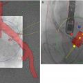
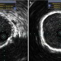
Fig. 34.1
(a) Balloon valvuloplasty of the native aortic valve. The balloon filled with diluted radiocontrast is seen extending from the left ventricular outflow tract to the aortic root. The posterior wall of the flat aortic sinus tents to a point (arrow) as calcium is displaced by balloon inflation. AMVL anterior mitral valve leaflet, Ao aorta. (b) Following deployment of the aortic prosthesis, the displaced calcium (arrow) is seen tenting the posterior aortic sinus. The shaft of the partially collapsed balloon (blue arrowhead) and guidewire are seen
Prosthesis Positioning
Prosthesis positioning and deployment can be straightforward when there are clear angiographic and echocardiographic landmarks, the device is coaxial with the long axis of the left ventricular outflow tract and aortic root, and the echocardiographer and interventional cardiologist agree on the position. It can also be extremely difficult when some of these factors are not present and particularly when either the angiographic or echocardiographic images suggest the position is appropriate and the other modality suggests the position is not correct. A superior TAVR team understands that discrepancies will occur, that when discrepancies occur the “right” answer is the one that results in the best outcome for the patient , and that being “wrong” is an opportunity to discover pitfalls in the current state of knowledge and an opportunity to advance the field and the imaging discipline.
Following balloon valvuloplasty, the prosthesis is then positioned in the ascending aorta prior to crossing the aortic valve. A combined echocardiographic and fluoroscopic approach to prosthesis positioning minimizes risk of a valve being deployed either too aortic or too ventricular. Poor position at deployment results in risk of the prosthesis embolizing, significant paravalvular aortic regurgitation, or malfunction due to suboptimal leaflet capture and interference with the prosthesis [10]. Positioning the prosthesis optimally for deployment requires relatively rapid decision making, as the prosthesis obstructs the critically stenosed aortic valve frequently compromising cardiac output with resultant hypotension.
Fluoroscopic guidance of TAVR aims to place the prosthesis with approximately one-third of the prosthesis ventricular to the base of the aortic cusps [11]. With echocardiographic guidance we aim to have the ventricular end of the prosthesis contact the intervalvular fibrosa just aortic to the hinge point of the anterior mitral leaflet, that is, the junction of the intervalvular fibrosa with the moving portion of the anterior mitral leaflet [9, 10]. Since the intervalvular fibrosa can range from quite lengthy to almost nonexistent, this can result in a long or very short landing zone. Appropriate placement in a short landing zone is demanding, and malplacement is more common with short as compared with normal or lengthy landing zones. If the prosthesis is placed too ventricular (“low”), the valve may embolize, interfere with the mitral valve, allow marked regurgitation, or be associated with persistent aortic stenosis if the aortic end of the prosthesis fails to capture the native aortic leaflets and keeps them out of the transvalvular flow path. Figure 34.2 demonstrates both the prosthesis contacting the moving portion of the anterior mitral leaflet and the native aortic leaflets overhanging the prosthesis with resultant residual aortic stenosis. A second prosthesis deployed more aortic (“higher”) will correct the residual aortic stenosis but cannot correct the interference with the mitral valve.
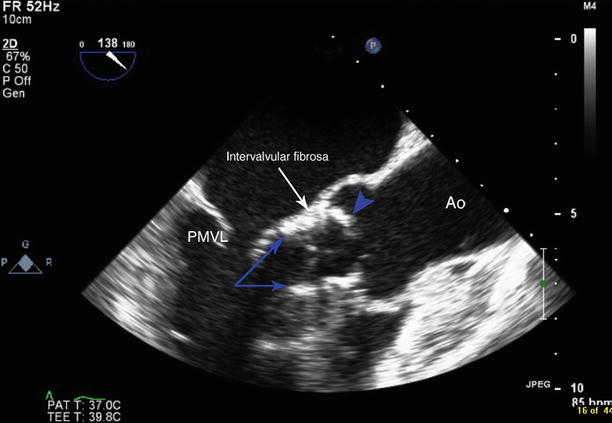
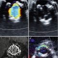
Fig. 34.2
The transcatheter aortic valve is deployed too low. The ventricular ends of the valve stent posts are seen within the left ventricular outflow tract (blue arrows) contacting the mobile portion of the anterior mitral leaflet. The aortic end of the valve is seen just aortic to the level of the intervalvular fibrosa (white arrow). Native aortic leaflet is seen overhanging the aortic end of the transcatheter aortic valve (blue arrowhead). PMVL posterior mitral valve leaflet, Ao aorta
Despite the complications of placing the prosthesis too ventricular (“low”), many operators prefer to err in that direction to avoid placing the prosthesis too aortic (“high”) since the consequences of an excessively aortic placement include severe aortic regurgitation, a high likelihood of embolization, left coronary obstruction, and damage to the sinotubular ridge if the sinuses of Valsalva are short. Left coronary obstruction can be identified by direct anatomic visualization, high velocity Doppler flow in the left coronary or by ventricular dysfunction commencing shortly after deployment. Figure 34.3 demonstrates deployment of a prosthesis that is too aortic. As is commonly the case, the prosthesis embolized shortly after deployment.
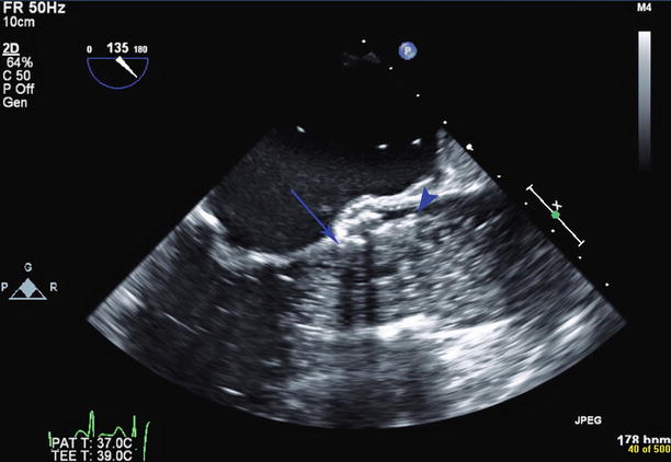
Fig. 34.3
Still frame of aortic valve deployment. A balloon filled with dilute radiopaque contrast is seen within the aortic root and left ventricular outflow tract. The ventricular end of the valve stent is too high, at the level of the native aortic valve annulus (blue arrow). The aortic end of the valve stent (blue arrowhead) is seen above the sinotubular junction. The valve subsequently embolized
Paravalvular Aortic Regurgitation
Immediately following deployment once the valve is seen to be stable, color Doppler is used to assess for paravalvular regurgitation (Fig. 34.4). At this stage, the guidewire is usually still across the aortic prosthesis, and differentiation between transvalvular and paravalvular aortic regurgitation may be difficult. Assessment of regurgitation is performed in both the short- and long-axis views. Some degree of paravalvular aortic regurgitation is reported in 80–96 % of cases [1]. In most cases, the degree of regurgitation is trivial or mild. Moderate and severe paravalvular regurgitation have been shown to be an independent predictor of short- and long-term mortality [1, 7, 12]. In the case of greater than mild paravalvular regurgitation, the prosthesis may require further balloon dilatation, or implantation of a second, overlapping transcatheter valve [1]. In the case of self-expanding valves, repositioning may improve the regurgitation. Once the guidewire has been withdrawn, a further assessment for any transvalvular regurgitation should be made (Fig. 34.5). Although rare, leaflet dysfunction can occur and requires further intervention [1, 13, 14].
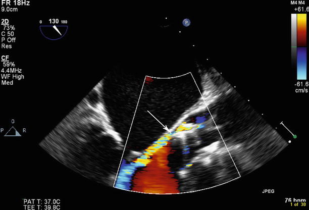
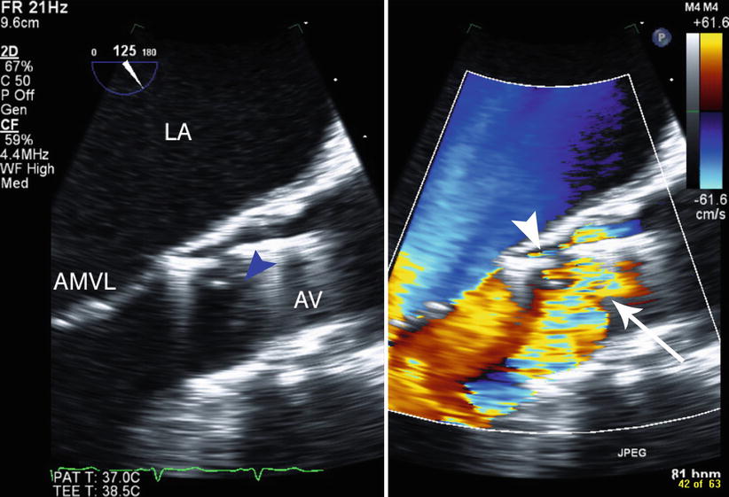
Fig. 34.4
Post-deployment of transcatheter aortic valve, paravalvular aortic regurgitation is seen posteriorly in the area of the noncoronary cusp (arrow)
Fig. 34.5
Following deployment of the prosthesis, there are both paravalvular regurgitation (arrowhead) and leaflet dysfunction causing transvalvular regurgitation. The two-dimensional image (left panel) shows malcoaptation of the prosthesis leaflets (blue arrowhead), LA left atrium, AMVL anterior mitral valve leaflet, AV transcatheter aortic valve prosthesis
Assessment of paravalvular regurgitation can prove difficult as there is commonly more than one site of regurgitation and the regurgitant jets are frequently eccentric. Furthermore, the grading system for aortic regurgitation was developed for valvular, not paravalvular jets. In the PARTNER trial echo sub-study, paravalvular aortic regurgitation was graded according to the Valve Academic Research Consortium Criteria (Table 34.1) [6], which adds the circumferential extent of the regurgitation in the short-axis view to traditional assessment criteria. Paravalvular aortic regurgitation that extends less than 10 % of the perimeter is graded mild, 10–20 % is graded moderate, and greater than 20 % is graded severe. Care must be taken to assess the circumferential extent of the regurgitation at the level of the vena contracta, as assessment made toward the left ventricular outflow tract will image the jet of the regurgitation and will overestimate the degree of regurgitation. As in valvular aortic regurgitation, the proportion of the jet width occupying the left ventricular outflow tract (LVOT) suggests mild regurgitation where less than 25 % of the LVOT is occupied and severe regurgitation where greater than 65 % of the LVOT is filled with regurgitant jet. A dense jet on continuous wave Doppler supports moderate or severe regurgitation, and a pressure half time of less than 200 ms is consistent with severe regurgitation. A greatly increased left ventricular outflow tract flow on pulse wave Doppler relative to the pulmonary outflow tract may also support more severe regurgitation. Similarly, holodiastolic flow reversal seen in the descending aorta strongly suggests that the aortic regurgitation is severe. At our institution, we classify trivial jets as those that are extremely narrow, limited to the distal left ventricular outflow tract and judged to be hemodynamically insignificant. Classification into mild, moderate, or severe is then based on the above criteria. The difficulties in accurately determining aortic regurgitation severity have led many investigators to pursue novel techniques of assessment. Some, such as use of three-dimensional color imaging, are promising but not yet commonly used routinely [15]. Sinning has proposed a simple hemodynamic assessment of aortic regurgitation severity called the aortic regurgitation index which can be very useful to resolve ambiguous cases [16].
Table 34.1
Prosthetic aortic valve regurgitation criteria (central and paravalvular)
Parameter | Mild | Moderate | Severe |
|---|---|---|---|
Valve structure and motion | |||
Mechanical or bioprosthetic | Usually normal | Usually abnormal | Usually abnormal |
Structural parameters | |||
Left ventricular size | Normal | Normal/mildly dilated | Dilated |
Doppler parameters (qualitative or semiquantitative) | |||
Jet width in central jets (% LVO diameter): colora | Narrow (≤25 %) | Intermediate (26–64 %) | Large (≥65 %) |
Jet density: CW Doppler | Incomplete or faint | Dense | Dense |
Jet deceleration rate (PHT, ms): CW Dopplerb | Slow (>500) | Variable (200–500) | Steep (<200) |
LV outflow vs. pulmonary flow: PW Doppler | Slightly increased | Intermediate | Greatly increased |
Diastolic flow reversal in the descending aorta | |||
PW Doppler | Absent or brief early diastolic | Intermediate | Prominent, holodiastolic |
Cicumferential extent of paraprosthetic AR (%)c | <10 | 10–20 | >20 |
Doppler parameters (quantitative) | |||
Regurgitant volume (ml/beat) | <30 | 30–59 | >60 |
Regurgitant fraction (%) | <30 | 30–50 | >50 |
Paravalvular regurgitation can be multifactorial with selection of an undersized valve, and deployment either too aortic or too ventricular being the most common [17]. Calculation of a cover index, defined as 100 × (prosthesis diameter – transesophageal echocardiography annulus diameter)/prosthesis diameter, has also been found to be a predictor of paravalvular aortic regurgitation with a suggestion in the original publication that paravalvular AR did not occur when the cover index was greater than 8 % [18]. However, paravalvular AR has been reported with a cover index greater than 8 % [16] and a greater reliance on three-dimensional imaging to provide an annular area is being used [7]. The use of aortic annular area as measured on multidetector computed tomography has been shown to be predictive of moderate or severe aortic regurgitation. Recent research has shown that by slight oversizing of the prosthesis size using the mean annular area by 5 to 10 %, this may reduce the incidence of significant regurgitation due to an undersized valve [7, 19]. Marked asymmetric calcium distribution has also been associated with regurgitation [17]. Transvalvular regurgitation can result from post-deployment balloon dilatation with increased balloon volume, and there was a suggestion of increased strokes with post-dilatation in one series [12, 20, 21].
Related posts:
 Transcatheter Aortic Valve Replacement: Current Evidence from Large Multicenter Registries
 Positron Emission Tomography Evaluation of Aortic Stenosis
 Pathologic Findings in Aortic Stenosis
 Transcatheter Aortic Valve Replacement in Patients with Chronic Kidney Disease: Pre-procedural Assessment and Procedural Techniques to Minimize Risk for Acute Kidney Injury
 Aortoiliofemoral Angiography and IVUS
 Valve-in-Valve for Transcatheter Aortic Valve Replacement: Do Imaging Requirements Change?
Stay updated, free articles. Join our Telegram channel

Full access? Get Clinical Tree


