Abstract
Cardiac computed tomography has seen a rapid technical development over the past two decades, and currently allows reliable, noninvasive coronary angiography on a routine basis. Associated exposure to radiation has gradually decreased with contemporary CT technology. Novel functional applications, such as stress myocardial perfusion imaging and CT derived fractional flow reserve calculation, expand the applicability of cardiac CT from a technique to rule out coronary artery disease, to a means to risk stratify patients and make therapeutics decisions.
Keywords
Computed tomography, Coronary angiography, Coronary artery disease, Myocardial perfusion, Myocardial infarction
5.1
Development of cardiac CT
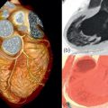
In 1972, the first CT scanner was designed by the engineer Geoffrey N. Hounsfield at an English company named EMI Ltd. Together with Allan C. Cormack, a physicist from Cape Town who developed the mathematical foundation for the reconstruction of cross-sectional images from transmission measurements, Hounsfield was honored with the Nobel Prize for Physiology or Medicine in 1979. The first CT scanners, at this time known as a computerized axial tomography (CAT) scanner, were limited to cranial imaging, until whole-body scanners were released in 1975. The rotation speed of these first mechanical CT scanners was insufficient to image moving organs. Therefore, in the late 1970s, a very fast CT system without rotating parts was developed, dedicated to imaging the heart. The electron-beam CT scanner (cine CT; ultrafast CT) has a static anode and detector rings on opposite sides of the gantry. By electromagnetically directing an electron beam along the tungsten anode ring, images can be acquired in a very short time (50 ms or less). EBCT has been used for different cardiovascular applications, including calcium imaging, CT coronary angiography, and myocardial perfusion imaging. Because of high operating costs and technical obstacles for further (multislice) development, the EBCT technology has largely disappeared from clinical use. Introduced in the early 1990s spiral CT permitted fast coverage of large body sections, which was particularly useful for angiographic CT applications. Spiral CT requires continuous tube-detector rotation, which could only be accomplished by removing the physical connections (wires) between the stationary and rotating scanner elements. As for all CT scanners today, the cables have been replaced by slip-ring and wireless technology that allows for energy and data exchange via nonfixed connections. Since the end of the 1990s, CT scanners have been equipped with an ever-increasing number of detector rows. The combination of spiral imaging, faster rotation speeds, more efficient reconstruction algorithms (half-scan algorithms), and multiple detectors allowed for detailed imaging of the moving heart and coronary arteries in the early 2000s ( Figure 5.1 ).

5.2
Technical principles and contemporary technology
5.2.1
Computed tomography
5.2.1.1
Roentgen generation
The goal of computed tomography is to differentiate tissues and structures within the human body in a cross-sectional manner. What CT measures is the degree by which material affects roentgen radiation as it passes through. Conventional X-ray images are projection images that display the cumulative roentgen attenuation of an entire object. Computed tomography is a technique that acquires a large number of projection images from different rotational angles and uses the cumulative attenuation profiles to calculate the spatial distribution of the roentgen attenuation throughout the interrogated cross-sectional plane. In cardiac imaging, where temporal resolution is essential, projections acquired during half of a full system rotation are sufficient for image reconstruction.
The core components of a CT system are the X-ray tube and the roentgen detectors, which are positioned at opposing sides of the scanner gantry. The high-power roentgen generator produces X-rays with a variable energy level; the maximum kV level is selectable, generally between 70 and 150 kV. The tube potential (kV) relates to the energy level of the photons, where X-ray with a higher kV are more penetrating than the weaker low kV photons. The X-ray beam is not a monochromatic source at a single kV level, but will include a spectrum of energy levels. The lowest energy levels, which do not contribute to the image generation, are filtered out before they enter the gantry. The number of photons per time unit (flux) is expressed in milli-Ampere. The point where electrons from the cathode collide with the anode to generate roentgen photons is called the focal spot. A small focal spot improves spatial resolution, but creates more heat at a constant flux. The anode rotates to better disperse the heat. Repetitive alternation of the focal spot (or more accurately focal ring) by electromagnetically changing the direction of the electrons allows for double-image sampling. Acquisition of slightly overlapping images using the “flying focal spot” improves the image quality in the longitudinal direction. Collimators are used to shape the X-ray beam to fit the detectors on the opposite side of the gantry.
5.2.1.2
Roentgen detection
The purpose of the detectors on the opposite side is to detect and quantify photons, augment the signal, and convert it to digital form. The requirements for the detectors are high. They need to be small, with minimal dead space separating them in the interest of spatial resolution; the reaction to exposure needs to be fast and proportional; and after exposure the detectors need to return to standby immediately to receive the following exposure. Sensitivity needs to be high, and (electronic) noise as low as possible. In order to accommodate faster scanning and multidetector row configuration, detectors with xenon ionization chambers have been replaced by solid-state scintillating ceramic detectors, which have shorter decay times. The ceramics convert the X-ray photons into light, which is then detected and converted to a proportional electrical signal. These electric signals are then collected for further processing and image reconstruction ( Figure 5.2 ). New integrated and miniaturized electronics designs can reduce electronic noise.

Originally, CT scanners were equipped with a single row of detectors, exposed by a narrow fan-shaped X-ray beam. The number of parallel rows of detectors has increased dramatically over the past 15 years. Contemporary scanners have between 64 and 320 rows of detectors, each measuring 0.5–0.625 mm in width, as measured in the center of rotation. Per rotation, current scanners can cover a longitudinal distance between 38 and 160 mm. The number and width of the detector system is referred to as the detector collimation, for instance 128 × 0.625 mm = 80 mm.
5.2.1.3
Dual-source CT
Dual-source CT systems are equipped with a double tube-detector system. The two systems are mounted on the scanner by a rotational offset of 90–95°. The main purpose of the system is to improve temporal resolution, which is the time needed to acquire data for a single image. Instead of needing a half rotation to acquire the images, all required projections can be gathered using in a 90° rotation using the dual-source system. Additional applications are double-output imaging in very obese patients, ultra-fast z-axis coverage scan modes to avoid motion in uncooperative (pediatric) patients, and improved tissue differentiation by imaging at nonidentical tube voltages (dual-energy CT).
5.2.1.4
Scan modes
CT scanners can operate in different acquisition modes, which become evident from the movement of the table ( Figure 5.3 ). Of the available scan modes in use today, the axial mode has been in operation from the beginning. In this mode, one set of axial images is acquired while the table remains stationary. After each acquisition, the table moves to the next consecutive position. In cardiac CT, this is also referred to as the sequential, step-and-shoot, or prospective mode. After the physical connections (cables) between the rotating and stationary parts of the scanner had been removed, continuous rotation of the tube-detector system combined with uninterrupted table propagation became possible. This scan mode, referred to as spiral or helical scanning, allows much faster longitudinal coverage, which was essential to the development of CT angiography. Because projections are acquired at slightly incremental table positions, a form of longitudinal interpolation is necessary before axial images can be reconstructed. If the width of the detectors rows completely cover the organ of interest, such as is the case with 320-row imaging of the heart, no table movement is required anymore. If the same section is imaged repetitively, structural motion or dynamic contrast enhancement may be visualized. Serial imaging may be accomplished by repeating a complete volumetric scan, repeating acquisitions at the same table location, or a combination of the two (shuttle mode).

5.2.2
ECG-synchronized CT of the heart
The most important aspect of cardiac imaging, which separates it from most other applications, is the need for ECG synchronization. This includes two aspects. First, if all images cannot be acquired by a single acquisition during a single heart cycle, then each partition of the total scan needs to be acquired during the exact same phase of contraction over several heart cycles. Imaging with neglect of cardiac phases will cause blurring, nonalignment, or even loss of entire structures. Secondly, the temporal resolution of cardiac CT is limited. This means that the heart cannot be imaged well without blurring during phases of rapid displacement. The preferential phases to image the heart are during mid-diastole, just before atrial contraction, or at the end of systole. To create images during the same phase of relative cardiac immobility, either the data acquisition or the image reconstruction needs to be synchronized to the rhythm of the heart. Several cardiac scan modes, with modifications, can accomplish this: the ECG-gated conventional-pitch spiral mode, the ECG-triggered axial mode, the ECG-triggered stationary mode, and the ECG-triggered high-pitch spiral mode.
5.2.2.1
ECG-gated spiral CT
While not the earliest cardiac scan mode, it was the ECG-gated spiral CT that propelled the development of noninvasive CT coronary angiography. The principle of the ECG-gated spiral mode is the acquisition of a continuous, spatially overlapping spiral CT scan, with a simultaneous recording of an ECG trace ( Table 5.1 ). Using the ECG trace, CT data acquired during the same phase of contraction is gathered to reconstruct a complete data set. The advantage of ECG-gated spiral CT is that the technique is very robust and flexible. Images can be reconstructed during any cardiac phase, allowing selection of the optimal dataset with the fewest motion artifacts. The moment of reconstruction (reconstruction window) can be placed anywhere within the heart cycle. It can be positioned at an absolute time interval after the previous R-wave or before the next R-wave. Alternatively, it can be placed at a relative position, for instance at 70% of the R-to-R interval. After the scan has been performed, the ECG synchronization may be manually corrected, for each individual beat, if necessary. Spiral CT acquisition allows for overlapping image reconstruction at smaller increments to improve perceived longitudinal image quality. The major drawback of ECG-gated spiral CT is the high radiation exposure caused by oversampling. The pitch is a term used in spiral CT to quantify the scan speed and is defined as the distance the table moves per tube-detector rotation. For nongated spiral CT scans, the table could advance by as much as twice the detector collimation width per rotation. In that case, the pitch is 2 (without unit). This is different for cardiac CT. To be able to reconstruct every cardiac phase, each table position needs to be sampled during an entire heart cycle. To anticipate changes in heart rate, the exposure per table position is generally more than a single heart cycle. Depending on the heart rate, the pitch varies from 0.15 to 0.5 for ECG-gated spiral CT. The amount of radiation used per longitudinal distance is relatively high for the conventional ECG-gated spiral CT. One can calculate that when the temporal resolution of a 4-slice scanner is 250 ms (at a rotations time of 500 ms), and each position is scanned for 1.5 heart cycles at a heart of 60/min, then the ratio of minimal needed exposure is 1/6th of the actual exposure. Modifications of the ECG-gated spiral mode have been designed to reduce the overall exposure. Using the prospective ECG-triggered tube current modulation, it is possible to reduce the tube output to 4–20% of the nominal output during the phases that are less likely to be needed for evaluation. The ECG-triggered tube output modulation, also known as ECG pulsing, can significantly reduce the overall exposure. While these algorithms are more vulnerable to arrhythmia than conventional ECG-gated spiral algorithms, advantages in terms of ECG editing are still retained. However, in patients with a stable heart rate, axial scan protocols have largely replaced spiral protocols as the default scan mode.
| ECG-gated spiral CT | ECG-triggered axial CT | |
|---|---|---|
| Synonyms | Helical mode Spiral mode | Prospective mode Sequential mode Step-and-shoot mode |
| ECG synchronization | Retrospectively, from recorded ECG trace | Prospectively, from online ECG signal |
| Table motion | Continuous | Interrupted |
| Exposure | Continuous | Interrupted |
| Scan duration | Predictable, based on selected table speed (based on expected heart rate) | Less predictable, depending on actual heart rate and rhythm regularity |
| Modifications | Prospectively ECG-triggered tube current modulation ( pulsing ) to reduce tube output during low-priority phases | Prolonged exposure to increase available cardiac phases ( padding ) |
| Advantages | Robust, arrhythmia resistant | Lower radiation exposure |
5.2.2.2
ECG-triggered axial CT
The axial scan mode implies that images are acquired with a stationary table position. Timing of the scan within the heart cycle is planned in advance, and the online ECG trace is used to trigger the image acquisition. Based on the previous heart cycles, the scanner estimates when the desired cardiac phase will take place. After the acquisition of a single set of images, the table will move to the next consecutive position and wait for a trigger. The advantage of the axial mode (also known as sequential, prospectively triggered, or step-and-shoot mode) is that exposure only occurs during the phase that is intended for reconstruction, thereby minimizing the overall radiation dose. The drawback of a prospectively triggered acquisition is that it relies on the regularity of the heart rhythm and that no alternative cardiac phases can be reconstructed in case of suboptimal image quality. Because advancement of the table takes time, acquisition generally occurs every second heartbeat, or every third heartbeat in case of a fast heart rate. Using earlier generations multislice CT with slower rotation speeds, this acquisition mode was considered unacceptably vulnerable to arrhythmia. Then, interpretation often required comparison of datasets reconstructed during different phases of contraction. Contemporary faster scanners, aided by betablockers, have made image quality more reliable. In addition, the ECG-triggering algorithms have become smarter. In case of a premature beat, the acquisition at a given location can be stopped and repeated once regularity is restored. In addition, the duration of exposure at each location can be extended beyond the minimum required for a single-phase reconstruction, sometimes called “padding”, to allow for reconstruction of several cardiac phases while still avoiding exposure during other phases.
5.2.2.3
ECG-triggered stationary mode
If the number of detector rows allows for complete coverage of the organ of interest, then no table movement is necessary. Some of the recently released scanners have a detector collimation of 16 cm, which covers the entire heart. Without the need for table movement, images can be acquired in a single heart cycle, or exposure at the same location can be extended to several heart cycles to improve temporal resolution (discussed elsewhere), using ECG-triggering to image the desired cardiac phase.
5.2.2.4
ECG-triggered high-pitch mode
Second- and third-generation dual-source CT scanners have the option of an ECG-triggered high-pitch spiral scan protocol. Operating at a high table speed, the entire heart can be covered during a single cardiac cycle. Although the entire acquisition takes 150–250 ms, individual images are acquired with a temporal resolution of 66–75 ms. The advantage of the ECG-triggered high-pitch protocol (also referred to as Flash®) is that the entire heart is acquired during a single cycle, although there is a small phase shift from the first to the last image, at a very low exposure. The drawback is that only a single cardiac phase is available, and that the prolonged exposure within the heart cycle requires a low and regular heart rate.
5.2.3
Image reconstruction
While the concepts of computed tomography were developed a long time ago, the rate of development was largely driven by progress in computer technology. The quantity of information created by a CT scanner is immense, and reconstruction of images out of the attenuation profiles requires substantial processing power. The objective of image reconstruction is to display the distribution of a specific tissue characteristic throughout a cross-section or volume. In case of CT, this property is the tissue-specific roentgen attenuation coefficient ( μ ). To calculate this, we have at our disposal a large number of attenuation profiles obtained from a series of rotational angles, which are summations of the attenuation of X-ray through an object consisting of tissues with varying attenuation coefficients. The challenge of CT imaging is to estimate the attenuation distribution based on these samples. From the calculated, spatially distributed attenuation values, a so-called CT number is calculated. The CT number, expressed in Hounsfield units (HU), represents the relative attenuation compared to water and is calculated as:
CT Number HU : μ tissue − μ water / μ water * 1000
Related posts:
Stay updated, free articles. Join our Telegram channel

Full access? Get Clinical Tree


