Critical Procedures for Acute Resuscitations
Michael Y. Woo
Ashraf Fayad
INTRODUCTION
The resuscitation of acute illness often involves simultaneous diagnostic efforts (gathering data, forming hypotheses) and active interventions to treat the acutely ill patient. Most of the preceding chapters in this section devoted to acute injury and illness have focused on diagnosis. This chapter focuses on ultrasound assistance for emergent bedside procedures in the most critical moments of emergency medicine practice.
ADULT CENTRAL VENOUS ACCESS
Clinical Indications
In the Emergency Department (ED), central venous catheter (CVC) insertion is not uncommon and is often a lifesaving procedure. Once established, CVCs can be used for fluid resuscitation, administration of medications, and monitoring of central venous pressures. Occasionally, the CVC can simply serve as an alternative venous access when peripheral venous access is limited, or can facilitate the placement of a transvenous pacemaker wire. Blind central venous punctures guided only by external landmarks are associated with significant morbidity and rarely mortality. Failure rates for placement of CVCs have been reported to be 10% to 19% (1,2). Mechanical complication rates are reported to occur in 5% to 19% of patients (1, 2, 3, 4, 5). These complications are dependent upon the site chosen for insertion, nature of underlying disease (emphysema, bleeding dyscrasia, mechanical ventilation), patient anatomy, prior CVC insertion, and physician experience (1, 2, 3,6). The most common complications
include arterial puncture, hematoma, and pneumothorax (1). Other reported complications include catheter malposition, adjacent nerve injury, artery or vein wall laceration, cardiac arrhythmias, hemothorax, chylothorax, pericardial tamponade, hemomediastinum, pneumomediastinum, air embolism, guidewire embolism, and death (6, 7, 8, 9, 10, 11, 12).
include arterial puncture, hematoma, and pneumothorax (1). Other reported complications include catheter malposition, adjacent nerve injury, artery or vein wall laceration, cardiac arrhythmias, hemothorax, chylothorax, pericardial tamponade, hemomediastinum, pneumomediastinum, air embolism, guidewire embolism, and death (6, 7, 8, 9, 10, 11, 12).
Traditionally, CVCs have been inserted using “blind techniques” that rely on anatomical landmarks and their relationship to the underlying target vessel. Real-time two-dimensional ultrasound machines have been used to aid CVC insertion. Advantages of ultrasound include exact localization of the target vein, visualization of the relationship of the target vein to the adjacent artery (13,14), detection of anatomic variations (15, 16, 17), avoidance of veins with preexisting thrombosis, and real-time guidance of the needle into the target vein. There have been numerous prospective, randomized, controlled trials revealing that real-time ultrasound guidance is superior to traditional landmark techniques (18, 19, 20, 21, 22, 23, 24, 25, 26, 27). This literature has been critically evaluated with several meta-analyses (28, 29, 30, 31, 32). Real-time ultrasound guidance improves catheter insertion success rates, reduces the number of venipuncture attempts prior to successful placement, and reduces the number of complications associated with catheter insertion (30,31). The strength of evidence has prompted the Agency for Healthcare Research and Quality (AHRQ) to publish a report stating that ultrasound-guided insertion of CVCs is a top 10 patient safety practice to prevent hospital iatrogenesis and is specifically among the practices “… most highly rated in terms of strength of evidence supporting more widespread implementation” (32). The National Institute of Clinical Excellence performed a technology appraisal for the United Kingdom’s National Health Service that stated, “…the use of 2-D imaging ultrasound guidance should be considered in most clinical circumstances where CVC insertion is necessary either electively or in an emergency situation” (33).
Image Acquisition
A 7.5- to 10-MHz linear array transducer is typically used for real-time ultrasound-guided CVC insertion. Other necessary components include a sterile ultrasound transducer sleeve, gel, and rubber bands (Fig. 8.1). Ultrasound images of central vessels may be obtained in short or long axis using either a static or a dynamic approach (Figs. 8.2, 8.3, 8.4 and 8.5). Ultrasound-guided needle insertion has been described using both approaches. In general, visualizing and subsequently accessing the target vessel in short axis has been
shown in one study to be easier to learn for novice users, but either approach may be employed, depending on the site of access and the experience of the person performing the procedure (34).
shown in one study to be easier to learn for novice users, but either approach may be employed, depending on the site of access and the experience of the person performing the procedure (34).
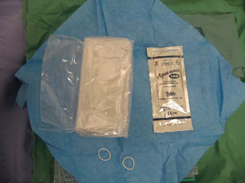 FIGURE 8.1. Sterile Ultrasound Transducer Packet Includes a Nonlatex Sleeve, Rubber Bands, and Gel. |
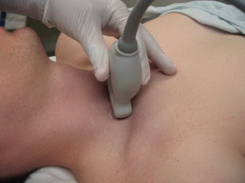 FIGURE 8.2. Photo of Transducer in Transverse Orientation for Imaging the Right Internal Jugular Vein. |
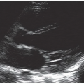
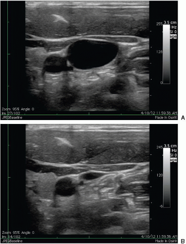 FIGURE 8.3. Ultrasound of internal jugular vein noncompressed (A) and compressed (B). |
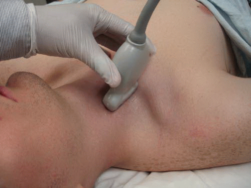 FIGURE 8.4. Photo of Longitudinal Orientation of Transducer for Imaging Right Internal Jugular Vein. |
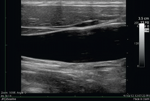 FIGURE 8.5. Corresponding Ultrasound of the Long-Axis View of the Internal Jugular Vein. |
General principles: static ultrasound (landmarking)
This technique involves ultrasound visualization of landmarks in relation to internal structures. The area of interest is first centered on the screen and anatomical structures are identified. Indelible ink is then used to mark the patient’s skin at either end of the transducer. The transducer is then turned 90 degrees while keeping the area of interest in the center of the screen. Indelible ink is again used to mark the skin at either end of the transducer. Lines are then drawn to connect the dots and the ‘X’ mark is used to identify needle entry points (Fig. 8.6). It is important to ensure that the transducer is placed perpendicular to the skin to mimic the direction and angle of the needle. This will give an accurate depiction of the depth of the target and therefore the distance for the needle advancement. This method is appropriate for larger targets and when the risk of needle injury to other structures is low. The static ultrasound technique is more efficient and safer when compared to the blind landmarking method (35).
Dynamic ultrasound (real-time)
Dynamic ultrasound is the real-time visualization of the needle while hitting the target. This method can be more technically challenging, especially while maintaining continuous needle visualization. However, it is the ideal method for accessing smaller targets and when there is risk of needle injury to the surrounding structures. Limitations of this technique depend on the ability to correctly position the probe and visualize the needle in certain anatomic areas. Needle visualization can be facilitated through the in-plane (longaxis) or out-of-plane (short-axis) approach.
In-plane (long-axis) technique
The in-plane or long-axis technique involves inserting the needle off the end and along the long axis of the transducer (Fig. 8.7;  VIDEO 8.1). Both the target and the needle are visualized at the same time without having to move the transducer during the procedure. This technique allows the operator to visualize the needle from the skin to the target area of interest. Visualization of the vertical depth of the needle tip during insertion is optimal using this approach versus the out-of-plane or short-axis technique. Visualization of the needle is dependent on the angle of the needle relative to the skin. The shallower the angle, the easier it is to visualize the needle (Fig. 8.8). Many of the newer ultrasound machines have now incorporated needle visualization software and hardware to make visualization less dependent on the angle of the needle.
VIDEO 8.1). Both the target and the needle are visualized at the same time without having to move the transducer during the procedure. This technique allows the operator to visualize the needle from the skin to the target area of interest. Visualization of the vertical depth of the needle tip during insertion is optimal using this approach versus the out-of-plane or short-axis technique. Visualization of the needle is dependent on the angle of the needle relative to the skin. The shallower the angle, the easier it is to visualize the needle (Fig. 8.8). Many of the newer ultrasound machines have now incorporated needle visualization software and hardware to make visualization less dependent on the angle of the needle.Needle insertion is usually at a more shallow angle (15 to 30 degrees) compared with the out-of-plane technique (45 to 60 degrees). As a result, the needle will need to travel further to reach the target. The operator should ensure that the needle is of sufficient length to reach the target prior to commencing the procedure.
Out-of-plane (short-axis) technique
The out-of-plane or short-axis technique involves inserting the needle at the middle of the transducer that is centered over the target. The needle is inserted at a steep angle of 45 to 60 degrees. The distance the needle must be inserted is a closer approximation to what is visualized on the screen as a result of the steeper angle of insertion (Fig. 8.9A). Care must be taken to first visualize the needle tip anterior to the target. The needle tip appears as an echogenic point (Fig. 8.9B). Once the tip is visualized, it is important to advance the needle while moving the transducer distally in order to continually visualize the needle tip. If the transducer is not moved to keep up with the needle tip, a ring-down artifact will often be visualized, but this corresponds to the needle shaft rather than the needle tip (Fig. 8.9C).
General approach
Once the approach is planned, position the patient in the usual fashion according to the desired anatomic approach. Position the ultrasound screen directly in front of the operator while performing the procedure. The screen should be in the same line of sight as the direction that the needle is inserted. The transducer should be oriented correctly so that the screen side is the same as the operator side. For example, if the left side of the footprint of the transducer is depressed by a finger, this should correspond to the left side of the screen and therefore applied to the skin of the patient so that this is on the left side of the operator (Fig. 8.10).
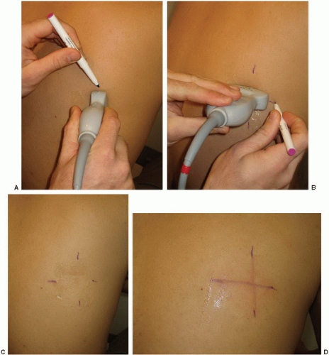 FIGURE 8.6. Landmarking. The transducer is placed perpendicular to the skin with the area of interest centered on the screen, and the skin is marked on either side of the transducer with indelible ink (A). The transducer is rotated 90 degrees and the skin marking is repeated (B, C). The marks on the skin are then connected. The center of the “X” indicates the point of insertion (D). |
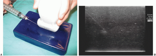 FIGURE 8.7. Model Demonstrates an In-Plane (Long-Axis) Technique. The needle is inserted at the end of the transducer and advanced by maintaining its position directly under the transducer (A). The needle shaft and tip appear on the screen (B). |
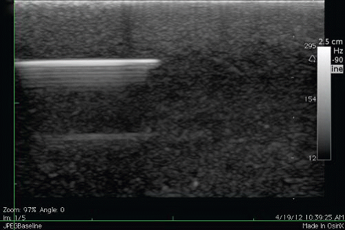 FIGURE 8.8. Ultrasound Showing Advancement of a Needle at a Shallow Angle. The shaft and needle tip are highly echogenic when the angle of the needle to the skin is shallow. |
Perform a brief nonsterile ultrasound scan of the CVC insertion site. Regardless of anatomic approach, there is typically a pair of nonechogenic blood vessels running side by side (Fig. 8.3A). Adjust the gain and the depth so that the vessels are in the center of the screen. The artery is usually rounder, smaller in diameter, and more prominently pulsatile. The central vein is larger, more irregular in shape, and has a subtle undulating pulsatile quality. Localize the vein definitively by applying gentle pressure with the ultrasound transducer. The vein should compress easily and completely, while the artery will stay patent (Fig. 8.3B).
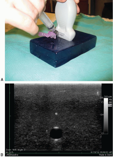 FIGURE 8.9. Model Demonstrates the Orientation of an Out-of-Plane (Short-Axis) Technique. The needle is inserted at the middle of the transducer that overlies the target (A). The needle tip appears as an echogenic dot using this approach (B). Ring-down artifact indicates the needle shaft (C). |
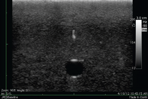 FIGURE 8.9. (Continued) |
Prepare the ultrasound transducer for sterile use as shown in Figures 8.11, 8.12 and 8.13. Apply a copious amount of ultrasound gel (sterile or nonsterile) directly to the transducer footprint. Slip the sterile sleeve over the transducer. Smooth all air bubbles away from the scanning surface to prevent imaging artifact. Secure the sleeve with rubber bands. Sterile gel on the skin will then be required to image the vessels. Although some physicians have advocated for using a sterile glove to insert central lines, it is important to note that this method of making the probe sterile does not meet recommended maximum sterile barrier precautions for the prevention of catheter-related blood stream infections (36).
Anatomy and Landmarks
Internal jugular vein approach
Place the patient in the Trendelenburg position with head turned contralaterally 30 degrees. Place the ultrasound transducer just superior to the clavicle between the two heads of the sternocleidomastoid muscle (Fig. 8.14). The right internal jugular vein anatomy and corresponding normal ultrasound findings are shown in Figures 8.15 and 8.16. For typical anatomy, the internal jugular vein is anterior and lateral to the carotid artery with the widest diameter just superior to the clavicle. Scan the length of the vein from the clavicle to the thyroid cartilage, taking into account the widest diameter, relationship to the carotid artery, and any variations of normal anatomy. Although the inplane technique is the preferred dynamic method due to its superior visualization of the needle throughout the procedure, the out-of-plane technique is often used in this area due to the limited space and large footprint of the transducer.
Subclavian vein approach
The subclavian vein is more difficult to visualize due to the presence of the clavicle. The clavicle creates shadowing posteriorly and partially obscures the vessels and pleura. The subclavian vein, however, has the lowest incidence of
catheter-related bloodstream infections compared with the internal jugular and femoral veins, and therefore, depending on the clinical circumstances, should still be strongly considered as a site for CVC insertion (37,38). The subclavian vein can be accessed from either an infra- or supra-clavicular approach as described below.
catheter-related bloodstream infections compared with the internal jugular and femoral veins, and therefore, depending on the clinical circumstances, should still be strongly considered as a site for CVC insertion (37,38). The subclavian vein can be accessed from either an infra- or supra-clavicular approach as described below.
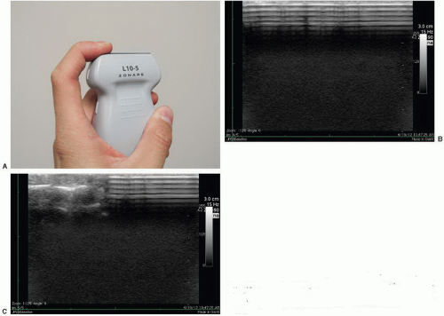 FIGURE 8.10. A finger depresses one side of the transducer (A). The ultrasound image without depressing one side of the transducer (B), contrasted with the image seen when the finger depresses the left side of the transducer (C). The transducer should be oriented so that the depressed side is on the left side of the operator. |
 FIGURE 8.11. Preparation of the Transducer. Begin by applying a copious amount of gel. |
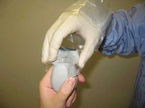 FIGURE 8.12. Use the Rolled Transducer Sleeve to Grab the Transducer to Maintain Sterility. |
Infraclavicular technique for subclavian vein
Place the patient in the Trendelenburg position with a small rolled towel between the shoulder blades. The patient’s arm is abducted 90 degrees to straighten the axillary vessels. The axillary vein travels from the axillary fold to the lateral border of the first rib, where it becomes the subclavian vein.
The subclavian vein runs obliquely and posterior to the clavicle, making ultrasound imaging of this vessel nearly impossible. The more distal axillary vein, on the other hand, is exposed for ultrasound examination. Place the ultrasound transducer just inferior to the most lateral aspect of the clavicle as in Figure 8.17. Right axillary vessel anatomy and corresponding ultrasound findings are depicted in Figures 8.18 and 8.19. With the transducer indicator directed toward the patient’s head, the axillary vein is typically anterior and inferior to the axillary artery. Note that transducer pressure may not collapse the vein completely due to its slightly deeper location beneath the skin. The axillary vein will completely collapse when the patient inhales against a closed glottis; this technique should be used to identify the vein and ensure absence of thrombus (Fig. 8.20; VIDEO 8.2). The vein and artery can also be distinguished from each other using color Doppler (Fig. 8.21;
  VIDEO 8.3). As the axillary vein travels medially, it runs adjacent to the pleura of the lung (Fig. 8.22). To avoid pneumothorax, care must be taken to place the transducer several centimeters lateral to the thoracic cage. Alternatively, approaching the cannulation of the axillary vein in-plane will allow for the tip of the needle to be identified through the entirety of its course, thereby avoiding puncturing the posterior vessel wall and entering the pleural space (39).
The subclavian vein runs obliquely and posterior to the clavicle, making ultrasound imaging of this vessel nearly impossible. The more distal axillary vein, on the other hand, is exposed for ultrasound examination. Place the ultrasound transducer just inferior to the most lateral aspect of the clavicle as in Figure 8.17. Right axillary vessel anatomy and corresponding ultrasound findings are depicted in Figures 8.18 and 8.19. With the transducer indicator directed toward the patient’s head, the axillary vein is typically anterior and inferior to the axillary artery. Note that transducer pressure may not collapse the vein completely due to its slightly deeper location beneath the skin. The axillary vein will completely collapse when the patient inhales against a closed glottis; this technique should be used to identify the vein and ensure absence of thrombus (Fig. 8.20;
VIDEO 8.2). The vein and artery can also be distinguished from each other using color Doppler (Fig. 8.21; VIDEO 8.3). As the axillary vein travels medially, it runs adjacent to the pleura of the lung (Fig. 8.22). To avoid pneumothorax, care must be taken to place the transducer several centimeters lateral to the thoracic cage. Alternatively, approaching the cannulation of the axillary vein in-plane will allow for the tip of the needle to be identified through the entirety of its course, thereby avoiding puncturing the posterior vessel wall and entering the pleural space (39).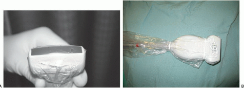 FIGURE 8.13. A: Smooth away any air bubbles that are seen in the gel. B: Secure the sleeve with rubber bands. |
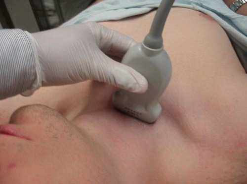 FIGURE 8.14. Transducer Orientation for the Transverse (Short-Axis) Approach to the Right Internal Jugular Vein. The transducer is placed just above the clavicle in between the two heads of the sternocleidomastoid. |
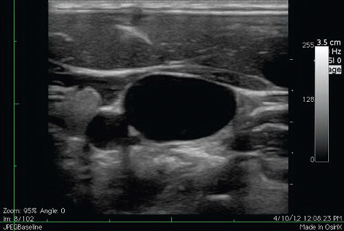 FIGURE 8.15. Corresponding Ultrasound Short-Axis View of the Right Internal Jugular Vein and Carotid Artery. |
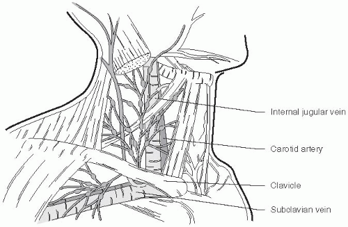 FIGURE 8.16. Anatomy of the Right Internal Jugular Vein and Carotid Artery. |
Supraclavicular technique for subclavian vein
The landmark technique was first described by Yoffa in 1965 using the insertion landmark of the sternocleidomastoid angle (40). The right side is usually chosen due to the lower pleural dome and absence of the thoracic duct. The linear array transducer is placed just superior and along the medial border of the clavicle (Fig. 8.23). In some circumstances, the supraclavicular area is challenging when using larger footprint linear array transducers given anatomical space limitations. An endocavitary transducer may be used instead with its much smaller footprint (Fig. 8.24). The transducer is first applied to the neck in a nonsterile fashion to visualize the internal jugular vein and the carotid artery. The transducer is then slid distally until the confluence of the internal jugular and
subclavian veins is encountered (Fig. 8.25; VIDEO 8.4). This area is further scanned to identify the subclavian artery and the pleura. The transducer can then be rotated to obtain a longitudinal view of the subclavian vein. Although technically more challenging, dynamic guidance using the inplane technique should be used. If necessary, static guidance using ultrasound land-marking for the depth and angle in which the cannulating needle needs to be advanced can be performed (41).
subclavian veins is encountered (Fig. 8.25;
VIDEO 8.4). This area is further scanned to identify the subclavian artery and the pleura. The transducer can then be rotated to obtain a longitudinal view of the subclavian vein. Although technically more challenging, dynamic guidance using the inplane technique should be used. If necessary, static guidance using ultrasound land-marking for the depth and angle in which the cannulating needle needs to be advanced can be performed (41).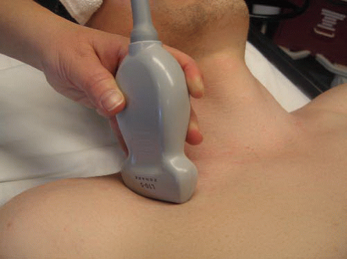 FIGURE 8.17. Transducer Placement for an Infraclavicular Approach to the Subclavian Vein. The transducer is placed inferior to the most lateral aspect of the clavicle. |
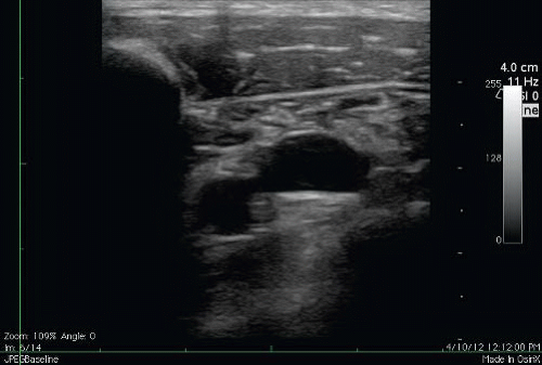 FIGURE 8.18. Corresponding Short-Axis View of the Axillary Vein and Artery. Note the shadow generated by the clavicle as well as the increased depth of the vein and artery. |
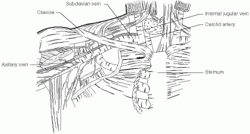 FIGURE 8.19. Corresponding Anatomy of the Axillary and Subclavian Vessels. |
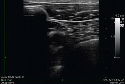 FIGURE 8.20. Complete Collapse of the Axillary Vein. This is achieved by asking the patient to place a thumb in his/her mouth. Request the patient to breathe in through the imaginary straw. The negative inspiratory force achieved by inhaling against a closed glottis collapses the axillary vein. |
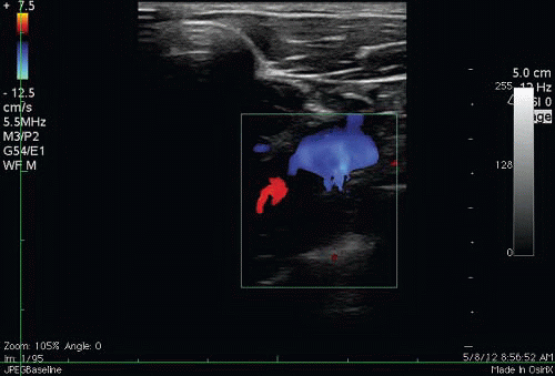 FIGURE 8.21. With the Addition of Color Doppler, the Axillary Artery (red) and Vein (blue) can be Further Distinguished from Each Other. The lower flow of the vein is identified and flowing in the opposite direction of the artery. |
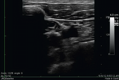 FIGURE 8.22. Short-Axis View of the Right Axillary Artery, Vein and Lung. This is seen when the transducer is placed several centimeters medial to the proper position. Note that the axillary vein is adjacent to the lung and CVC insertion at this site is at risk for pneumothorax. |
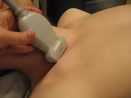 FIGURE 8.23. Transducer Positioning for a Supraclavicular Approach to the Subclavian Vein. The transducer is placed just superior and along the medial border of the clavicle. |
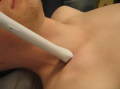 FIGURE 8.24. An Endocavitary Transducer may be Used in the Supraclavicular Approach Since it has a Smaller Footprint. |
Related posts:

Stay updated, free articles. Join our Telegram channel

Full access? Get Clinical Tree


