Musculoskeletal
Joy English
INTRODUCTION
According to the Centers for Disease Control, there are 2.6 million visits yearly to the emergency department (ED) for sports-related injuries, the majority of which are musculoskeletal in nature (1). This accounts for 1 in every 4 visits and, in the 5- to 24-year-old age group, equates to 33.9 visits per 1000 persons. Radiologists and physiatrists have utilized ultrasound to diagnose musculoskeletal pathology for >50 years (2). Ultrasound is becoming the most widely used modality in the evaluation of tendon pathology even when other advanced imaging modalities are readily available (3). Ultrasound is also the first mode of imaging available for muscle evaluation and remains the most useful modality to follow muscular trauma over time (4). Ultrasound use has continued to expand, particularly in the pediatric population, in part due to physician and public awareness of the negative effects of radiation exposure from computed tomography (CT) scanning (5).
In the emergency medical care setting, musculoskeletal ultrasound has been used in the evaluation of military personnel during combat, athletes on the sideline, and patients in remote settings with little or no access to standard imaging techniques. In the ED setting, musculoskeletal ultrasound has been shown to reduce the time to diagnosis, assist with difficult diagnoses, improve outcomes, and increase physician ease with musculoskeletal procedures (6, 7, 8, 9, 10).
CLINICAL APPLICATIONS
Ultrasound can be used to diagnose acute traumatic musculoskeletal pathology including fractures, joint effusions, and tears of tendons, ligaments, and muscles. It can also facilitate the diagnosis of acute inflammatory and infectious musculoskeletal pathologic states such as arthritis, tendinitis, tenosynovitis, myositis, and bursitis. Lastly, a number of musculoskeletal procedures can be performed with the aid of ultrasound guidance.
IMAGE ACQUISITION
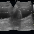
Evaluation of musculoskeletal pathology is typically performed with a high frequency (5 to 17 MHz) linear array transducer. The majority of ultrasound systems used in ED practice provide 5 to 12 MHz transducers for general-purpose imaging (Fig. 21.1A). Less often, a low-frequency (3 to 5 MHz) curvilinear transducer can be used when imaging structures, such as the hip, that are >4 to 5 cm deep (Fig. 21.1B).
Unlike imaging for other applications, the evaluation of musculoskeletal structures does not always include a landmark approach. Instead, the probe should be placed directly over the suspected site of pathology or the patient’s point of maximal tenderness. The area should be examined in a
systematic manner that includes views in the longitudinal and transverse axes. The evaluation of fractures additionally includes visualization of the anterior and posterior cortices (Fig. 21.2). It is common to scan the contralateral unaffected side to obtain images that can be used as a comparison in cases where questionable sonographic findings are encountered.
systematic manner that includes views in the longitudinal and transverse axes. The evaluation of fractures additionally includes visualization of the anterior and posterior cortices (Fig. 21.2). It is common to scan the contralateral unaffected side to obtain images that can be used as a comparison in cases where questionable sonographic findings are encountered.
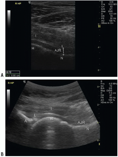 FIGURE 21.1. Transducer Differentiation in Hip Imaging. A: High frequency linear transducer showing excellent resolution in the near field. I, iliopsoas; H, femoral head; AJR, anterior joint recess; N, femoral neck. B: Low frequency curvilinear transducer showing poor resolution in the near field but improved penetration into deeper structures. A, acetabulum; L, labrum; I, iliopsoas; H, femoral head; AJR, anterior joint recess; N, femoral neck. |
Musculoskeletal ultrasound presents a few unique challenges to the sonographer. First, most musculoskeletal structures are superficial, and the abnormal contour of the skin surface makes maintaining transducer scanning surface contact difficult. Second, certain musculoskeletal ultrasound evaluations, such as flexor tendon laceration assessment, involve longitudinal visualization during range of motion, which is difficult when the transducer is placed on the flexor surface of the finger. Lastly, the suspected site of pathology is often exquisitely painful, making direct transducer contact uncomfortable. A few measures can be taken to combat these difficulties. First, a modest amount of ultrasound gel should be placed between the transducer and the structure of interest. If this does not yield an adequate image, a water bath immersion or a stand-off pad may be helpful (Fig. 21.3). Water bath immersion becomes an important tool when the area of interest has abnormal contours, a small surface area for probe contact, and is painful to the patient, such as tendon assessment in a finger or toe. Both the transducer and the area requiring examination are placed in a shallow basin filled with water. The water then acts as a medium to conduct ultrasound waves to and from the area of interest without interruption. The technique has been shown to improve image quality without increasing patient discomfort (11).
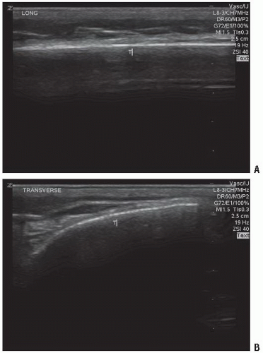 FIGURE 21.2. Evaluation of Musculoskeletal Structures. A: Tibia long axis. B: Tibia short axis. T, Tibia. |
NORMAL ULTRASOUND ANATOMY
Cortical Bone
Cortical bone appears as a bright (hyperechoic) line that is continuous without disruption (Fig. 21.4A, B). It should appear the same in both the long and short axes with notable posterior acoustic shadowing seen in the far field of the image due to the densely calcified cortex.
When evaluating cortical bone, the soft tissue directly adjacent to the bone should also be thoroughly examined. The overlying soft tissue should appear homogeneous (Fig. 21.4C). If clinical concern exists for a fracture in the presence of normal or indeterminate plain radiographs, any soft tissue abnormality, although nonspecific, is considered pathologic and should prompt further investigation or treatment.
 PEDIATRIC CONSIDERATIONS: In children, the evaluation of bone is more complex due to open physes, which may easily be mistaken for a fracture. An open physis appears as a smooth line that curves downward from both directions and occurs in the expected, more distal sites of the bone. In contrast to an acute fracture, it does not have an abrupt step-off (Fig. 21.4D).
 In cases of questionable sonographic findings, comparison plain radiographs should be obtained.

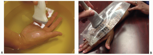 FIGURE 21.3. Adjuncts to Obtain Appropriate Images. A: Water bath immersion. B: Stand-off pad. |
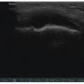
Tendon
Tendons have a characteristic homogeneous echogenic fibrillar appearance that represents collagen fibers running in parallel. They are more dense and echogenic than muscle. They should appear continuous without disruption and are best visualized in the long axis (Fig. 21.5A, B;  VIDEO 21.1).
VIDEO 21.1).Tendons exhibit a phenomenon unique to musculoskeletal imaging: anisotropy. Anisotropy is an artifact that occurs when imaging tendons, ligaments, and nerves with a linear transducer. These structures are optimally imaged parallel to the transducer, but when the angle of incidence and reflection are
not the same, they can appear dark or indistinct (Fig. 21.5C). This occurs most often at the tendon insertion sites and is a normal finding. The artifact should resolve with either angling the transducer or with muscle contraction, which will alter the axis of the tendon (Fig. 21.5D) (3). While anisotropy should resolve with repositioning, the appearance of a tendon tear or rupture will remain the same regardless of transducer position (12).
not the same, they can appear dark or indistinct (Fig. 21.5C). This occurs most often at the tendon insertion sites and is a normal finding. The artifact should resolve with either angling the transducer or with muscle contraction, which will alter the axis of the tendon (Fig. 21.5D) (3). While anisotropy should resolve with repositioning, the appearance of a tendon tear or rupture will remain the same regardless of transducer position (12).
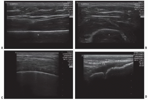 FIGURE 21.4. Cortical Bone Evaluation. A: Humerus in long axis with posterior acoustic shadowing. H, humerus. B: Humerus in short axis. C: Normal soft tissue overlying rib. D: Normal open tibial physis at the level of the knee in a child. PT, patellar tendon. |
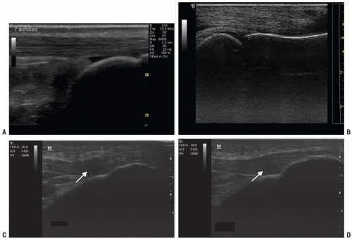 FIGURE 21.5. Tendon Evaluation. A: Normal Achilles tendon proximal to insertion. B: Normal flexor digitorum profundus. C: Normal tendon showing anisotropy in the patellar tendon insertion. D: Normal tendon showing corrected anisotropy in the patellar tendon insertion. |
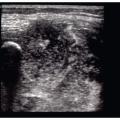
Skeletal Muscle
Skeletal muscle appears as groups of hypoechoic fibers separated by hyperechoic lines of fascia. In the longitudinal axis, these units represent perimysium encasing individual muscle fascicles oriented parallel to one another (13). In the transverse axis, muscle fibers appear as distinct groups that are separated by fascial lines (Fig. 21.6;  VIDEO 21.2).
VIDEO 21.2).Joints
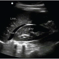
The joint space is comprised of the bones and surrounding periarticular structures, including tendons, ligaments, and muscle. The normal joint space is lined by synovium and filled with a small amount of anechoic fluid (Fig. 21.7). When the joint space is distended, ultrasound can help to objectively measure the size and extent of the effusion and characterize the nature of the fluid (14). The generally accepted measurements for a normal amount of fluid is defined for each joint (Table 21.1). The general appearance of pathological effusions include distension and bowing of the joint capsule. In most cases, comparison with a normal contralateral side can be used as a standard.
Ligaments
PATHOLOGY: TRAUMA
Bone
Acute traumatic fracture
Fractures are identified as a discontinuity or irregularity of the bony cortex (Fig. 21.10;  VIDEO 21.3). The abnormality should be visualized in both the long and the short axis and may appear as a small divot in the bone, a step-off, or a distortion of the entire cortex. Ultrasound detection of long
bone fractures has been studied in the adult and pediatric literature, and sensitivity remains 89% to 95% with specificity ranging from 85% to 100% when compared to plain radiographs (16,17). Ultrasound has greatest sensitivity in identifying long bone and midshaft fractures as compared to smaller bones and more distal sites (17,18). With regard to specific bones, ultrasound has proven useful in the evaluation of acute scaphoid fractures where initial plain radiographs are indeterminate or nondiagnostic and is superior to plain radiographs in evaluating rib fractures (7,8,19). Studies have also shown a significant reduction in mean time to diagnosis of fracture as well as a decrease in mean pain scores during the diagnostic procedure when compared with plain radiography (6). PEDIATRIC CONSIDERATIONS: In addition, ultrasound can be used to narrow the area of interest in children who are often unable to localize the area of pain. They may simply limp or refuse to use an arm and state the entire extremity hurts. Limiting radiographs to regions with definitive or suspicious ultrasound findings may reduce radiation exposure.
VIDEO 21.3). The abnormality should be visualized in both the long and the short axis and may appear as a small divot in the bone, a step-off, or a distortion of the entire cortex. Ultrasound detection of long bone fractures has been studied in the adult and pediatric literature, and sensitivity remains 89% to 95% with specificity ranging from 85% to 100% when compared to plain radiographs (16,17). Ultrasound has greatest sensitivity in identifying long bone and midshaft fractures as compared to smaller bones and more distal sites (17,18). With regard to specific bones, ultrasound has proven useful in the evaluation of acute scaphoid fractures where initial plain radiographs are indeterminate or nondiagnostic and is superior to plain radiographs in evaluating rib fractures (7,8,19). Studies have also shown a significant reduction in mean time to diagnosis of fracture as well as a decrease in mean pain scores during the diagnostic procedure when compared with plain radiography (6).
PEDIATRIC CONSIDERATIONS: In addition, ultrasound can be used to narrow the area of interest in children who are often unable to localize the area of pain. They may simply limp or refuse to use an arm and state the entire extremity hurts. Limiting radiographs to regions with definitive or suspicious ultrasound findings may reduce radiation exposure.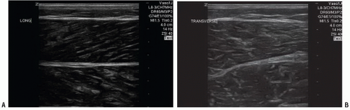 FIGURE 21.6. Muscle Evaluation. A: Normal gastrocnemius and soleus muscle in long axis. B: Normal gastrocnemius and soleus in short axis. |
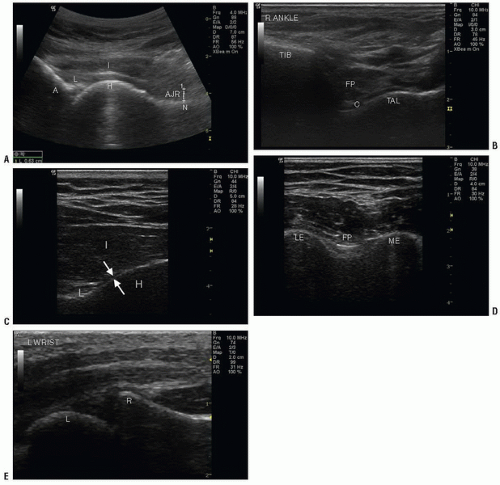 FIGURE 21.7. Joint Evaluation. A: Normal hip. I, iliopsoas; H, hip; L, labrum; A, acetabulum; AJR, anterior joint recess. B: Normal ankle. Tib, tibia; Tal, talus; C, cartilage and collapsed anterior joint recess; FP, fat pad. C: Normal shoulder—posterior joint recess. I, infraspinatus; H, humeral head; L, labrum. D: Normal elbow—posterior joint recess. L, lateral epicondyle; FP, fat pad; M, medial epicondyle. E: Normal wrist—volar joint recess. L, lunate; R, radius. |
TABLE 21.1 Normal Joint Space Size (mm) | ||||||||||||||||||||||||||||||||||||||||||||||||||||||
|---|---|---|---|---|---|---|---|---|---|---|---|---|---|---|---|---|---|---|---|---|---|---|---|---|---|---|---|---|---|---|---|---|---|---|---|---|---|---|---|---|---|---|---|---|---|---|---|---|---|---|---|---|---|---|
| ||||||||||||||||||||||||||||||||||||||||||||||||||||||
Related posts:

Stay updated, free articles. Join our Telegram channel

Full access? Get Clinical Tree


