CT scanning

Chapter 38 CT scanning


38.3 The development of the CT scanner


The first generation of CT scanners was of the translate–rotate type. A single source consisting of a finely collimated pencil beam was focused on a single detector that moved on a frame in a transverse direction across the body, the gantry on which the source and detector was mounted then rotated through 1° and another transverse movement was made. As can be imagined, this was a very slow process requiring approximately 5 minutes to produce a single slice. This restricted scanning to the demonstration of skeletal structures and soft tissues in which movement did not take place.


The second-generation scanners were still of the translate–rotate type. These used a fan-shaped beam and an arc of about 30 detectors. To compensate for the reduced beam attenuation at the periphery of the body, a ‘bow tie’ filter was placed between the source and the patient. The increased area covered in each translation and by the arc of detectors permitted rotation of 10° on each rotation producing a substantial reduction in the time per slice. However, because of the complexities of the translation–rotation movement, and due to the mass to be moved in the gantry, imaging times were still in the order of 2 seconds per slice.


The third-generation scanners were known as the rotate–rotate design. The width of the radiation beam and the arc of the detectors was increased to 60°. The geometry of the detector arc produced a constant source to detector distance, an advantage in image reconstruction, and also permitted better beam collimation reducing scatter formation. The increased detector arc had the effect of reducing time per slice to the order approximately 1 second, substantially reducing the risk of motion artifacts. The one major disadvantage with this system was that the failure of a single detector would result in the production of a ‘ring’ artefact. This could often be corrected by the image processing software.


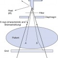
The current (fourth-generation) scanners (see Figure 38.1) have what is sometimes termed a stationary–rotate geometry, in which the X-ray tube rotates within a stationary circle of detectors. The earlier sodium iodide scintillation detector linked to a photomultiplier tube has been replaced by ceramic scintillation detectors. These detectors have a better response to radiation of the energy range used in CT. The photomultipliers have been replaced by solid-state photodiodes. The photodiode is far smaller than the photomultiplier tube and requires considerably less power to operate.


The reduction in size has permitted the detectors to be arranged in a continuous circular array containing as many as 40 000 individual detectors while the X-ray tube rotates around the patient within the circle of detectors. Fourth-generation systems are free from the ring artefact problem associated with third-generation scanners and are capable of subsecond slice production times.


The medium-frequency generator has permitted the development of ‘slip ring’ technology. The low-tension supply is supplied to a stationary ring of contacts, while the high-tension (HT) transformer, rectification system and X-ray tube are mounted on a second ring which rotates about the stationary ring. This innovation has eliminated the need for the X-ray tube to return to its starting position to commence another rotation.


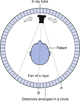
38.4 Scanner subsystems


38.4.2 The gantry


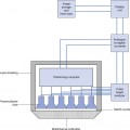
The gantry (see Fig. 38.1) consists of a large box-like structure with a central aperture through which the patient is passed during the scan. Within the gantry are the X-ray tube, HT transformer, rectification system, collimators, detectors and the motor drive and control system to move the X-ray tube during the scan.


Mar 6, 2016 | Posted by in GENERAL RADIOLOGY | Comments Off on CT scanning

Full access? Get Clinical Tree

Get Clinical Tree app for offline access