3.23: Dental radiology
Akshay A. Shah, Harpreet Kaur Gandhoke
Abbreviations
Introduction
Dental Radiology is a unique part of head and neck imaging and involves specific imaging techniques and interpretation.
Radiographic examinations are one of the primary diagnostic aids used in dentistry to identify disease and formulate an appropriate treatment plan. The radiographic diagnosis of disease requires the adequate knowledge of the radiographic appearance of normal structures. A good diagnosis requires appreciation of a wide range of variation in the appearance of normal structures. Most patients show most of the normal radiographic landmarks, but it is rare for a patient to show them all. Hence, the absence of one or several landmarks in any individual should not be necessarily termed abnormal.
Radiographic interpretation is the process of recognizing the apparent details on the radiograph, which aids in the identification of diseases, lesions and conditions that are not clinically identifiable.
‘Interpretation refers to an understanding of what is seen on the radiograph’, which leads to ‘diagnosis that is the recognition of disease by examination or analysis’.
A diagnosis is made by the dentist after a complete review of medical and dental history, clinical examination, radiographic evaluation and clinical or laboratory tests.
The commonly used imaging techniques are
Panoramic radiograph (OPG)
Panoramic radiograph is a technique for producing a single tomographic image of the facial structures that includes both maxillary arch and mandibular arch and their supporting structures. It is a curvilinear variant of conventional tomography and based on the principal of the reciprocal movement of an X-ray source and an image receptor around a central point or plane called the image layer in which the object of interest is located.
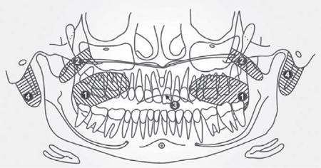
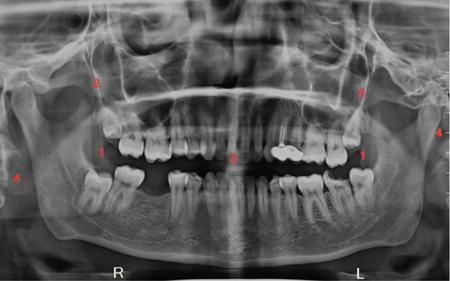
Anatomical landmarks on a panoramic radiograph
Normal landmarks seen on the panoramic radiography may seem different from machine to another, but generally, they may subdivide into:
(An additional real shadow is often casted by the vertical plastic head supports).
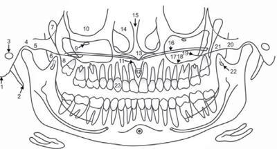
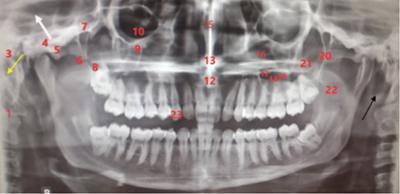
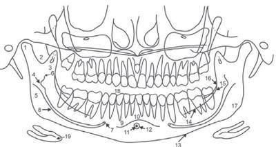
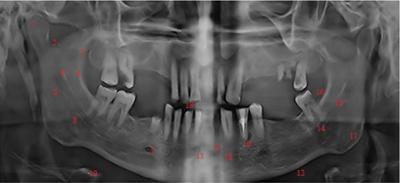
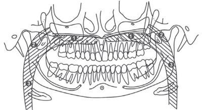
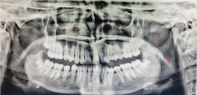
Outline of the anatomical landmarks seen in the maxillary region (Figs. 3.23.1–3.23.8)
Intraoral radiography
Intraoral dental radiographs fall into two main categories: bitewings and periapical radiographs. Bitewing radiographs are the best diagnostic tool available for the detection of interproximal caries and assessment of alveolar bone levels. Bitewings are used in the posterior regions of the mouth. Periapical radiographs record the entire tooth and supporting bone and are in use to evaluate the extent of caries and periodontal bone loss and aid in the diagnosis and treatment of root and bony pathology. Periapical radiographs and bitewings are in combination to form surveys of varying configurations, for a comprehensive view of the entire dentition. Intraoral radiographs can be captured using film or digital receptors. Digital receptors are available as wired and wireless rigid sensors (CCD—charge-coupled device; CMOS—complementary metal oxide semiconductor) and photostimulable phosphor plates.
Intraoral radiographs are a key tool in diagnosis as it gives minute and fine details leading to diagnosis.
Normal tooth anatomy (Fig. 3.23.9)
The radiographic appearances of structures observed on the intraoral periapical radiograph are:
Normal anatomical landmarks observed on the intraoral periapical radiographs may be classified as2:
Radiopaque
- A. Maxilla B. Mandible
- 1. Enamel 1. Enamel
- 2. Dentin 2. Dentin
- 3. Cementum 3. Cementum
- 4. Lamina dura 4. Lamina dura
- 5. Alveolar crest 5. Alveolar crest
- 6. Cancellous bone 6. Cancellous bone
- 7. Nasal septum 7. Genial tubercles
- 8. Anterior nasal spine 8. Mental ridge
- 9. Floor of the nasal cavity 9. Mylohyoid ridge
- 10. Inferior nasal conchae 10. External oblique ridge
- 11. Nasolabial fold 11. Inferior border of the mandible
- 12. Floor of the maxillary sinus 12. Coronoid process
- 13. Septa in maxillary sinus 13. Internal oblique ridge
- 14. Inverted Y in maxillary sinus
- 15. Zygomatic process of maxilla
- 16. Zygoma (malar bone)
- 17. Pterygoid plates
- 18. Hamular process
- 19. Maxillary tuberosity
- 1. Enamel 1. Enamel
Radiolucent
- A. Maxilla B. Mandible
- 1. Pulp 1. Pulp
- 2. Periodontal ligament space 2. Periodontal ligament Space
- 3. Nutrient canals 3. Nutrient canals
- 4. Intermaxillary suture 4. Lingual foramen
- 5. Nasal fossa 5. Symphysis
- 6. Incisive foramen 6. Mental fossa
- 7. Superior foramina of nasopalatine canal 7. Mental foramen
- 8. Incisive fossa (lateral or cranial) 8. Mandibular canal
- 9. Nasolacrimal canal 9. Mandibular fossa
- 10. Maxillary sinus
- 11. Nose
- 1. Pulp 1. Pulp
Normal anatomical landmarks seen on the intraoral periapical radiographs are classify as:
Supporting structures
Maxilla
Nose
Maxillary Sinus
Mandible
Supporting structures
Lamina dura, meaning hard layer, refers to the thin layer of dense bone that encircles the tooth sockets of a healthy tooth in an arch. Radiographically, it appears as a thin radiopaque layer (Fig. 3.23.10).
This layer is in continuation with the shadow of the cortical bone at the alveolar crest.
The alveolar crests are visible as radiopaque lines between the gingival margins of the alveolar processes of adjacent teeth (Fig. 3.23.11). The normal level of the crest is not more than 1.5 mm from the cemento-enamel junction of the adjacent teeth.
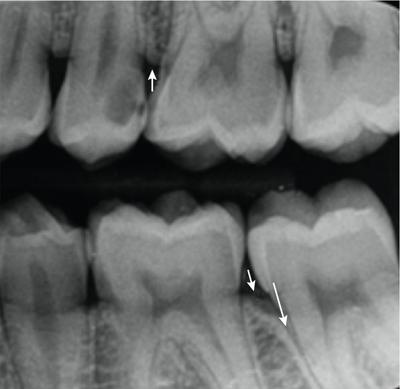
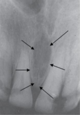
PDL is composed primarily of collagen; hence, it appears as a radiolucent space between the tooth root and the lamina dura. This space is visible from the alveolar crest on one side extending around the tooth roots within the alveolus and then returning to the alveolar crest on the opposite side of the tooth (Fig. 3.23.12).
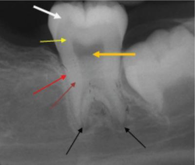
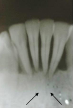
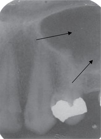
The cancellous bone (also called Trabecular bone or Spongiosa) occupies the space between the cortical plates in both maxilla and mandible. It is composed of thin radiopaque plates and rods (trabeculae) encircling many small radiolucent marrow spaces. The radiographic pattern of the trabeculae is deriving from the cancellous bone and the endo-osteal surface of the outer cortical bone (Fig. 3.23.13).
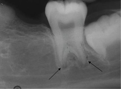
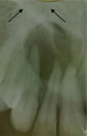
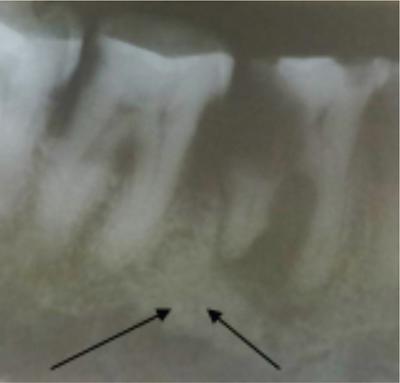
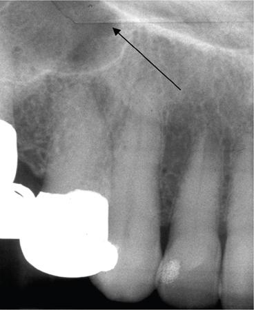
Trabecular plates (arrow) and larger marrow spaces than in the anterior maxilla (Figs 3.23.14 and 3.23.15).
Maxilla
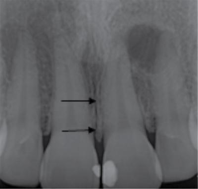
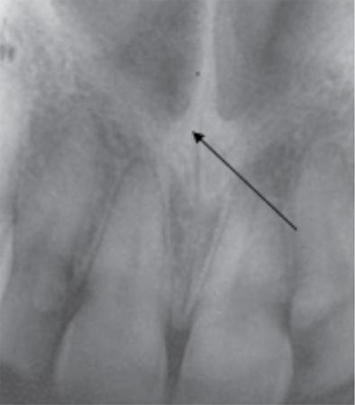
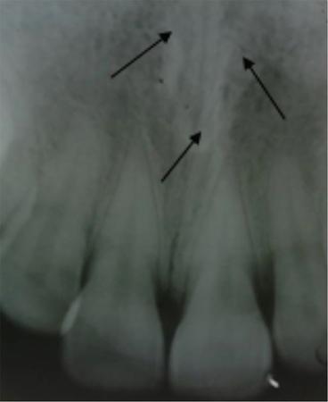
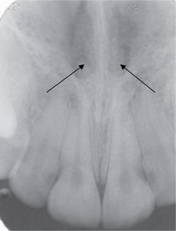
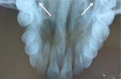
The two halves of the premaxilla fuse along the midline forming the intermaxillary suture or the median suture which is visible on an intraoral periapical radiograph as a thin radiolucent line (Fig. 3.23.16). It is visible along the alveolar bone between the central incisors passing through the anterior nasal spine, posteriorly between the palatine processes ending into the posterior aspect of the hard palate.
It is common for this narrow radiolucent suture to end in the alveolar crest in a small rounded or V-shaped widening. The other name for intermaxillary suture is the midpalatine suture (Fig. 3.23.17).
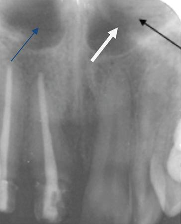
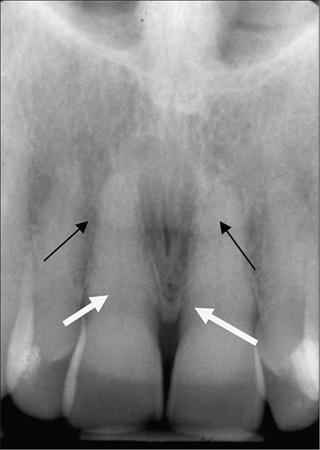
Intraoral radiographs of the maxillary teeth (especially the central incisors) show a radiolucent air-filled nasal aperture and nasal cavity that lie just above the oral cavity. A radiopaque line is visible on the inferior border of the fossa and aperture extending bilaterally distal to the base of the anterior nasal spine in periapical radiographs (Fig. 3.23.18). Above this line is the inferior portion of the nasal cavity seen as radiolucent space on the radiograph. A radiograph projecting in the sagittal plane shows the relatively radiopaque nasal septum placed superior to the anterior nasal spine (Figs. 3.23.19 and 3.23.20).
The nasopalatine canal terminates into the incisive foramen (also called the nasopalatine foramen or anterior palatine foramen) in the anterior floor of the nasal fossa in the maxilla. The contents of the foramen are the nasopalatine vessels and nerves (which may innervate the maxillary central incisors) and lie along the midline behind the central incisors approximately at the junction of median palatine suture and incisive sutures. The radiographic image is projecting in the middle and apical third regions of the roots of central incisors. Incisive foramen is of significance as cyst formation is common in this region. An incisive canal cyst is radiographically, recognized as it causes enlargement of the foramen and canal. Evaluation of these structures is important when an implant insertion is considered (Fig. 3.23.21).
The two foramina in the floor of the nasal cavity give rise to superior foramina of nasopalatine canal. It opens bilaterally to the nasal septum, near the antero-inferior border of the nasal cavity. It is passing downward anteriorly and medially to join and form a common opening, the incisive (nasopalatine) foramen. The superior foramina of the canal are rarely visible in sharply angled projections of the maxillary incisors (Fig. 3.23.22).
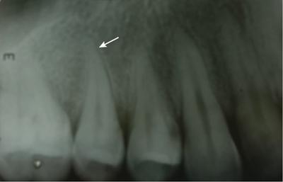
The apex of the maxillary lateral incisors shows a depression in the cortical bone known as the lateral fossa (Fig. 3.23.23). It appears as a diffuse radiolucency visible on a periapical radiograph.
The soft cartilaginous tip of the nose is mostly visible as a uniform, slightly radiopaque region with a well-defined border in the radiographic projections of the maxillary central and lateral incisors, superimposed over the roots of these teeth (Fig. 3.23.24).
The nasal and maxillary bones form the nasolacrimal canal and it courses from the medial side of antero-inferior border of the orbit to drain under into the nasal cavity. Occasionally, it can be visible on a sharply angled periapical radiograph of the canine (Figs 3.23.25 and 3.23.26).
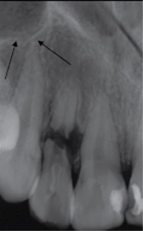
The maxillary sinus is the largest paranasal sinus occupying virtually the entire body of maxilla. It is an air-filled cavity lined with mucous membrane. It develops because of invagination of mucous membrane from the nasal cavity. The sinus may be consider as a three-sided pyramid, medial wall adjacent to the nasal cavity as base and its apex extending laterally into the zygomatic process of the maxilla. The sinus connects to the nasal cavity with an opening of about 3–6 mm passing through the middle concha of the ethmoidal bone. Periapical radiographs of the canine show the floors of the sinus and nasal cavity superimposed on one another, forming an inverted ‘Y’ in the area (Figs 3.23.27 and 3.23.28).
Related posts:

Stay updated, free articles. Join our Telegram channel

Full access? Get Clinical Tree


