Fig. 7.1
The original model U GK unit as installed in the USA in the late 1980s. (a) The side view of the unit and couch; (b) the helmet collimator with a head phantom docked onto the helmet via the attached stereotactic frame
In 2006, Elekta introduced a new GK unit called Perfexion (PFX). The PFX (Fig. 7.2) transforms and significantly improves upon the design of previous GK models. One distinct feature is the use of a single collimator where three sizes of collimation apertures (16, 8, and 4 mm) are drilled directly into a single piece of tungsten shaped like a speaker cone. The radioactive 60Co sources are placed inside metal housings called sectors that slide linearly on the outer surface of the collimator to align themselves with these predrilled apertures, to create confocal radiation beams of 16, 8, and 4 mm of approximate full width half maximum (FWHM). Because the sectors are driven by independent stepper motors, beams of different aperture sizes can be mixed from different directions at the focus point. The total number of configuration for variable beam apertures at the isocenter is given as 48 − 1 = 65,535. This is because at each isocenter, a total of four beam aperture sizes (0 mm or blocked, 4, 8, and 16 mm) can be directed from eight equally spaced directions, i.e., 45° separation between two neighboring sectors surrounding the universal collimator. The overall beam precision is dependent upon the precise drilling of >500 apertures and the precise alignment of the sliding sectors. Therefore, manufacturing the universal collimator and sector housing comprises a major cost in building the PFX unit.

Fig. 7.2
The redesigned PFX unit as released by Elekta in 2006. Note the absence of helmet collimator and the universal collimator design as compared with the original Model U of Fig. 7.1
Besides elimination of the tertiary helmet collimators with a single universal collimator, the new PFX design also transforms the automatic patient positioning system (APS) via the introduction of a single integrated translational couch. Therefore, independent patient positioning devices such as the tertiary trunnion bars and add-on APS units have been eliminated. The translational couch enables the patient’s head frame to be docked onto the end of couch and then entire patient body plus the head frame is shifted automatically to align with the treatment delivery. The maximum tolerance level for the accuracy of the translational couch is less than 0.3 mm, which is comparable to the previous models.
The elimination of the tertiary collimator has also significantly extended the maximum traveling distance achievable for the PFX as compared to the previous models. For example, the overall reachable volume via the automatic couch has been extended more than 300 %. Now the majority of intracranial lesions can be readily treated with the stereotactic frame placed in the central position, this greatly eases the effort of frame placement.
This new design of the Gamma Knife PFX has resulted in a simple turn-key solution for most treatment indications including complex multiple metastatic brain lesion treatment with significant improvements in the range of locations in the brain that can be treated, radiation safety, and patient comfort.
In addition to the above hardware design improvements, the treatment planning system for the PFX has also been updated from the previous models. The salient features of the system as well as the 3D dose calculation algorithms are covered in another chapter.
Linear Accelerator-Based SRS Units
Historically, linac-based SRS units were built upon standard linear accelerators with add-on collimation systems and couch stabilization devices [16, 22–32]. The majority of these SRS units employed tertiary cones, or add-on micro- or mini-multileaf collimators, to deliver noncoplanar converging arc beams at the isocenter. The arrangement of these noncoplanar arc beams aims to deliver an elliptical dose distribution similar to that of a single shot in Gamma Knife delivery. In general, the tertiary cones are made from high-Z materials and are intended to extend the source to diaphragm distance to sharpen the beam penumbra at the isocenter. Note that the source to isocenter distance is typically 100 cm, which is more than two times of the source-to-isocenter distance of the GK unit.
Unlike GK units where the isocenter is mechanically aligned with the beam focus, traditional linac-based SRS units predominantly rely on wall-mount lasers and special localizer boxes attached to the stereotatic frame for defining the target coordinates. Therefore, the accuracy of the laser system is critical in ensuring the treatment accuracy for linac-based SRS units. As a general practice, a pretreatment isocenter alignment check must be carried out for each patient delivery.
Figure 7.3 illustrates the isocenter alignment devices for the PFX unit. In using the isocenter alignment check tool, the beam profile is first scanned via small-volume detector such as diode (Fig. 7.3a) across axis directions. A film is pricked with a pin at the isocenter set by the mechanical device (Fig. 7.3b). Then the film is exposed and pinprick mark is compared with the center of the beam profile to determine agreement between the mechanical and radiation isocenters [5, 25, 30, 33, 34].

Fig. 7.3
Example of isocenter test tools: (a) an automatic diode scanning tool; (b) a film holder with central prick pin for marking the film before exposure with the radiation
For linac-based SRS units, the most commonly used isocenter alignment check is the Winston–Lutz test method [28, 32]. For the test, a metallic spherical ball is first aligned with the isocenter using wall-mount lasers or a front-pointer. A series of port films are then exposed downstream for a “dry-run” of actual beam deliveries. Typically, the film is placed on a special holder attached to the gantry port extending underneath the ball. If the linac is equipped with high-resolution electronic portal imager (EPID) [35], the image can be taken with that device in lieu of the film. Once exposed, the projected ball image is compared with the edge field to detect any deviations in the isocenter. The Winston–Lutz test is especially useful for linac-based SRS because it not only checks the isocenter alignment but also detects any collisions among the gantry, couch, and tertiary collimators during the patient delivery.
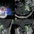
Example isocenter measurement results for a Gamma Knife unit and a linac-based SRS unit are given in Fig. 7.4.

Fig. 7.4
Results of radiation and mechanical alignment tests for (a) GK unit and (b) linac-based SRS unit. (a) Used the smallest circular field of 4-mm in diameter and (b) used a square field of 4 × 4 cm2. The agreement between the pinpricked center and full width half maximum (FWHM) field edge was found to be within 0.5 mm for both cases
Once the alignment between the laser and mechanical isocenters is verified, the target coordinates for the linac-based SRS treatments are set via a laser-based localizer. A picture of the setup localizer is shown in Fig. 7.5. To facilitate the alignment of the isocenter, the localizer can be adjusted in six degrees of freedom (x, y, z translation, and pitch, yaw, and roll) to correct for non-flat couch top and minor setup errors. The coordinates on the localizer is commonly set in positive numbers in order to minimize misreading in setting up the stereotactic coordinates.

Fig. 7.5
A typical linac-based SRS treatment setup and illustrated beam arrangements
With the recent advent of onboard imaging devices, the isocentric process has been gradually replaced by automatic image-based setups. An example of such a new generation linear accelerator is shown in Fig. 7.6. Some of the features of this type of linear accelerator include digital control boards, an onboard imager (OBI), high dose rate delivery without flattening filter attenuation as used for conventional radiotherapy. With an improved digital control system, such a linear accelerator is able to deliver arc beams with a high dose rate while being able to adjust the speed of gantry rotation and MLC leaf motions for beam intensity modulation, as well as collecting 2D and 3D onboard kV images during the process. As a result, patient treatment setup does not need to be referenced to the isocenter setup and verifications, but can solely rely on direct online image studies via OBI for direct planar or volumetric match of the patient position with that defined in the reference CT image studies during the treatment planning process. However, the imaging device must be carefully calibrated so that its reference center coincides with the linear accelerator isocenter, so that any shift in patient position detected from the online imaging process can be reliably compensated using changes in couch position or beam alignment (i.e., MLC shifts).

Fig. 7.6
A digitally controlled linear accelerator capable of high dose rate stereotatic radiosurgery, hypofractionated body radiotherapy, and conventional radiotherapy delivery as released by Varian Medical Systems in 2009
Once the patient is aligned, linac-based SRS commonly uses either noncoplanar converging fixed beams or dynamic arc beams. In dynamic rotation delivery, the gantry rotates while the couch can be either fixed or rotates at the same time. The advantage of the dynamic arc-beam delivery is that only a single treatment setup is required and parallel-opposed beams can be avoided during the entire delivery to produce a better entrance and exit dose for a treatment plan.
With the ubiquitous adoption of high-definition MLC systems, fixed-cone collimator-based SRS delivery is fast being replaced by MLC-based SRS delivery. From the beginning, these high-resolution MLCs were able to shape the beam aperture conformally in the beam’s eye view during the gantry rotation for linac-based SRS delivery; therefore, the technique is termed shaped-beam SRS delivery in contrast to the traditional fixed-beam cone SRS delivery [27, 29, 31, 36–38]. Recent advances in MLC technology have resulted in leaf size on the order of even 2.5 mm which allows for even small targets <1 cm to be treated.
For the majority of treatments, MLC-based SRS is capable of delivering the full treatment regardless of a single or multiple targets with a single isocenter. With optimized beam weights and intensity modulated arc beam delivery (IMAT or VMAT), MLC-based SRS may also be able to deliver even better dose distributions for complex targets as compared to the conventional fixed-field approach [31]. A picture of a dedicated MLC-based SRS linear accelerator is shown in Fig. 7.7. The unit is considered as a stereotactic unit because it possesses a high-definition MLC with a slightly restricted maximum field size of 22 × 40 cm2, as compared to the 40 × 40 cm2 maximum field size typical of conventional linear accelerators. In addition, this particular unit also possesses the capacity to perform online near real-time image guidance via a ceiling and floor-mounted kV X-ray imaging system. The mechanical accuracy of the unit has been reported to be on the order of 0.5 mm [39], and notably treated small targets such as the trigeminal nerve root entry zone for the treatment of trigeminal neuralgia [38].

Fig. 7.7
A dedicated linear accelerator unit Novalis (Brainlab Company) with a built-in high-definition 2.5 mm leaf width at isocenter MLC, for shaped-beam SRS delivery
Cyberknife SRS Unit
The Cyberknife consists of a compact linear accelerator mounted onto a robotic arm. The accelerator is collimated using fixed cones that range from 5 to 60 mm in nominal diameter. In newer units, an optional variable diameter collimator (Iris) can be used. Treatment is primarily guided using a pair of orthogonally mounted planar X-ray imagers, although the system also has an optional optical tracking system that can be used in conjunction with the X-ray imager.
Considering the principles of the design, Cyberknife is a unique SRS system in that the majority of the treatment beams are non-isocentric (Fig. 7.8). The largest circular field size for the Cyberknife is 6 cm in diameter so the system is by design a dedicated SRS unit. However like dedicated linac-based systems, cross firing and fast overlapping of multiple beams of variable field sizes allow the Cyberknife to treat larger target volumes such as the prostate.

Fig. 7.8
Illustration of the Cyberknife SRS unit with integrated kV imaging system
Unlike those isocentric systems previously discussed, several unique factors contribute to the successful operation of the Cyberknife [1]. The linear accelerator operates in the X-band microwave frequency which allows for a significantly shorter waveguide length and a compact design of the linear accelerator head such that it can be mounted onto a robotic arm. This facilitates non-isocentric beam delivery and, more importantly, precision handling of the linear accelerator to achieve the necessary accuracy required for SRS delivery [2]. The stereoscopic ceiling mount kV X-ray tubes provide sufficient fast 2D imaging to monitor the patient positioning, not only during the setup but also throughout the treatment, to constantly guide or correct the individual beam direction from the linear accelerator head beam to irradiate a target [3]. In-room kV X-ray images are able to match accurately (<0.1 mm) with digitally reconstructed images (DRRs) from a conventional CT scan to generate a virtual image center, which the robotic arm uses for guiding the individual beam directions. In essence, the image center is the heart and soul of Cyberknife delivery, and it can be placed anywhere in space as long as the robotic arm knows where it is. This is fundamentally different from all other SRS units, where the image center must reference to the mechanical isocenter of the linear accelerator and not vice versa.
Tomotherapy Unit
Tomotherapy is an integrated unit that is capable of delivering SRS using intensity modulated radiation therapy treatments based on a helical fan beam geometry analogous to modern CT scanners [15, 40]. In design, one can think of the Tomotherapy unit as a CT unit that also delivers therapeutic high-energy X-rays. The unit has a compact Siemens 6 MeV S-band linac mounted on a rotating slip ring gantry with a source–axis distance of 85 cm. The linac has neither a bending magnet nor a flattening filter and operates at a nominal dose rate of approximately 900 MU/min. The bore of the unit is >80 cm, and there are a series of individual binary (either open or shut) collimators that produce a fan-beam X-ray across the gantry. The binary MLC leaves open and close to modulate the beam direction in the transverse direction.
The size of the field in the longitudinal direction (parallel to the bore) is defined by a pair of jaws. The field size currently in the longitudinal direction is 1, 2.5, or 5 cm. During delivery, the patient is transported through the bore of the gantry as the fan-beam rotates around to form a spiral trajectory around the patient. The Tomotherapy unit is also equipped with 738 xenon detectors that enable online CT scanning of the patient using MV photons using the treatment beam. The unit is shown in Fig. 7.9. With binary collimation and online imaging capabilities, Tomotherapy delivers SRS treatments similar to the shaped-beam linac-based SRS treatments except the target volume is irradiated in a slice-by-slice fashion. The physical accuracy of the unit is on the order of 0.5–1.0 mm.

Fig. 7.9
Tomotherapy unit with built-in fan-beam megavoltage X-rays and online megavoltage CT capability for image guidance
For the specific application of high dose intracranial SRS treatments, one challenge for the Tomotherapy unit has been immobilization of the patient to correctly match that of reference position during the CT simulation process. Although patient roll angles can be corrected by changing the delivery angles, any significant rotational error in pitch and yaw in the patient setup must be corrected manually before the treatment. In addition, the existing Tomotherapy system does not have the ability to detect patient motion during delivery. Longer treatments can therefore be broken down into smaller sub-fractions to allow imaging to detect potential motion.
Overall Accuracy
Treatment accuracy has been the key characteristic of all SRS units. The mechanical accuracy is reported to be less than 0.3 mm for Gamma Knife, 0.5–1.0 mm for dedicated SRS linac units, 0.5–1.0 mm for Cyberknife and Tomotherapy units, and approximately 1.0 mm for linac-based non-dedicated SRS units. To evaluate the overall procedural accuracy of a SRS treatment (unless for a simple treatment geometry such as trigeminal neuralgia where mechanical accuracy can dominate), other sources of uncertainties must be carefully considered. These include (1) uncertainties in the diagnostic imaging studies and image fusion when applicable, (2) dose calculation uncertainties, and (3) target motion and setup errors. In general, the imaging resolutions of CT and MR studies and the spatial distortions in the imaging acquisition process are the major source of uncertainties intrinsic to all SRS units. For example, irregularities in the gradient field and the magnetic susceptibility from the stereotactic frame could cause significant spatial errors for the MR studies in SRS treatments. For dose calculations, the acceptance level of a SRS dose algorithm is <2 % or <1 mm in the high dose gradient regions.
Table 7.1 summarizes the estimated error levels for SRS deliveries.
Table 7.1
Estimated uncertainties in intracranial SRS deliveries in terms of a peripheral isodose surface conforming to a clinically defined target surface
Source of errors | Standard deviation (mm) |
|---|---|
Imaging studies (resolution and distortions) | 0.5–1.5 |
Mechanical alignment and setup errors | 0.3–1.0 |
Tissue/target motion | 0.5–1.0 |
Treatment planning | 0.5–1.0 |
Overall (quadrature) | 1.3−2.2 |
Overall, the imaging studies and setup variations can be the major sources of uncertainties in most SRS deliveries [41] but, nonetheless, the overall procedural accuracy can be conservatively estimated to be on the order of 1–2 mm or better.
Potential Issues and Challenges
Over the past decade, image-guided or image-based SRS delivery such as Cyberknife and linear accelerator systems have created a significant driving force to deliver more precise treatments with greater efficiency and patient throughput. One common challenge for existing image guidance solutions is to ensure that the imaging process is sufficiently fast. This is important not only for the purposes of treatment efficiency and patient comfort but also to ensure that any observed patient shifts can be corrected in a timely fashion before and during the beam-on delivery. However, frequent imaging via the current kV or MV X-ray beams has raised concerns with respect to excessive imaging dose and risks of secondary malignancies, particularly for young patients. One potential development is in the area of imaging modalities such as online MR-guided teletherapy treatment devices. Future studies will confirm whether such new developments would improve the overall accuracy and more importantly clinical outcome of such devices over the traditional SRS deliveries.
Shielding Design
One of major tasks in building and installing a SRS unit is to design a bunker room and to enforce radiation protection rules. There are two aspects of source shielding and radiation protection for SRS delivery: (1) to reduce extrafocal radiation that contributes to dose deposition outside of the target volume and (2) to reduce radiation exposure to the operators and the general public outside of the room.
The radiation to be shielded is generated from the primary beam directly hitting outside of the target, scattered radiations, and leakage radiation from the head of the radiation source. For extrafocal radiation irradiating the patient internally, the concern is secondary malignancy risk, particularly in the treatment of young patients and patients with benign diseases or functional conditions to which radiation is being applied. Measurements have been carried out to document such doses for both GK and linac-based SRS units [5, 42]. As a percentage of the target dose, GK and linac-based units result in ~0.4 % to blood forming organs, ~0.5 % to the thyroid, ~0.04 % to the gonads, and ~0.05 % to the breast or thorax region. One difference between the GK and the linac-based units is the dose to the lens. Since the d max for 60Co is 0.5 cm while for 4–6 MV is in the range of 1.0–1.5 cm, the lens dose is estimated to ~2.5 % of the target dose. Such a percentage could be important for treatment involving a large dose of delivery such as that for trigeminal neuralgia where the target dose ranges from 70 to 90 Gy.
For room shielding, the bunker design depends on numerous factors that include the machine load, how frequently a particular wall is irradiated, and the distance between the wall and the isocenter. To ameliorate requirements for primary irradiations, it is often advantageous to construct a bunker in the basement and direct the primary beam toward the underground earth. Figure 7.10 shows a sample floor plan hosting a SRS unit. As an illustration, we present here an example calculation for shielding design of the floor plan in Fig. 7.10.