Chapter 1 Digital imaging
Introduction
Advantages of digital images
• Image manipulation. Digital images consist simply of a matrix of pixels; as each pixel has a numerical value it is very easy to apply mathematical formulae to these values. The effect of such formulae is to change the appearance of the image to enhance or subdue certain image features. Examples of image manipulation are edge enhancement, noise smoothing, subtraction or windowing.
• Image transmission. The numerical values of the individual pixels making up an image can be represented by pulses of electrical current, light, microwaves or radio waves. Consequently, images can be sent via an array of transmission media such as phone lines, optical fibre or satellite, enabling remote diagnoses regardless of where the image was acquired.
• Image storage and compression. Images can be easily archived as numerical data on an array of storage media. Storing clinical information on digital media enables easy access to all relevant patient data. Producing images in digital format allows for the compression of images, meaning that less storage space is required and images are more easily transmitted.
• Image analysis or reconstruction. A range of analyses can be performed on images in digital format. Images can also be reconstructed to produce images quite different from the original sequence, e.g. 3D reconstruction in computed tomography (CT).
Computed radiography
CR is a cassette-based digital radiography system that uses photostimulable phosphors (PSPs) in combination with a plate scanning system to produce a digital image. First introduced in 1983,1 it became the dominant method of acquiring digital radiographs. Analogous to the rare earth phosphor screen technology of 1970–1990, CR uses alkaline-earth halides and alkaline halides as PSPs to record a latent image of any irradiated structure.
Components of a CR system
The CR imaging plate
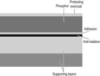
The layers that make up a typical CR plate are shown in Figure 1.1. The technology used is very similar to intensifying screen construction.
1 The top layer of the image plate is a thin protective layer. This layer is electron beam cured to reduce the amount of laser beam reflection that occurs during secondary excitation.
2 Directly beneath the protective layer is the PSP. The phosphor used is generally a barium fluorohalide with europium impurities, together known as europium-activated barium fluorohalide (BaFX : Eu). The most common of the halides used in storage phosphors are iodine and bromine (designated as X in the formula above). The thickness of the PSP layer and the flatness of the surface are factors associated with noise, noticed as mottle.2
3 The phosphor layer is attached to a dyed layer that is often described as the anti-halation layer. This layer stops or reduces the amount of laser light that is reflected back into the phosphor layer.
4 Underneath the anti-halation layer and part of the support polyurethane is a conductive layer which allows any static electricity to escape without causing damage to the image plate or stimulating the phosphor layer.
5 All of the above layers are supported by the support polyurethane backing layer, which provides rigidity for the whole structure. The polyurethane is also attached to a layer of laminate, which provides further support, and the complete image plate is stored inside a tough cassette for further protection.
The image reader
• Single plate image readers allow the operator to insert one image plate at a time. The plate is scanned, the image is extracted, any residual information on the plate is erased and the image plate is returned to the operator before the next image plate may be scanned. The operator must be present to remove the scanned cassette and place the next image plate into the reader. Single plate image readers are best used to serve one X-ray room, one operator, or ward or theatre area.
• Multiple plate image readers incorporate a buffer system that allows multiple image plates to be scanned. These buffer systems usually accept up to 10 image plates of any size at any one time, and incorporate an automatic image plate loading system. The operator can thus leave the exposed image plates in the buffer and return to their patient while the image plates are being automatically read. Multiloader systems are usually centrally located in the X-ray department and may service multiple X-ray rooms.
CR image formation
1 Primary excitation: X-ray photons incident on the imaging plate interact with the storage phosphor layer. The impurities in the PSP, typically europium, cause the formation of electron traps; it is the electrons in these traps that form the latent image. The number of trapped electrons is directly proportional to the number of photons incident on the storage phosphor plate. These trapped electrons are relatively stable, but some may be prematurely released by receiving sufficient energy from sources such as background radiation or heating. Fading of the trapped signal will occur exponentially over time, so it is important to read the plate as soon as practicable after exposure.3
2 Secondary excitation: The image reader removes the image plate from its cassette and transports it to the laser. The laser stimulates the phosphors in the image plate providing enough energy to release the trapped electrons that form the latent image. These electrons, once released, drop immediately to their resting state. This drop in energy releases electromagnetic radiation in the form of light. Light leaving the phosphor plate is directed towards the photomultiplier tube via optical coupling. This is normally achieved through the use of fibreoptic bundles.
3 Photomultiplication and erasure: The photomultiplier tube (PMT) creates an electrical signal proportional to the light incident on the photocathode. This electrical signal is then amplified and sent for digitisation. Once the laser has scanned the image plate and the photomultiplier has produced its signal, the image plate is then erased.
4 Digitisation: The electrical signal generated by the PMT is digitised by an analogue-to-digital converter (ADC). The ADC does this by converting the continuous electrical signal into in a digital signal in two steps, called sampling and quantisation.
