Chapter 10 Electromagnetic induction
Chapter contents
10.1 Aim
This chapter considers the laws of electromagnetic induction. The direction of the induced current will be identified. The concepts of mutual induction and self-induction will be discussed in preparation for Chapter 14, where the application of these will be considered in transformer design.
10.2 Introduction
In Chapter 9, we covered the topic of electromagnetism and this chapter deals with the topic of electromagnetic induction. As can be seen from the definitions below, one is just the reverse of the other. They may each be defined as follows:
10.3 Conditions necessary for electromagnetic induction
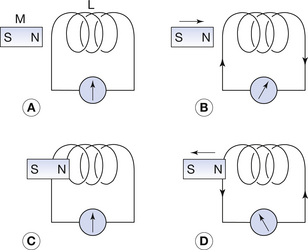
Consider the simple experiment depicted in Figure 10.1. A solenoid L is joined to a meter that can measure both the magnitude and the direction of the current flowing through the solenoid. The following effects are observed:
• No current flow is observed on the meter if the magnet is stationary with respect to the solenoid (Figure 10.1A and C).
• A current flows through the meter whenever the magnet is moved towards or away from the solenoid (Figure 10.1B and D).
• The magnitude of the induced current is greater if the magnet is moved faster.
• Reversing the direction of the movement of the magnet reverses the direction of the induced current (Figure 10.1B and D).
• Reversing the pole of the magnet, which is closer to the solenoid, reverses the direction of the induced current for a given movement.
From this simple experiment, we can conclude that only a changing magnetic field relative to the conductor is able to induce electricity in the conductor. We can also see that the amount of electricity produced is in some way related to the rate of change of the magnetic field relative to the conductor. Finally, we can conclude that the direction of movement of the magnetic field influences the direction of the induced current. These concepts will be discussed in more detail in the following sections of this chapter.
10.4 Faraday’s laws of electromagnetic induction
1. A change in the magnetic flux linked with a conductor induces an electromotive force (EMF) in the conductor.
2. The magnitude of the induced EMF is proportional to the rate of change of the magnetic flux linkage.
EMF was considered in Section 7.6 and can be considered as the force which is capable of causing electrons to flow (i.e. EMF will cause a current to flow in a complete circuit). It is important to note that Faraday’s laws do not specify whether or not the conductor is connected to an external circuit but, in either case, an EMF will be induced in it.
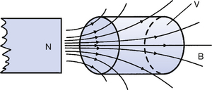
Magnetic flux and magnetic flux density are discussed in Chapters 8 and 39. The magnetic flux through a volume V can be visualized as being proportional to the number of lines of flux passing through that volume (Fig. 10.2). Thus, if a magnetic flux of 10 weber passes through V, then the magnetic flux linkage with V is also said to be 10 weber. If the magnet in Figure 10.2 is moved to the left of the page, then the number of lines of flux (or the flux linkage) in the volume V will be reduced.
10.5 Lenz’s law
In our initial observations regarding the induced current (Sect. 10.3) we noted the direction as well as the size of the current. Faraday’s laws apply to open or closed circuits but, as Lenz’s law concerns the direction of the induced current, it can only be applied to closed circuits. The law can be stated as follows:
