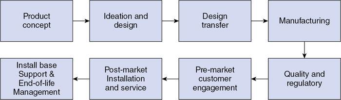
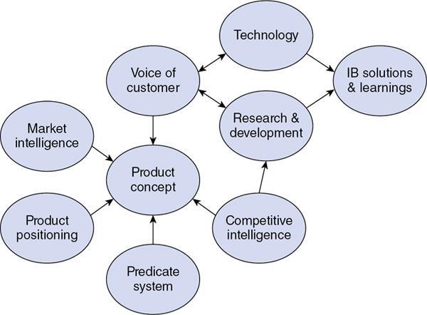
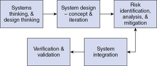
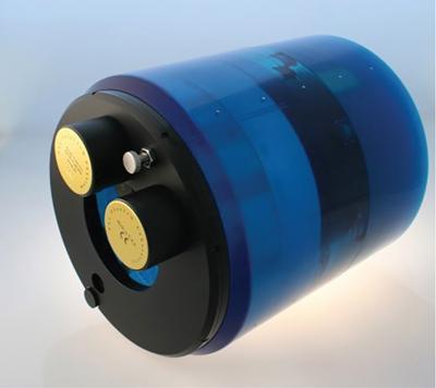
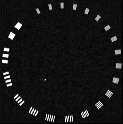
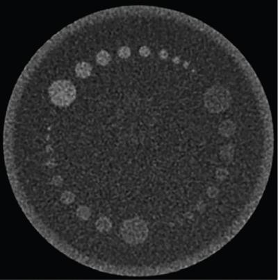
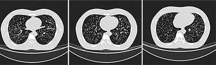
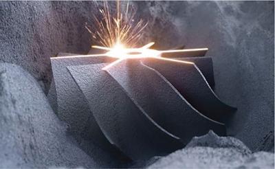
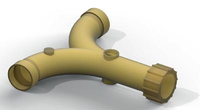
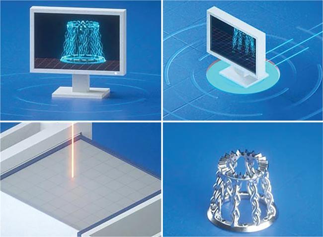
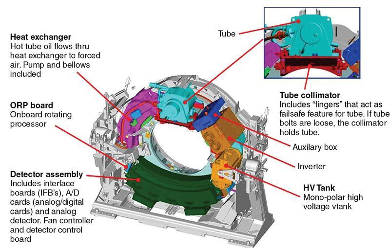
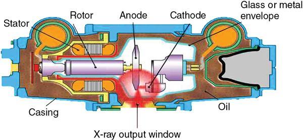
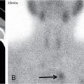
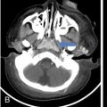
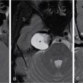
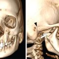
Srinivasa Varna, Padmashree G. K., Ramesh Venkatesan, Rajeev K, Ravinder Kaur, Bhairav Mehta Medical equipment for imaging modalities such as ultrasound, radiography, computed tomography (CT) and magnetic resonance imaging (MRI) fall under the ambit of diagnostic medical devices. These equipment offer themselves as noninterventional (more often) modes to image the human anatomy and thereby provide insights into the anomalies and ailments if any. It is therefore imperative that these devices aid the radiologists in providing quick and accurate diagnosis as well as prognosis of the underlying medical condition, to make pertinent recommendations for patient management. Most of these imaging devices play a vital role in moments of emergency owing to their ability to provide life-saving and critical noninterventional diagnosis. To this end, the capability, performance, quality and reliability of imaging devices are of utmost importance. They are perhaps the four pillars of any medical device, in general, and imaging device, in particular. While the underlying science in each of the imaging modalities and the basic principles of physics involved in image generation and presentation have not changed much over the past few decades, the engineering and processes involved therein, which is mostly behind the scenes for the end users of the product, serve as key differentiators across the major vendors. Sure enough, technology is another key differentiator. This chapter aims to give the readers, a seek-a-peek into the engineering stages, processes and standards that go into making a radiological equipment. In this chapter, we endeavour to introduce the readers to the product life cycle of an imaging device. In other words, we describe the journey of a product and milestones therein – all the way from ideation/concept to its end-of-life, as it rides through the engineering tollway. A typical product life cycle involves the following phases, as the product finds its way into its destination, which is the site of product deployment. While the first three phases form the first leg of the journey which is idea-to-factory, the second leg, which is factory-to-field journey, involves the phases postmanufacturing as shown in Fig. 1.36.1. This multiphase journey involves multiple stakeholders at every stage and is truly an exciting, enriching and rewarding one for all those that are involved, making the learnings invaluable. Envisaging a product is the first step to realizing a product. To this end, conceptualization is an imperative first step and forms the first phase of the product lifecycle. Well begun is well done! Therefore, this is a key step in the product development cycle, as it serves to make an impact on the entire spectrum of relevant stakeholders who cut-across areas spanning technology, end users and patients. Concept development is a process that warrants multidisciplinary inputs. This is vital to ensuring that the vendors of imaging equipment get the “right product” as opposed to getting only a “product right”, while the latter is a crucial internal checkpoint. The ecosystem that is vital to providing key inputs for conceptualization of a product is depicted in Fig. 1.36.2. There is a very close interplay between voice-of-customer (VOC), research, technology and install base (IB) solutions/learnings, which is apparent from the above schematic. It would be appropriate to mention at this point that research is a key differentiator in the entire product life cycle. A desired device conceptualized through all of the above inputs translates to a tangible imaging prototype and hence a product, only through the engineering design phase. Design is a core engineering activity. It is a stage in the product life cycle that paves the way for translating concepts into engineering problems and arriving at engineering solutions. Such a translation is realized through an iterative process involving articulation and collation of user requirements that are in turn transformed into product requirements. Bulk of the engineering activities revolve around designing the imaging system. Design phase treats the imaging device as a system and breaks it down into a number of components, each of which is called a subsystem. Therefore, the product concepts translate into system requirement specifications and subsystem requirement specifications. Very often, most of these details find their place in the “product specification sheet” of the imaging device, which the reader may have acquaintance with. A methodical approach to design phase involves the following stages (Fig. 1.36.3). At this juncture, we would like to introduce to few relevant technical terms and a brief about them. A system is a composite or collection of more than one element that interact and come together to become a whole, with a common intended purpose. Therefore, a system consists of elements or parts, which are called subsystems. Together with subsystems, there are interactions, and an associated function or purpose (Table 1.36.1). The engineering approach to designing an imaging system is twofold: systems thinking and design thinking. Systems thinking is “big-picture problem-solving,” while design thinking is the synthesis to solve a problem – it is very local to the problem at hand. While systems thinking is essentially about breaking the problem down into parts to understand each of them as a system, it is about building up parts to solve a problem. Therefore, essentially both, systems thinking and design thinking pave the way for realizing a product. An essential component of this is stage is a call-out of various requirements of the imaging device and translating them into the engineering problem statements. In an ultrasound imaging device, the anchor/station for the transducer/probe is an important design consideration. While the requirement for this would be to support multiple probe connectivity, the corresponding engineering problem statement would be the need for an instantaneous switching mechanism and selection control between the probe connectors and the front-end hardware. In the case of a digital radiography system, a key requirement would be the ability to image the relevant anatomy with an appropriate magnification. From an engineering standpoint, digital radiography system requirement warrants a design that allows for a mechanism to change the source-to-detector distance. One of the requirements in a CT imaging equipment could be that the scanner has easy patient-mounting (self and assisted) features. This translates to the engineering requirement of having a patient table that is capable of up-and-down movement to enable a patient to be mounted on it with minimal discomfort. A requirement on enhanced patient comfort during MR scans could translate to an engineering requirement of a silent scanner, which has minimal noise during the scan and hence enhances patient comfort during the scan, thereby changing the experience of an MR scan from a patient’s perspective. Once such engineering systems/design requirements are comprehended and laid out, the art, science, and engineering of system design is, more often than not, a big differentiator for the product. This is a key piece of the design puzzle whose end point serves well as the first checkpoint towards ensuring that the “right product” is envisaged. This is the stage where the “must have” and “nice to have” are sifted through, the subsystem or system architecture is planned, trade-offs are evaluated, to arrive at a blueprint of the subsystem. Features, functionality, behavior, physical characteristics, interfaces, installation and service requirements, packaging requirements and component requirements are all vital considerations before finalizing the design, which would involve more iterations than one, through proof-of-concept demonstrations. The approach to designing would be to break the system into smaller elements by identifying the building blocks (design thinking) such that every block that gets placed shall serve only one purpose to meet the system design need. A graphical representation speaks more than a thousand words about the design. Thus, the architecture would be represented by flow charts, hierarchy diagrams and block diagrams. Designs themselves could be hand-made, machine-made, or computer simulated, as appropriate to the subsystem. It is important to mention that no design is risk-free to being with, and hence, every design warrants risk identification, analysis and mitigation. Risk is a situation involving exposure to harm, danger or loss. This is an extremely important consideration in healthcare equipment in general, and imaging equipment in particular, since patient safety is of utmost importance. This is one of the litmus tests of any design, before any progress is made towards finalizing the design. The potential for parts to fly off of a rotating CT gantry poses a serious risk to the patient, the technologist and the immediate surroundings – this serves as a typical example that drives home well, the concept of risk factors in imaging equipment, which need to be analyzed rigorously and mitigated diligently. Risk is calculated using the following equation: Probability of Harm × Severity of Harm where severity of harm could be minor, serious, critical or catastrophic. Probability of harm is in turn given by the following: Probability of Occurrence × Likelihood of Harm where probability of occurrence could be improbable, remote, occasional or frequent, and likelihood of harm can be rare, unlikely or likely. Thus, Risk = Probability of Occurrence × Likelihood of Harm × Severity of Harm While the clinical scenarios decide the likelihood of harm and severity of harm, the engineering design holds key to probability occurrence, which has to a value very close to zero. Due to practical limitations, if the risk cannot be completely eliminated, then residual risk, after mitigation, is calculated as follows: Residual Risk = (Probability of Occurrence × Severity of Harm) + mitigation where mitigation could be acceptable, or unacceptable. Once the mitigation is acceptable for every subsystem, the next stage would be system integration. System integration is the phase where various pieces of the product design puzzle are brought together to get the system to work in its entirety. Each of the risk-mitigated subsystems comes together to perform their respective functions and contribute to the functioning of the system as a whole. Integration of an MR imaging system would serve as a good illustrative example, as it has multiple subsystems – the magnet, gradient coils, RF coils (transmitter and receiver coils), pulse sequence server, data acquisition server, patient-positioning system and the host computer with its accessories. While each of these major subsystems serve specific functions in the imaging system as if they were independent systems, all of them integrated together as subsystems, in the right manner, sequence, and flow, serve to have the MR system function in its entirety. Such an integration of the subsystems to form the system brings in additional interaction-related challenges and risks, which, however, will have to be mitigated. This is an extremely important step in the design phase, which sheds light on whether the user requirements that were translated into engineering requirements have yielded the desired engineering output, and if that engineering output in turn meets the customer expectations. Verification challenges the design against the user requirements, and it is usually performed in a laboratory setting. It essentially confirms whether the design outputs meet the design requirements, through tests for functionality of the design which are performed by individuals who have the knowledge of the design. It comprises the tests that challenge the system, subsystem, few or all elements of features or performance, interfaces and interactions. A typical verification process calls out the required test equipment/tools, the configuration, setup, initial conditions, test environment, procedure for executing the test, expected results and the test classification. For an ultrasound imaging system verification, the test equipment/tools include phantoms which are used to verify the image performance specifications such as resolution, penetration, grayscale representation meet the design requirements captured at the beginning of the design. Similarly, few phantoms are used in the image quality test procedures in the verification of a CT imaging system (Fig. 1.36.4). Catphan is one of the key phantoms used for high-contrast- and low-contrast-related measurements, which establish the specifications. The CT image slices, corresponding to the high-resolution section of the Catphan, are shown in Fig. 1.36.5. The line-pairs-per-cm (lpm) specification for high resolution is verified using such images acquired under predetermined scanning protocols. Low contrast resolution of the Catphan is used for verifying the established specification for the low contrast detectability of the CT system. A typical axial slice from the CT scan of the low contrast section of the Catphan, acquired under predetermined scanning protocols, is in shown in Fig. 1.36.6. Some of the verification tests warrant the use of anthropomorphic phantoms for specific image quality. Fig. 1.36.7 is a photograph of a Lungman multipurpose chest phantom N1, from Kyoto Kagaku (Fig. 1.36.8). These are CT images of the phantom, acquired at a certain scanning protocol applicable to in a patient scan for that anatomy. Validation confirms that the product consistently fulfills the user needs and intended uses under actual or simulated use conditions. It is performed with production systems and is performed by individuals (representatives of end users) with no knowledge of the design. Thus, the verification and validation step in the design phase essentially tests the system’s ability to meet the qualitative and quantitative requirements and specifications. It is these specifications that find their place in the product specification sheet. In the product cycle, this is an important phase where the output of design phase is transferred to the manufacturing, to realize the envisaged product. This phase ensures that the design is essentially is “Design for X”, where “X” is reliability, usability, testability, manufacturability, serviceability, producibility and availability – all these, with adherence to quality. Reliability is the probability that a product will perform its intended function without failure, for a specified interval under stated operating conditions. It is essentially the survival probability of the product. Accelerated stress tests are conducted to ensure the reliability of the system/product for the given design, post which the design is ready for manufacturing. Industrial production of a product design through adherence to lean/six sigma/quality, safety and related imperatives is the crux of manufacturing. This section will describe the basic concepts related to manufacturing processes involved in the production of imaging systems. In the manufacturing process for imaging devices, the production sites around the world are leveraging advanced technologies to drive operational efficiency and reduce environmental impact. The technologies and methodologies therein also serve to improve quality, reliability and the economics of imaging systems, as they enable the translation of complex designs into highly durable, low weight, low cost and sturdy components. To this end, supply chain is established for sourcing common and uncommon materials (example: molybdenum, zirconium, tungsten, etc.) and processes them without impacting environment. As an example of the state-of-the-art, rapidly evolving and futuristic manufacturing technology, we would like to briefly touch upon certain elements and representative illustrations of additive manufacturing (aka 3D printing) deployed in the manufacturing of imaging systems and subsystems. 3D printing of a metal part was unimaginable in the past decade, while it has become commonplace today all the way from toy industry to aircraft industry, with imaging device industry being no exception. It is worth mentioning that this technology has lent itself to manufacturing of many big iron imaging systems in a quick turnaround time (Figs 1.36.9 and 1.36.10). While the readers may be familiar with the crux of “additive manufacturing”, we mention here for completeness that this technology deals with growing three-dimensional objects one superfine layer at a time, based on the provided design. Every layer bonds to its adjacent layer that is fully or partially melted. The digital information of the layers guides the path of a nozzle or print head while precisely depositing the material upon the layers. Alternately, an intense beam (laser or electron) partially melts the powdered material which would be layered in the form of a bed. While cooling or curing, the different layers fuse together to form a 3D object (Fig. 1.36.11). When it comes to healthcare industry, applicability of 3D printing is not just limited to the device manufacturing, but it has made promising inroads into finding a place inside human anatomies as well. While orthopaedic surgeries have seen a paradigm shift due to manufacturing of patient-specific prosthesis using 3D printing, researchers are also exploring the use of bioinks fabricated from stem cells to 3D printed human anatomical parts such as blood vessels, heart valves, bladders and so on. While technology is one of the key pillars on which manufacturing relies, the process serves as the other key pillar. To this end, to help the readers get some insights into the processes involved, we would like to discuss the X-ray tube manufacturing process in some detail. X-ray tube is an indispensable subsystem in almost all radiological imaging devices, except ultrasound, MR and PET imaging, to name a few. To this end, we give the readers a glimpse of an X-ray tube placed within a CT system, while the CAD model in Fig. 1.36.12 serves to help visualize the same. Fig. 1.36.12 shows an X-ray tube, its generator, the detector and its data acquisition system mounted on a gantry that rotates 360 degrees around a patient (on the table) for acquiring multiple views of the relevant patient anatomy. Due to high rotation speeds of the gantry (state-of-the-art: a complete rotation in less than 0.2 s), a very high gravitational force (>30Gs) is exerted on the components mounted on it. This is only suggestive of the complex mechanical interplay between the various components in the immediate neighborhood of the X-ray tube, which in turn impose stringent constraints on dimensional accuracy, thermal management, mounting, etc., to name a few. Owing to these constraints, an insight in to manufacturing of the X-ray tube is worth a discussion in some detail. As the readers would know, X-ray tube is composed of a cathode and an anode in vacuum, enclosed in a glass or metal envelope. The cathode is composed of a tungsten filament, heated electrically, which produces a cloud of electrons in its vicinity. By applying a voltage between the cathode (negative) and the anode (positive), electrons emitted by the cathode are accelerated at a very high speed towards the anode, where they collide. The energy of the stopped electrons is then dissipated, essentially in the form of heat, but an invisible light beam is also produced: X-rays. For that purpose, the rotating part of an electric motor (or rotor) is located inside the tube and fixed to the anode. The static part of the motor (or stator) is mounted around the neck of the tube. While ensuring good electrical insulation, the X-ray tube is immersed in an oil bath inside a metal envelope called the casing to dissipate the heat produced. The casing also plays a protective role, in preventing emission of X-rays in all directions, expect via the X-ray outlet window. The oil circulates and is cooled by an external radiator (Fig. 1.36.13). It is important to note that the X-ray tube operates at extremes of design consideration such as follows:
1.36: Engineering in radiology
Product life cycle
Concept
Design
Elements
Interconnections/Interactions
Function
Most obvious part of the dynamic system
Flow of information/signal
Least obvious part of the dynamic system
Changing elements often has very little effect on the system
Changing relationships changes system behavior
A change in purpose changes a system profoundly
Systems thinking and design thinking
System design – concept and iteration
Risk analysis and mitigation
System integration
Verification and validation

Design transfer
Manufacturing
X-ray tube manufacturing
Constraints and challenges in X-ray tube manufacturing.
Related posts:


Stay updated, free articles. Join our Telegram channel

Full access? Get Clinical Tree


