Chapter 29 Exposure and timing circuits
29.1 Aim
The aim of this chapter is to examine the principles involved in switching the X-ray exposure on and off. It will also consider the physics involved in timing the X-ray exposure.
29.2 Preparation for exposure
1. The appropriate filament of the X-ray tube is raised to its working temperature so that it emits the required number of electrons by thermionic emission (see Sect. 30.7.1) to allow the correct tube current (mA) to flow during the exposure.
2. The anode is made to rotate at the required speed prior to the exposure being made.
If an exposure is made before these processes are completed, there is a risk that the incorrect mA will be delivered or that the target of the anode may be subjected to localized overheating, resulting in damage to the anode. In Sections 13.5 and 13.6, it was shown that selection of a suitable resistance would determine the time taken to charge or discharge a capacitor. This principle is used to provide a delay function prior to the X-ray exposure.
There are two circuit sections responsible for the actual exposure:
29.3 The switching section
The function of the switching section is to connect the high voltage (kVp) to the X-ray tube during the exposure and to disconnect this supply from the tube at the end of the exposure. Such switching commonly occurs between the autotransformer and the high-tension transformer, where it is known as primary switching, or between the high-tension transformer and the X-ray tube, where it is known as secondary switching.
29.3.1 Primary switching
All modem X-ray units make use of solid-state switching. This type of switching has the advantage that there are no moving parts, overcoming the problems experienced with earlier mechanical systems. A simple circuit containing a solid-state switching system is shown in Figure 29.1. Silicon-controlled rectifiers (SCRs), a type of thyristor, are used for this purpose. Two thyristors (connected in inverse parallel) are required to switch an alternating current (AC) as each conducts the half-cycle when that SCR is forward biased. At the end of each half-cycle, each SCR will cease to conduct as the potential difference across it drops to zero and so a voltage pulse must be applied to its gate if it is required to conduct during the next half-cycle.
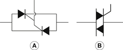
Figure 29.1 Simplified diagram of primary switching using (A) two silicon-controlled rectifiers and (B) a triac.
During the exposure, the timer is simply required to apply a sequence of synchronized pulses to the gate of the device at a time slightly later than the mains zero to switch them back on and ensure their continued conduction. At the end of the exposure, these pulses stop and conduction through the device stops at the end of the next half-cycle. The system allows accuracy of one voltage pulse (i.e. an exposure time of 0.01 second in the case of a two-pulse unit, or 0.002 seconds in the case of a medium-frequency unit; see Ch. 28).
29.3.2 Secondary switching
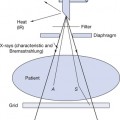
As will be seen in Chapter 30, X-rays are produced when electrons flow from the cathode to the anode of the X-ray tube. These electrons are normally focused onto the target of the tube by a focusing cup, which is at a negative potential approximately equal to that of the filament. If a separate additional negative bias is applied to the focusing cup, then it is possible to make it more negative than the filament. X-ray tubes offering this facility are known as grid-controlled tubes.

Stay updated, free articles. Join our Telegram channel

Full access? Get Clinical Tree


