Midfacial Trauma
- Ken F. Linnau
Indications and Rationale for Repair
The overt physical manifestation of facial trauma often causes acute psychologic distress and long-term psychologic sequelae in addition to the loss of facial organ function. The use of modern surgical repair procedures, including internal reduction, microplate fixation, and the use of bone and allograft material has led patients to expect near normal if not normal appearance and function following the repair of midfacial injuries. The maxillofacial surgeon strives to restore both the physiologic function of the face and the anatomic form of an individual to resemble as closely as possible the appearance of the patient before the insult. Swelling of the facial soft tissues usually limits reliable clinical evaluation of the injuries and precludes immediate repair in the acute posttrauma period. Associated injuries such as cranial or facial hemorrhage, head injury, cervical spine injury, or major trauma to other body regions may require more immediate attention and treatment before midfacial injury repair. Most surgeons believe that the optimal time for internal fixation of midfacial injuries is approximately 7 to 10 days after the injury, when the initial swelling has subsided but before early fibrous tissue formation and tissue contraction. Anatomically correct realignment of displaced fracture fragments is most easily achieved before early bone healing occurs. To avoid refracture or osteotomy for movement and subsequent fixation of displaced facial skeletal segments, it is important that surgical procedures are performed in a timely fashion. The final configuration of the facial soft tissues will depend on the anatomic position of the underlying facial skeleton, and only then will soft tissue healing occur in the normal configuration. Incompletely reduced facial fractures may result in cicatricial contracture with permanent thickening, shortening, and displacement of the facial soft tissue structures, potentially requiring multiple reoperations. Delayed or secondary repair of both bone and soft tissue defects is more challenging with less favorable results compared to primary reconstruction. Reoperation through scar tissue that has resulted from previous surgical procedures increases the risk for iatrogenic complication such as lid retraction or ectropion ( Table 5-1 ). Early comprehensive surgical repair is therefore advocated, which requires high-resolution high-quality imaging to supplement clinical examination and allow for precise operative planning.
| Deformity | Description |
|---|---|
| Enophthalmos, exophthalmos | Abnormal globe position due to abnormal orbital volume post injury |
| Saddle nose | Nasal deformity due to ischemic septal necrosis from unrecognized nasal septum hematoma |
| Telecanthus | Malposition of the medial canthal ligament with lateral displacement and rounding of the inner canthus |
| Shortened midface | Upward “telescoping” of the maxilla on itself can be caused by exaggerated reduction of Le Fort I or II injuries |
| “Dish face” deformity | Flattened and widened midface due to posterior and lateral displacement of the paired midfacial components (especially zygoma) |
| “Facies equina” deformity | Elongated face due to downward displacement of the palatoalveolar complex and forward rotation of the mandible |
The Buttress System of the Face
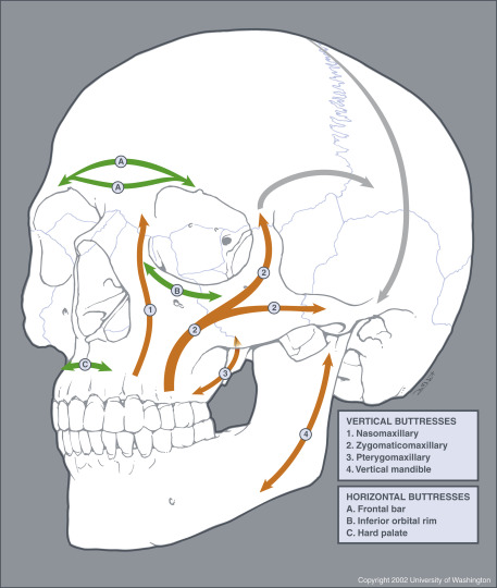
The facial anatomy is very complex and at times overwhelming. It is therefore useful to categorize facial injury by distinct facial region, including the nose, the orbit, the maxilla, the mandible, and the zygoma. From the surgical perspective, the soft tissues of the face, including the dermis, connective tissues, and muscles, are layered over a deep supporting latticelike system of bony buttresses ( Fig. 5-1 ). The integrity of this honeycomb-like bony grid is instrumental for satisfactory aesthetic results after midfacial microplate surgery. Using the buttress concept in evaluating facial injury can therefore facilitate fracture description and conceptualization and aid in preopera tive decision making. The strongest midfacial buttresses (see Fig. 5-1 ) are vertically oriented in response to physiologic loads on the system exerted by similarly directed masticatory forces. Weaker horizontally and sagittally oriented buttresses reinforce the system. The buttress system is therefore less resistant to external direct impact from the front or side, which may lead to traumatic disruption of one buttress and weakening of the entire lattice with subsequent collapse. This collapse, however, is not altogether a random process but occurs in characteristic fracture patterns ( Fig. 5-2 ). Familiarity with the major buttresses of the face allows the radiologist to more easily detect facial injury and conduct a structured step-by-step image evaluation without overlooking subtle facial injury.
Imaging Technique
Imaging evaluation of maxillofacial injury aims to depict the location and displacement of facial fractures and to define soft tissue injury that potentially compromises respiration, vision, mastication, and lacrimal system function. Today multidetector computed tomography (MDCT) has become the imaging modality of choice for evaluation of apparent or suspected facial injuries, nearly completely replacing facial radiography. Particularly in the polytrauma setting, rapid submillimeter MDCT image acquisition has proven to be very efficient owing to highly accurate isotropic pixel resolution of thin-collimation computed tomographic (CT) images that allow real-time multiplanar reformations (MPRs) without moving the patient. To facilitate injury depiction and aid operative planning, three-dimensional (3-D) image reconstruction is frequently used at major trauma centers. Some surgeons advocate intraoperative CT scanning to monitor the repair.
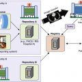
At Harborview Medical Center, trauma patients with obvious or suspected facial injuries undergo helical scanning of the entire skull extending from the vertex to the mandibular angle. Using the same data set, head CT images for intracranial and brain evaluations and maxillofacial CT images are reconstructed. Asymmetric patient positioning in the scanner gantry, which is not uncommon in severely injured polytrauma patients, is retrospectively corrected by aligning image reconstruction with the standard craniometric reference planes (Frankfurt horizontal plane, also referred to as the orbitomeatal plane , auriculoinfraorbital plane, or eye-ear plane ) used for surgical planning and repair of facial fractures. For facial evaluation, 0.6-mm-thick slices in the axial, sagittal, and coronal plane are routinely generated in bone and soft tissue algorithm. If midfacial injury is detected, the same data set is used to subsequently create shaded-surface-3-D rendered images of the facial skeleton to aid surgical planning. In the setting of orbital injury, sagittal reformations are aligned along the optic nerve. Although not part of the midfacial skeleton, the vertically oriented portion of the mandible (ramus) functions as the most posterior vertical buttress of the facial skeleton and comes into play in severely comminuted midfacial fracture repair. It is therefore essential for surgical planning to include the entire mandible in the initial facial CT evaluation.
Patterns of Injury
Facial fractures can involve multiple regions or bones of the face, and it is often difficult to classify facial fractures on the basis of the bones involved alone. Facial fractures can at times be overwhelming but may be categorized by classic fracture patterns, including, nasal, naso-orbitoethmoid (NOE), zygomaticomaxillary complex (ZMC), orbital, and maxillary Le Fort fractures. The role of the emergency radiologist is to recognize these fracture patterns, summarize the injuries detected, and alert clinical providers of unexpected findings and potential complications.
Nasal Bone and Naso-orbitoethmoid Fractures
Nasal fractures are very common owing to the prominence of the nasal dorsum and the relatively weak bony support. Young men in their second and third decades are most commonly affected. Potential sequelae of nasal fracture include airway obstruction, cosmetic deformity, and cerebrospinal fluid leak. Hematoma in the nasal septum may lead to necrosis of its cartilaginous portion with ensuing saddle nose deformity. An associated anterior maxillary spine fracture can be the hallmark to indicate disruption of the cartilaginous portion of the nasal septum.
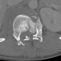
Naso-orbitoethmoid complex injuries occur during high-energy impactions when the nasal bones, which are more resistant to frontal impact, fail and expose the delicate ethmoid air cells behind them ( Fig. 5-3 ). The nasal bones then telescope into the deep face, involving the medial orbital wall. An increased intercanthal distance (telecanthus) and flattening of the nasal dorsum or disruption of the medial canthal ligament insertion (positive eyelid traction test) should raise suspicion for NOE fracture. Naso-orbitoethmoid fractures are clinically classified according to integrity of the central fragment, where the medial canthal ligament inserts.

Zygomaticomaxillary Complex Fractures
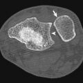
The zygoma forms the cornerstone of the facial frame, and its strong bone defines the projection or depth of the malar eminence of the cheek. The zygoma is related to the surrounding craniofacial skeleton through two critical arcs of the external facial contour. First, the horizontal external arc curves from the lacrimal fossa along the inferior orbital rim over the malar eminence to the zygomatic arch. Second, the vertical arc also crosses over the malar eminence and defines the course of the lateral facial buttress from the maxilla to the lateral frontal bone. The zygoma thus becomes a central part of the zygomaticomaxillary (lateral) vertical buttress of the face (see Fig. 5-1 ). Sutural attachments of the zygoma include the frontal bone (zygomaticofrontal suture), the maxilla (zygomaticomaxillary suture), the arch of the temporal bone (zygomaticotemporal suture), and the greater wing of the sphenoid (zygomaticosphenoid suture), which should not be mistaken for fractures. Because the zygoma forms a portion of the lateral orbital wall and lateral orbital floor, orbital fractures are frequent components of ZMC injuries ( Fig. 5-4 ). In addition, fractures may cross the infraorbital canal, injuring the infraorbital nerve with subsequent cheek paresthesia. Postoperative spatial location of the zygoma will play a major role in reconstruction to reestablish correct facial height as well as width and projection (depth) of the face at this level. Careful anatomic realignment of all portions of the articulation of the zygoma to the surrounding craniofacial skeleton and stabilization of the zygoma in this position are mandatory for satisfactory aesthetic surgical repair.

Orbital Fractures
The orbit is a complex, conically shaped compartment composed of multiple bones contained within the buttress system of the midface. In practice the orbit consists of the medial orbital wall, the orbital floor, the lateral orbital wall, and the orbital roof ( Fig. 5-5 ). Collapse of the walls puts the orbital soft tissue organs at risk for injury. Fortunately, the thick superior orbital rim of the frontal bone and the strong lateral and inferior orbital rim of the zygoma enclose the orbital aperture in a ringlike fashion, protecting areas of relative weakness in the middle portion of the orbit (i.e., the very thin medial wall and orbital floor). The posterior orbital third is again composed of relatively thick bone that protects the vital soft tissue structures at the orbital apex (optic nerve, ophthalmic artery, carotid siphon, cavernous sinus). The orbital roof, floor, and medial wall are concave relative to each other, producing the greatest diameter of the orbit approximately 15 mm posterior to the inferior orbital rim. The globe is situated at this level of the orbital floor, which then inclines upward and inwardly in a convex curve behind the eyeball (see Fig. 5-3 , D and Fig. 5-5 ) to create a relative retrobulbar constriction to maintain the position of the retrobulbar soft tissues. Reconstruction of the orbital walls can begin only after the vertical and horizontal buttresses and thus the outer ring of the orbit have been restored and stabilized. This ring then serves as an anchor point for bone grafts or alloplastic implants that may replace the fragmented bone in the middle third of the orbit. Re-creation of the upward convexity of the normal orbital roof, the concave anterior orbital floor, the convex posterior floor, and the obtuse angle of the transition of the floor to the medial orbital wall (lamina papyracea) are surgically challenging (see Figs. 5-4 and 5-5 ), commonly leading to undercorrection or overcorrection with altered orbital volume. Orbital volume changes exceeding 1.5 mL (approximately 5% of the normal orbital volume) may lead to an asymmetry in globe position that is aesthetically noticeable (enophthalmos or less commonly exophthalmos). With CT the convexity of the orbital floor is best appreciated on sagittal reformations, whereas coronal reconstructions allow accurate evaluation of the thin orbital floor and medial orbital wall integrity. Because the orbital axis is oblique, reconstructions parallel to the optic nerve are optimal. Orbital trauma may be isolated, such as a blow-out fracture, or more commonly, associated with complex midfacial fracture patterns, including NOE, ZMC, and Le Fort fractures ( Figs. 5-6 and 5-7 ; see Fig. 5-4 ).


Mandible Fractures
Midfacial fracture repair often begins with the placement of arch bars and maxillomandibular fixation (MMF) wires to maintain accurate interdigitation of the maxillary and mandibular teeth. If the strong bone of the horseshoe-shaped mandible remains entirely intact or is accurately reconstructed from condyle to condyle, the desired functional relationship between the bite plane (that is the imaginary surface anatomically relating the cranium to the occluding surfaces of the teeth) and the skull base is accomplished (see Fig. 5-1 ). In this way the mandible can serve as a platform for maxillary reconstruction, particularly in the setting of highly comminuted Le Fort fractures (see Fig. 5-7 , E ). The intact mandibular ramus buttress in anatomic position thereby guarantees correct posterior vertical dimension because the posterior midfacial buttress, composed of the plates of the pterygoid process, is not accessible to surgical repair. Similarly, anatomic position of the body and angle of the mandible guarantee the width of the lower aspect of the midface to avoid an overly rounded postoperative frontal facial appearance. Mandibular integrity is of particular importance if a displaced sagittal split fracture of the hard palate alters the maxillary width.
Frontal Bone Fractures
The frontal bone is composed of a strong osseous ridge, which forms the upper margin of the face and owing to its strength is often referred to as the frontal bar . It is able to sustain large forces before fracturing. If this strong osseous ridge is uninjured or adequately restored, the maxillofacial surgeon may use it as a starting point for midfacial reconstruction. Deep to the most superficial cortex of the frontal bone lies the frontal sinus, which is bound by anterior and posterior bony walls commonly referred to as anterior and posterior tables . The posterior table separates the sinus from the anterior cranial fossa. When both tables of the frontal sinus are fractured in the setting of facial injury, a compound (open) skull fracture involving the central nervous system (CNS) results (see Fig. 5-7 ) and requires at the minimum antibiotic treatment to prevent CNS complications such as meningitis, encephalitis, brain abscess, and cavernous sinus thrombosis. A key finding to detect involvement of the posterior table is pneumocephalus, which can be subtle and should be actively sought by the radiologist (see Fig. 5-3 , E ). Posterior propagation of frontal bone fractures may manifest as CNS rhinorrhea.
Maxilla and Le Fort Fractures
Centrally in the middle of the face lies the paired maxilla, housing the upper teeth and contributing to the walls of the nasal cavity, oral cavity, and orbit. The maxilla is part to three vertically oriented facial buttresses, which developed as a response to the forces of the masticatory muscles (see Figs. 5-1 and 5-4 ). Most medially lies the nasomaxillary (nasofrontal) buttress connecting to the medial frontal bone at the level of the glabella. The bifurcated zygomaticomaxillary buttress lies more laterally and extends from the alveolar process over the malar eminence of the zygoma to the zygomatic process of the frontal bone at the level of the lateral orbital rim. The posterior (pterygomaxillary) vertical buttress of the midface, which is surgically not accessible, extends from the posterior wall of the maxillary sinus (maxillary tuberosity) to the medial and lateral plates of the pterygoid process of the sphenoid bone. The inferior orbital rim, zygomatic arch, and palatoalveolar complex provide secondary horizontal buttress support.
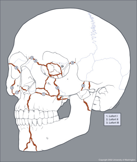
The three classic fracture patterns of the maxilla were originally described by Le Fort based on his exemplary cadaver studies. The common feature of Le Fort maxillary fractures is the involvement of the pterygoid plates of the sphenoid bones, resulting in separation of the midface from the skull base. In clinical practice, midfacial fractures tend to be asymmetric, and each side can be described as a separate hemi–Le Fort fracture to facilitate communication among providers (see Figs. 5-2 and 5-7 ).
The Le Fort I fracture pattern involves the maxilla and nasal septum at the level of the inferior aspect of the piriform aperture, thereby creating a free-floating hard palate and alveolar process, which are separated from the remainder of the midface (see Fig. 5-6 ). The Le Fort II, or pyramidal, fracture pattern separates the nasal region from the cranium by extension through the nasal bridge and inferior orbital rim. The zygomatic bone remains attached to the skull base in pyramidal fractures (see Fig. 5-7 ). The Le Fort III fracture pattern causes complete craniofacial disjunction through fracture through the nasofrontal suture, lateral orbital rim, and zygomatic arch (see Fig. 5-7 ). All Le Fort fracture patterns include posterior fracture of the pterygoid process.
Reconstruction of the midfacial buttress system begins with stabilization of the frontal bar, to which the more gracile displaced midfacial structures are then suspended. Through stepwise top-to-bottom reconstruction of the buttresses, the vertical dimension of the midface is restored with careful attention to avoid overreduction, which can result in telescoping and shortening of the midface. Given the high incidence of concurrent facial fractures such as NOE or frontal bone injury, surgical repair of these injuries is usually complex. Of particular concern are concomitant fractures of the hard palate, dentoalveolar units, and posterior fracture extension toward the orbital apex and optic nerve.
Complex Facial Fractures
Panfacial fractures or facial smash injuries (see Fig. 5-7 ) are sustained during high-energy trauma with simultaneous injury of multiple regions of the face, often as part of accompanied multisystem trauma. For these injuries no universally accepted calcification system exists. Sequelae of maxillofacial reconstruction are common in these patients (see Table 5-1 ). To integrate treatment plans and better evaluate patient outcomes, a comprehensive facial fracture severity scoring system, which is not specific to a particular facial region, has been proposed for panfacial injury.
Traumatic Craniocervical Vascular Injuries
- Clint W. Sliker
Neither blunt nor penetrating traumatic craniocervical arterial injuries are common, but both are very significant groups of injuries encountered in the practice of trauma and emergency radiology because both are associated with high mortality. Penetrating neck trauma is associated with a mortality ranging from 2% to 10% with most early death resulting either directly or indirectly from arterial injury that leads to exsanguination, airway compromise, or stroke. Mortality is high in patients with blunt arterial injuries (BAIs) as well, ranging from 8% to 38%. Although mortality in patients with BAIs frequently can be attributed to other severe coexisting injuries; injury-specific mortality secondary to stroke is common. The key to reducing morbidity and mortality in patients with both penetrating arterial injuries (PAIs) and BAIs is rapid diagnosis and treatment.
As with most vascular disease, craniocervical arterial injuries can be diagnosed with a number of different imaging modalities, including digital subtraction angiography (DSA), magnetic resonance angiography, duplex Doppler sonography, and multidetector computed tomographic angiography (CTA). Each diagnostic option has its own particular merits and limitations. However, of the group, CTA has the greatest overall practical utility when evaluating the acutely injured patient in that it is noninvasive, quick, readily available in most contemporary emergency departments (EDs), and easily integrated into established diagnostic algorithms. In addition, multidetector CTA has been shown to be a useful tool that can have a positive clinical impact when used to evaluate patients for either penetrating or blunt craniocervical arterial injuries.
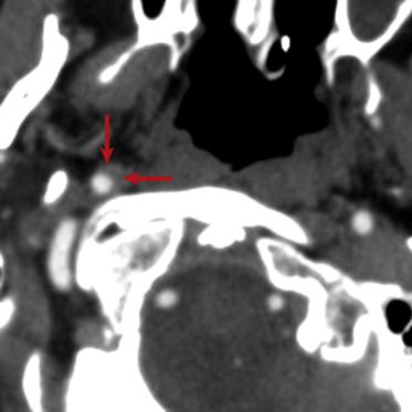
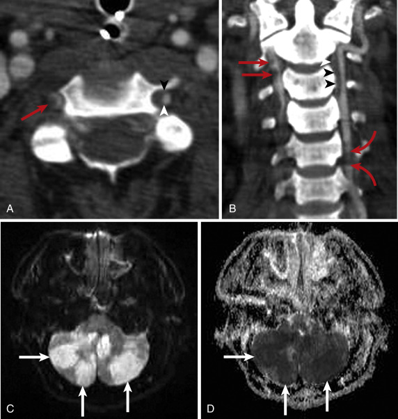
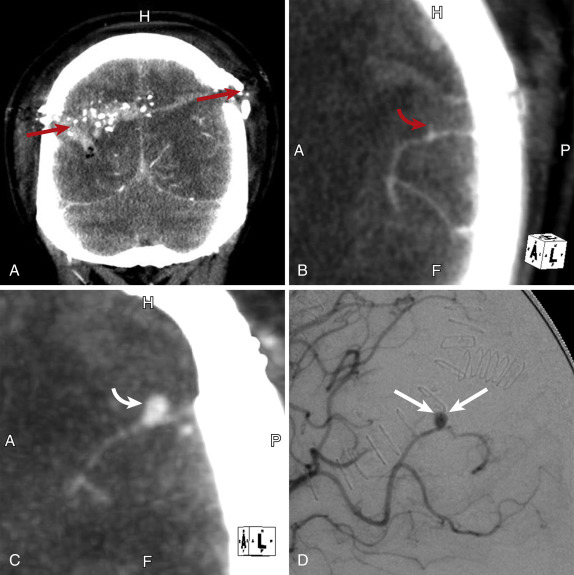
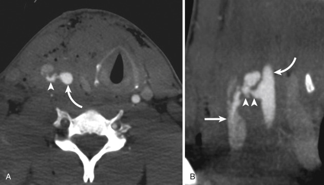
Craniocervical arterial injuries are varied in morphologic and physiologic manifestations. Manifestations of injury include minimal intimal injury (i.e., intimal irregularity), intramural hematoma ( Figs. 5-8 and 5-9 ), raised intimal flap (see Fig. 5-9 ), pseudoaneurysm ( Fig. 5-10 ), intraluminal thrombus, occlusion ( Fig. 5-11 ; see Fig. 5-9 ), complete or partial transection with active hemorrhage ( Fig. 5-12 ), and arteriovenous fistula (AVF) ( Fig. 5-13 ). Both blunt and penetrating mechanisms can result in any of the various types of injury, although, in my experience, active hemorrhage tends to be more frequently encountered in patients with PAI.
Blunt Cervical Arterial Injuries
Blunt injury may occur anywhere along the length of the carotid and vertebrobasilar arterial systems, but clinically significant injuries tend to occur in the cervical segments of the internal carotid and vertebral arteries. Vascular injury may occur as the consequence of a direct blow to the vessel. However, the main cause of blunt injury is thought to be stretching of the artery to the point of mechanical failure. The predominant mechanism is thought to be hyperextension and contralateral rotation of the head, which stretches the internal carotid artery over the transverse processes of C1 and C2, or cervical spine subluxation/dislocation that stretches the vertebral artery over fixed spinal structures. Arteries may also be stretched by craniocervical distraction or crushed between bone fragments at sites of craniofacial or cervical spine fracture. Reflecting the complex mechanisms of injury experienced by many multitrauma patients, multivessel injuries (i.e., more than one carotid and/or vertebral artery segment injured) are common and diagnosed in 18% to 38% of patients with BAI (see Fig. 5-9 ).
Clinical signs of BAI include active arterial hemorrhage from an open wound, mouth, nose, or ears; an expanding neck hematoma, cervical bruit, especially in patients younger than 50 years; pulsatile tinnitus; pulsatile exophthalmos; Horner syndrome or oculosympathetic paresis; fixed neurologic deficits, either lateralizing or central, that are incongruent with the findings of neurologic imaging; transient ischemic attack; and neuroimaging findings of cerebral infarction that are unexplained by hypotension, intracranial herniation, or anoxia. Many patients come to the ED with clinical signs of injury. However, in 56% to 86% of patients, BAI typically does not manifest until after a clinically silent interval that usually lasts several hours but may last several months.
In both symptomatic patients and asymptomatic patients with BAI, treatment improves patient outcome. Twenty-six percent to 57% of patients with untreated BAI may experience BAI-specific stroke (see Fig. 5-9 ), whereas only 0% to 4% of patients in whom injury is treated suffer stroke, resulting in decreased injury-specific mortality. Although both surgical repair and endovascular intervention have roles in the treatment of BAI in select patients, the current mainstays of treatment are anticoagulation and antiplatelet therapy, either alone or in combination.
Injury Grading
Based on the various imaging manifestations of injury, Biffl and colleagues devised a BAI injury scale for blunt carotid artery injuries that they later applied to blunt vertebral artery injuries. In the Biffl blunt arterial injury scale (also known as the Denver scale), grade I injuries include those with minimal intimal irregularity or intramural hematoma (see Fig. 5-8 ) causing less than 25% luminal stenosis. Grade II injuries (see Fig. 5-9 ) exhibit a raised intimal flap, an intraluminal thrombus, or an intramural hematoma causing 25% or more luminal compromise. Grade III injuries are pseudoaneurysms. Grade IV injuries (see Fig. 5-9 ) are arterial occlusions. Grade V injuries (see Fig. 5-12 ) are arterial transections with active hemorrhage or hemodynamically significant AVFs. The highest possible grade is attributed to each injury, and in patients with more than one BAI, each is graded separately. Although initially devised to characterize injuries diagnosed with DSA, the Biffl grading system can be readily applied to BAI diagnosed with multidetector CTA. In addition to providing prognostic information, injury grading is a practical means of simplifying injury characterization and communication within the context of the varied imaging appearances of BAI. Moreover, though the efficacy of several currently accepted therapeutic options relative to others remains unsettled, some institutions, such as mine, tailor therapy based on injury grade.
Blunt arterial injury grading has particular value in the instance of blunt carotid artery injuries because Biffl and coworkers demonstrated a general linear relationship in the grade of blunt carotid injury and frequency of injury-related strokes: 3%, 11%, 33%, 44%, and 100% with injury grades I, II, III, IV, and V, respectively. The relationship between grade of blunt vertebral artery injury and frequency of stroke is nonlinear, with higher rates of stroke associated with injury grades II (40%) and IV (33%) (see Fig. 5-9 ), whereas grades I and III are associated with stroke in 19% and 13% of patients, respectively. Mortality rates are generally proportionate to the stroke rates for each injury grade. Note that Biffl and coworkers did not publish data for grade V blunt vertebral artery injuries, although I have diagnosed three grade V vertebral artery injuries in my practice, all of which were the likely cause of patient mortality. Blunt arterial injuries are not static lesions and may either regress or progress in grade over the course of as little as 1 week, leading to changes in management, which highlights the need for routine imaging follow-up at 7 to 10 days.
Multidetector Computed Tomographic Angiography—Accuracy and Clinical Utility
Initially multidetector CTA showed promise as a means to accurately diagnose BAI, relative to the accepted reference standard, DSA, with 16-channel CTA having a reported sensitivity of 98%. However, subsequent studies provided less favorable results with sensitivities ranging from 29% to 64%, which were not improved with advancing 32- and 64-channel technology. Clearly, multidetector CTA cannot be considered to be diagnostically equivalent to DSA when used to diagnosis BAI.
Despite its diagnostic limitations in regard to accuracy, multidetector CTA is still a valuable tool when used to evaluate patients for BAI. Not only does CTA have practical advantages over other diagnostic options, including DSA, but it has also been shown to be a more cost-effective tool when used as the primary means to diagnose BAI. The cost-effectiveness relative to DSA, MRA, and sonography can be realized whether patients are acutely symptomatic or asymptomatic.
For clinical utility, multidetector CTA is probably most useful when used to diagnose BAI in the context of screening. Recall that treatment of BAI while asymptomatic improves patient outcomes. From 56% to 86% of patients with BAI do not exhibit symptoms from hours to months after injury is sustained. Early identification of asymptomatic BAI may alter the initial treatment plan in up to 68% of patients. It has been reported repeatedly that screening select groups of blunt trauma patients for BAI allows diagnosis and treatment of patients before onset of symptoms, usually related to ischemia, and improves patient outcomes. Adoption of a structured BAI screening program based on the use of multidetector CTA can significantly increase the frequency of BAI diagnosed at a given institution. More important clinically, BAI-specific stroke and mortality rates are significantly lower in screened populations relative to unscreened populations. Though screening with DSA may also yield clinically significant improvement in BAI-specific mortality, primary use of CTA rather than DSA still results in improved patient outcomes with fewer injury-specific strokes, presumably because of more-rapid access to CTA.
To achieve the benefits of any screening program, there must be a high-risk patient population to target for screening. A number of specific injury patterns or clinical findings have been reported as risk factors for BAI and therefore indications to screen for arterial injury. In general, they suggest that the patient was subjected to those injury mechanisms that may cause BAI, and they are readily identified early in patients’ clinical course. Among the more widely reported risk factors are Glasgow Coma Scale score less than 6, diffuse axonal injury, skull base fractures involving the central skull base or carotid canal, Le Fort II or Le Fort III facial fractures, major thoracic injuries (Abbreviated Injury Scale score greater than 3), and cervical spine injury manifesting as fracture or subluxation. Blunt arterial injury may be diagnosed in nearly two thirds of patients with established “high-risk” criteria, yet up to 20% of asymptomatic BAI will go still go undiagnosed. To identify more of those “missed” BAIs, complex skull fractures, scalp degloving injury, and mandible fractures can also trigger screening. As a practical matter, clinical judgment and recognition of injury mechanism, rather than a specific injury or clinical sign, are of paramount importance in identifying patients who may harbor BAI. Accordingly, irrespective of specific screening criteria, all patients who may have been subjected to hyperextension in the craniocervical region, especially with rotation, distraction, or crush/direct impact, should have multidetector CTA of the head and neck to evaluate for BAI.
Penetrating Neck Trauma
The neck is an anatomically complex region with multiple vital structures located in a small region. When penetrating trauma to the neck violates the platysma, multiple structures that require early treatment can be injured, including the vascular system, aerodigestive tract, and spine. Arterial injuries occur in 15% to 25% of patients with penetrating neck trauma, whereas laryngotracheal and esophageal injuries occur in 1% to 7% and 0.9% to 6.6%, respectively.
Consequently, despite the extreme clinical importance of the major neck arteries, the diagnostic evaluation of neck-penetrating arterial injuries can only be approached in the context of the neck as a whole.
Although any penetrating object may violate multiple tissue planes and anatomic compartments, the extent of damage from penetrating trauma depends greatly upon the nature of the projectile or sharp object. Low-energy trauma, such as a knife stab wound or nail-gun injury, is generally associated with less extensive injuries resulting from direct impact against a given anatomic structure. With high-energy penetrating trauma, such as a gunshot wound from a shotgun or high-velocity hunting rifle, injuries result from direct impact, as well as tissue cavitation resulting from a shock wave and/or secondary missile formation (e.g., bone fragments). The situation can be further complicated when there are multiple, comingled penetrating wound tracks.
Surgically accessible PAIs are frequently treated with surgical repair, which also affords the opportunity to inspect, and potentially repair, other vital structures in the region of the wound track. Some difficult-to-access or surgically-inaccessible PAIs can be addressed with endovascular treatment.
Diagnosis and Treatment—Influence of Clinical Examination and Anatomy
Clinical decisions regarding the appropriate initial steps taken in both diagnosis and treatment of patients with penetrating trauma violating the platysma are based upon the clinical examination findings of any “hard” or “soft” signs of clinically significant penetrating neck injuries. Hard clinical signs—those strongly suggestive of a significant injury—include brisk, active bleeding from the wound; an expanding or pulsatile neck hematoma; cervical bruit or thrill (especially in a young patient); massive hemoptysis or hematemesis; shock refractory to intravenous fluids; and air bubbling from the wound. Soft clinical signs—those weakly suggestive of a significant injury—include venous oozing from the wound, nonexpanding and nonpulsatile neck hematoma, minor hemoptysis, dysphonia, dysphagia, and subcutaneous emphysema. Those presenting with hard signs of injury typically undergo immediate surgery to promptly diagnose and repair potentially fatal vascular or aerodigestive injuries. Patients with soft signs of penetrating neck injury generally can be evaluated with less invasive means, including diagnostic imaging and endoscopy. Most patients without any clinical signs of significant penetrating injury can usually be safely observed for 24 hours to look for delayed manifestations of injury, though 23% to 30% may harbor clinically significant, albeit acutely asymptomatic injuries, thereby suggesting that this population should be considered for diagnostic testing.
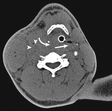
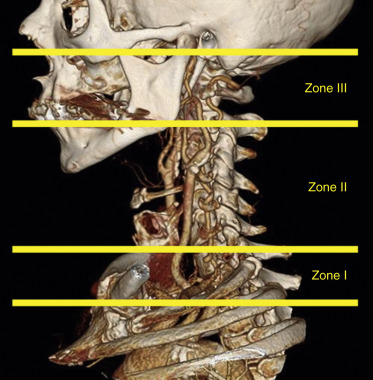
Management of penetrating neck injuries is also guided by the site of the entry wound based on the zonal anatomy of the neck. In the setting of penetrating neck trauma, the neck is divided into three zones ( Fig. 5-14 ). Overlapping inferiorly with the thoracic inlet, zone I extends from the sternal notch and clavicles to the level of the cricoid cartilage superiorly. Zone II includes the region between the cricoid and the level of the mandibular angles. Finally, zone III extends from the mandibular angles to the skull base. To the surgeon, localization of the anatomic zone of injury is important because it may influence the approach he or she uses to treat any clinically significant injury. For example, many zone II injuries are accessible to the surgeon via an approach from the neck. In contrast, given the overlap with the thoracic inlet, zone I injuries frequently require combined thoracic and cervical approaches. Surgical access to zone III injuries may be either difficult or impossible due to facial structures and proximity to the skull base. Accessible injuries usually undergo direct surgical repair, though in very select patients, nonoperative management may be initially attempted. In regard to surgically inaccessible injuries, especially vascular, imaging-guided repair is frequently employed.
Multidetector Computed Tomographic Angiography—Accuracy and Clinical Utility
A number of studies report the accuracy of CTA for detecting clinically significant penetrating neck injuries. Because of the complexity of neck-penetrating trauma, the reference standards to which CTA was compared typically comprised the aggregate results of surgical exploration, DSA, esophagography, endoscopy, and clinical observation. Overall, results for CTA are excellent, regardless of the number of detectors, with sensitivities and specificities of 90% to 100% and 93.5% to 100%, respectively. Reflecting my clinical experience, reported false-positive results typically involved potential aerodigestive injuries.
The high accuracy of CTA for identifying significant injuries can greatly streamline the diagnostic evaluation of patients with penetrating neck injury. Importantly, in patients without indications for immediate surgery, reports in the medical literature suggest that negative neck exploration rates can be significantly reduced, albeit not eliminated entirely, when CTA is used to guide management decisions rather than the combination of clinical findings and anatomic zone of the entry wound. In regard to specific diagnostic tests, the use of CTA significantly reduces the need for DSA in this population. It is less clear if the use of CTA also leads to a significant reduction in the need for either esophagography or endoscopy, but the trend suggests that it does, which is supported by my experience. Finally, cervical spine fractures are common in patients with penetrating neck trauma, and CT is an integral part of evaluating cervical spine and facial fractures. Therefore, when CT scan protocols are constructed to account for and clearly display bony structures, as well as vascular and aerodigestive structures, multidetector neck CTA can be better used as a comprehensive diagnostic tool.
The key to both maximizing the diagnostic accuracy of CTA and realizing its full clinical utility when evaluating patients with penetrating neck trauma is the identification of the wound track (or tracks). Imaging manifestations of the track include gas, hemorrhage/edema (i.e., fat stranding), ill-defined fluid or hematoma, and either primary or secondary missile fragments, especially when caused by a thin, sharp object, such as a stiletto, or small caliber firearm. Imaging manifestations of the wound tract may be very subtle. Because it is common for wound tracks to extend through multiple anatomic zones and compartments, a thorough search for the signs of the track must be mounted both in close proximity to and remote from the entry wound. Viewing with an independent workstation allows for oblique multiplanar reconstructions, facilitates track identification.
Delineating the wound track can lead one to identify all vital structures that are injured or potentially injured by the penetrating object (see Figs. 5-10 and 5-11 ). Conversely, identification of the track may help one exclude injury to those structures spatially removed from the wound track. In most instances, when a specific injury is identified, the comprehensive examination provided by CTA allows definitive therapeutic plans to be made. Despite an otherwise normal appearance, when a vascular or aerodigestive structure is within the wound track, it is difficult to definitively exclude an injury to that structure. In those instances, further diagnostic testing or at times surgical exploration can be targeted to those areas at greatest risk for injury.
Intracranial Vascular Injuries
Multidetector Computed Tomographic Angiography—Accuracy
The accuracy of CTA for specifically detecting intracranial arterial injuries has not yet been fully explored in the medical literature, and data are very limited. When used to diagnose cerebral aneurysms in patients with posttraumatic subarachnoid hemorrhage (SAH), multidetector CTA has reported sensitivities and specificities of 95% to 97.6% and 95.1% to 96.2%, respectively. However, because of the varying morphologic manifestations of BAI, it is uncertain if comparable accuracies can be achieved when CTA is used to evaluate for BAI. Still, given its practical advantages, multidetector CTA is a desirable first-line diagnostic option.
Arterial Injuries
Intracranial arterial injuries are much less common than cervical arterial injuries, but they remain a clinically significant group of injuries. Like cervical arterial injuries, they may lead to thromboembolic stroke. However, they pose a greater risk for hemorrhagic complications, especially from pseudoaneurysms, leading to hematoma that causes mass effect and subsequent cerebral injury. When an arteriovenous malformation (AVM) occurs, neurologic complications may result from either vascular steal–associated ischemia or intracranial hemorrhage.
Blunt Arterial Injuries
Like cervical BAIs, intracranial BAIs tend to be associated with other injuries that result in either traction on the artery or impaction by a fracture fragment. In my experience, cavernous internal carotid segment injuries are more common and occur when fractures extend through the central skull base into the cavernous-sphenoid complex. Supraclinoid internal carotid artery or middle cerebral artery M1 segment injuries may occur as a consequence of acceleration-deceleration, a mechanism shared by diffuse axonal injury, which causes traction to be exerted upon the relatively fixed artery by the more mobile brain. Finally, the vertebral and basilar arteries can be stretched when there is a craniocervical distraction injury (see Fig. 5-12 , B ), or, rarely, the basilar artery can be entrapped in a clivus fracture. In general, given comparable clinical manifestations and considerable overlap of risk factors for both intracranial and cervical injuries, multidetector CTA of patients with potential BAI should include both the brain and neck.
Penetrating Arterial Injuries
The true incidence of intracranial PAI is uncertain. Though generally considered uncommon, the frequency of intracranial PAI may be high in some subsets of patients. For example, a recent study of war-related penetrating head trauma revealed a prevalence of 34%. Like BAI, intracranial PAI may occur anywhere within the intracranial circulation, but PAIs are more frequently diagnosed in the peripheral cerebral artery branches than in central arteries. Peripheral intracranial PAIs tend to be pseudoaneurysms, although AVFs are also commonly encountered. Although some may spontaneously regress, PAIs tend to be dynamic lesions that will worsen (e.g., pseudoaneurysm enlargement) over time (see Fig. 5-10 ), thereby increasing the risk for infarction or hemorrhage. Arteriospasm is a frequent associated finding, usually in or near the wound track, which may hinder either diagnosis or treatment of the injury itself. Accessible peripheral lesions may be treated surgically, but endovascular repair or occlusion of both peripheral and central injuries is a therapeutic option in many instances.
Indications for CTA in patients with penetrating head trauma are not uniformly defined. However, reported indications for cerebrovascular imaging of patients with penetrating head injury include penetrating injury through the pterional or orbitofrontal region, arterial injury demonstrated at surgical exploration, transcranial Doppler ultrasound findings of arteriospasm, and a spontaneous, unexplained decrease in either partial pressure of brain-tissue oxygenation or cerebral blood flow. In addition, given that arteriospasm may obscure an injury and that subtle injuries may increase in conspicuity over time, an initially CTA with negative findings should be followed with a repeat scan in 7 to 10 days.
Carotid-Cavernous Fistulas
A carotid-cavernous fistula (CCF), a subtype of AVF that results from abnormal direct communication between the internal carotid artery and cavernous sinus, is among the more common AVFs encountered in clinical practice. In penetrating trauma the fistulous communication occurs where the wound track crosses through the cavernous sinus into the cavernous segment of the internal carotid artery. Carotid-cavernous fistula secondary to blunt trauma likely occurs when shear stresses are transmitted through the connective tissue fibers within the cavernous sinus to the wall of the relatively fixed internal carotid artery, which occurs most frequently when a central skull base fracture extends into the cavernous sinus region. Complications of CCF include blindness or neurodeficits caused by either steal-induced ischemic infarction or venous hemorrhagic infarction. Posttraumatic CCFs are high-flow fistulas and rarely heal spontaneously. The longer the fistula goes without repair, the greater the chance of irreversible neurologic or ocular damage. Early treatment with endovascular techniques can improve clinical outcomes.
At times a CCF may be immediately apparent or may rapidly develop, although it usually takes several days for it to manifest clinically. Typical signs and symptoms include proptosis, chemosis, and orbital bruit, but it is not unusual for any one of these manifestations to be absent. It is important to consider that in severely injured multitrauma patients, especially those with severe craniofacial injuries, identifying signs and symptoms of CCF can be very challenging or impossible. Therefore a high level of suspicion is required by both the traumatologist and radiologist to ensure prompt diagnosis.
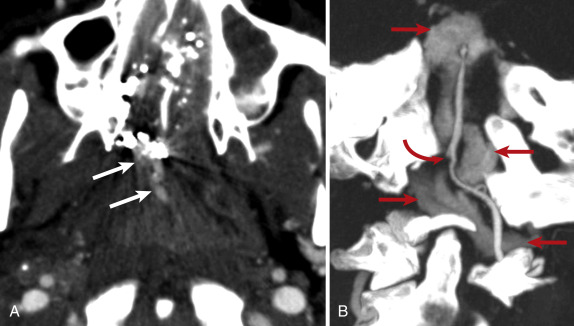
Computed tomography angiography signs of CCF ( Fig. 5-15 ) mirror the complex morphologic and physiologic changes that occur as a result of the injury. Though CCF is difficult to definitively identify, CTA can demonstrate a full-thickness defect within the cavernous internal carotid artery. Reflecting the abnormal arterialization of intracranial venous flow, the cavernous sinus may bulge laterally; the cavernous sinus may exhibit asymmetrically intense enhancement relative to the contralateral sinus; the sphenoparietal, inferior petrosal, and/or superior petrosal sinuses may be enlarged and exhibit asymmetrically increased enhancement; and cortical veins may be enlarged. Orbital abnormalities reflect abnormally increased venous outflow from the cavernous sinus and corresponding elevation in intraorbital pressure. The superior ophthalmic vein is typically abnormal, exhibiting asymmetric enlargement (diameter greater than 4 mm), early enhancement, and tortuosity. Other common orbital findings include proptosis and extraocular muscle enlargement (medial or lateral rectus muscle diameter greater than 4 mm). Typically, but not universally, severe injuries to the orbit are ipsilateral to the CCF abnormalities, although they may manifest in the contralateral sinus and orbit as well. As with the clinical signs of injury, these abnormalities may be very subtle or absent soon after injury, and a repeat CTA several days later may reveal them.