Chapter 18 Facial bones
The most frequent reason for radiological examination of the facial bones is trauma to the region; plain radiographic imaging of the area remains a popular and appropriate method of initial assessment in the acute setting, providing information relatively quickly and with a relatively low radiation dose compared to computed tomography (CT), the other imaging method best suited for providing information on bony injury to the area. Low-dose CT is considered a suitable method for demonstration and assessment of orbital fractures, as plain radiographic images can sometimes be inconclusive and may not give the 3D information needed before treatment of fractures. For many years it has been suggested that plain radiography may only be useful in cases showing clinical signs that clearly suggest surgical intervention,1 but current guidelines still show that plain radiography has a place in the assessment of facial and orbital injury.2 Magnetic resonance imaging (MRI) may also be considered, but as scans are undertaken supine, the teardrop effect of the herniating orbital tissue may not be as well demonstrated as in the prone CT scan with coronal sections. CT will provide better bony definition on the images.
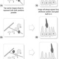
Injury to the nasal bones is not considered a reason for routine radiographic examination, but clinical specialists (e.g. for ear, nose and throat, and maxillofacial follow-up) may consider special nasal bones projections to be useful.2 This would be the case when assessing fragment displacement and septal deviation.
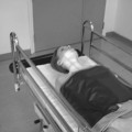
Similarly to requirements for imaging the cranium, the severely injured patient will present on a trolley and any occipitomental (OM) projections must be modified to a mento-occipital position, with angle direction opposite to that for OM. Laterals can be undertaken with the image receptor (IR) supported vertically at the side of the face. A description of a modified projection for zygomatic arches on the trolley-bound patient is also given. Facial examinations in the emergency situation are also covered in the A&E chapter of this book (Chapter 25).
The choice of projections for facial bones appears to vary according to referring clinical or individual hospital protocol, but rarely includes the lateral facial bones projection. It is common to find that at least two OM projections are used, with tube angle or no angle, and there have been studies in the past to investigate whether a single projection can be used;3,4 the most likely projection that can be suggested for this is referred to as the OM 30° in related articles, but it is necessary to ask whether this means that the orbitomeatal baseline (OMBL) lies at 30° to the IR and using a central ray perpendicular to the IR, or if a true OM with OMBL at 45° is used with a caudal tube angle of 30°. Fortunately, one article does include an image that shows the petrous ridge clearly level with the middle of the maxillary sinuses, indicating that the projection required an OMBL at 30° to the IR but with no tube angle.3 This position is familiar as the routine OM for orbits,5 which is collimated to include only the orbital outlines and maxillary sinuses for that area; clearly, if this projection is used for full facial bones assessment then all facial bones must be included in the primary beam. Investigation of the idea of one ‘ideal’ projection for facial bones assessment has involved consideration of articles and textbooks relating to radiographic positioning or recommendation of projections in facial trauma, and has yielded some additional interesting results that give rise to some very pertinent points when discussing imaging and referral.
All radiographers use eponymous terms for a few projections, for example Towne’s projection of the skull, Judet’s views of the acetabulum and Garth’s projection of the shoulder. Unfortunately, this makes the actual technique used less memorable than the name. In the last 30 years UK textbooks have aimed to use nomenclature that indicates the actual position for the projection, rather than the name of the projection’s designer, with addition of the eponymous title next to the descriptive title. Unfortunately this is not necessarily the case internationally, and eponymous titles are frequently used, leading to a varying range of projection names which are then incorporated into journal articles, potentially creating confusion or even misinterpretation. A search for a list of all eponymously named projections showed that there are approximately 200 in existence,6 although many are supplementary specialist projections that have been largely superseded by additional imaging modalities. Of this long list, only 17 appeared to be familiar in the UK.
An example of variation in nomenclature when discussing radiography of the facial bones can be centred around the OM projection and therefore has particular relevance to this chapter. In the UK OM tends to refer to a position with the OMBL at 45°, to ensure that the petrous ridge is cleared from the bases of the maxillary sinuses;5,7,8 in the US the same projection is named PA axial, transoral, Waters’ or even parietocanthal projection.9,10 Position descriptors for this same projection also vary, with UK texts indicating an OMBL angle of 45°5,6,8 and US texts stating 37°,9,10 yet all who provide image evaluation criteria insist that their position will see the petrous ridge in the same place, just clear of the lower borders of the maxillary sinuses. One point to raise is that, although it is fairly easy to judge a 45° OMBL to IR angle, can anyone actually claim to accurately judge 37°? US authors do use an alternative way to ensure their positioning is accurate, by referring to alignment of the meatomental line (MML) at 90° to the IR.9 The MML is the line joining the external auditory meatus and the chin, and it is not clear whether it can be relied on as accurate in patients with developmental deformities of the mandible, such as mandibular prognathism.
It is also noted that the way the relationship of OMBL to IR is described can also vary, with texts giving the suggested OMBL angle either related to the IR5,7 or related to the perpendicular.9 This is very confusing, even for experienced authors in radiography, but probably almost impossible for students to understand.
The occipitomental film with a 15° tilt (OM 15°) was considered to be the most useful view because it projects the orbital floor separate from the petrous ridge and displays the zygomatic arches.11
General survey of facial bones
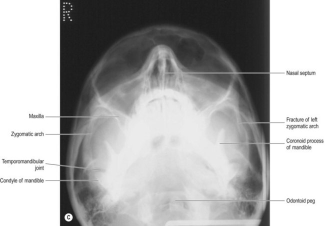
Requests that define the desired examination as ‘facial bones’ require a general OM and (sometimes) lateral survey of the area. OM projections are based on a position with the OMBL at 45°, using a range of caudal beam angles. More than one OM projection may be included in the survey, and two examples are shown of the 45° OM: without angulation in Figure 18.1B and with 30° caudal angulation in Figure 18.1C. Although discussion in the previous section shows that a 30° elevation of the OMBL from a perpendicular relationship to the IR has been suggested as a standalone projection for survey of facial bones,3 it does not appear to be universally adopted as such at present.
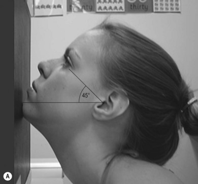
OM facial bones – basic projection (Fig. 18.1A,B,C)
Positioning
• The patient is seated, facing the IR
• The chin is placed in contact with the midline of the IR and the chin position is adjusted until the OMBL has been raised 45° from the horizontal
• The median sagittal plane (MSP) is perpendicular to the IR, which is assessed by checking that the external auditory meati (EAMs) or lateral orbital margins are equidistant from it

Beam direction and focus receptor distance (FRD)
1 Horizontal, at 90° to the IR and making an angle of 45° with the OMBL or
2 Initially horizontal, with caudal angulation applied according to requirements of the examination
100 cm FRD
Criteria for assessing image quality
• Orbits, zygomatic arches and mandible are demonstrated
• Symmetry of the facial bones on each side; equal distance of the lateral orbital margins from the outer table of temporal bones
• Odontoid process is visible between the angles of the mandible
Horizontal beam/0° beam angulation
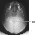
• Upper border of the petrous portion of the temporal bone is level with the apices of maxillary antra
• Zygomatic arches seen as a tight ‘C’ and reversed tight ‘C’ laterally
• Sharp image demonstrating the zygomae, nasal bones, orbits and mandible in contrast to the cranial vault, and the air-filled regions of the paranasal sinuses
15–20° caudal angle
• Zygomatic arches are more gently curved and elongated than with the perpendicular (horizontal) central ray
• Petrous ridge falls below maxillary antra and is likely to be indistinguishable
• TMJs are clearly demonstrated either side of the coronoid processes of the mandible
• Exposure factors are assessed as for the horizontal beam projection
30° caudal angle
• Zygomatic arches are slightly curved and elongated, when viewed from this inferior, half-axial, perspective
• Sharp image demonstrating contrast between the inferior orbital margins, maxillary sinuses and the zygomatic arches overlying the cranial vault. The frontal bone and upper orbital area may appear over-blackened but the nasal bones are clearly seen
| Common errors | Possible reasons |
|---|---|
| Asymmetry of facial structures | Rotation about MSP |
| Position of petrous ridge too high | Chin not raised enough. It has been noted that radiographers frequently ask patients to put their nose and chin onto the erect IR for this projection; this will only serve to raise the chin approximately 30°. It has also been noted that some imaging departments use this method with a 15° caudal angle, which only serves to clear the petrous ridge to the inferior margins of the antra; an almost identical image to the true OM 45° with horizontal beam will result, but there will be some distortion caused by application of the angle |
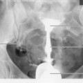
Lateral facial bones (Fig. 18.2A,B,C)
This projection is largely considered of little or no value3 but may still be used in some centres.
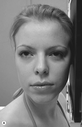
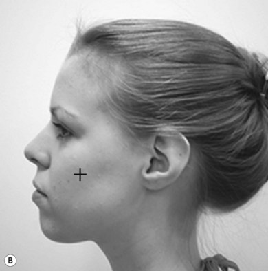

Figure 18.2 (A) Lateral facial bones; (B) centring for lateral facial bones; (C) lateral facial bones.
(C) Reproduced with permission from Bryan GJ. Skeletal anatomy. 3rd ed. Edinburgh: Churchill Livingstone; 1996 and Gunn C. Bones and joints. 4th ed. Edinburgh: Churchill Livingstone; 2002.
Positioning
• The patient is initially seated, facing the IR
• The trunk is brought as close as possible to the receptor unit and the patient is asked to sit with their spine as erect as possible. This helps the patient turn their head more easily into the required lateral position
• The head is turned through 90° to bring the affected side in contact with the IR
• The MSP is parallel to the IR; there should be no tilt or rotation of the head. This can be assessed by checking the midline of the cranium over the top and symmetry of the frontal bone and orbits
• Asking the patient to gently close their eyes will assist in maintenance of the position; as the radiographer leaves the receptor unit the patient will often follow this movement with their eyes and potentially affect the position of the head
Criteria for assessing image quality
• Superior orbital margins, symphysis menti, TMJs and nasal bones are demonstrated
• Superimposition of the malar processes of maxilla, orbital outlines and TMJs
• Sharp image demonstrating the malar processes of maxilla in contrast to the air-filled maxillary sinuses, and the orbits in contrast to other bones of the face. The mandible is seen in contrast to the soft tissues of the face. Nasal bones are over-penetrated
| Common errors | Possible reasons |
|---|---|
| Non-superimposition of the floor of the anterior cranial fossa; malar processes seen as one above the other; orbital outlines seen as one above the other | MSP tilted, usually with the upper part of the head tilted towards the IR. If a patient cannot comply with the required position, a compensating caudal angle can be used to reduce the effects of the tilt |
| Lateral orbital margins seen side by side and not superimposed; malar processes seen displaced in a horizontal direction | Head is rotated; this is often encouraged when the patient ‘slumps’ in their chair rather than sitting with their spine erect, as described in ‘positioning’ for this projection |