Flow Phenomena
Introduction
Unlike computerized tomography (CT) (with or without contrast), in which the appearance of flowing blood in a vessel is predictable, the appearance of flowing blood in MRI is much more complicated. Flowing blood or cerebrospinal fluid (CSF) can appear dark or bright depending on numerous factors, including, but not limited to, the following:
Velocity
Position of the slice containing the vessel relative to the rest of the slices
Echo number (even or odd)
Slice thickness
Flip angle
Gradient strength and rise time
Use of gradient moment nulling techniques
Use of spatial presaturation pulse
Use of cardiac gating
Chance of cardiac gating (pseudogating)
Types of Flow
In Chapter 18, we discussed two types of motion: random and periodic. Blood and CSF flow have a periodic-type motion. Furthermore, flow of blood can be divided into the following:
Laminar flow
Plug flow
Turbulent flow
Flow (stream) separation/vortex flow
These types of flow are depicted in Figure 26-1. Let’s discuss these separately.
Laminar Flow. This type of flow is seen in most normal vessels and has a parabolic profile. If the lumen radius is R, then the velocity v at position r would be
v(r) = Vmax (1 – r2/R2)
where Vmax is the maximum velocity in the center of the lumen. Therefore, the average velocity in the lumen is given by
Vave = Vmax/2
Plug Flow. This type of flow is usually seen only in large vessels (aorta) with high velocities. The velocity across the lumen is constant, thus yielding a flat velocity profile:
v(r) = Vmax = Vave = constant
Turbulence. This phenomenon is observed in abnormal vessels (e.g., distal to stenosis) or at bifurcations during which a random motion of fluid elements is observed. Vortex flow and large-scale recirculation zones (i.e., eddies) are other terms that refer to such random motions.
Flow (Stream) Separation. This phenomenon is observed near the wall of a vessel (e.g., in the proximal internal carotid artery) in which some of the flow is separated from the main streamline.
Question: What determines laminar versus turbulent flow?
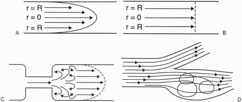 Figure 26-1. Types of flow. A: Laminar flow. B: Plug flow. C: Turbulent flow (distal to stenosis). D:Flow (stream) separation. |
Answer: A dimensionless number called the Reynolds number (Re) can predict the type of flow. It is given by
Re = (density × velocity × diameter)/viscosity
where density is in g/cm3, velocity is in cm/sec, diameter is in cm, viscosity is in centipoise or g/cm-sec, and Re has no units. If Re < 2100, then flow is laminar. If Re > 2100, then flow is turbulent.
Question: What is a typical blood flow velocity?
Answer: It depends on the vessel. Table 26-1 gives some examples.
The blood velocity may be much higher in abnormal conditions, such as in an arteriovenous fistula (AVF).
Question: What is the difference between flow and velocity?
Answer: A mathematical relationship exists between bulk or volumetric flow in a vessel lumen and the velocity of flow:
v = Q/A
where v is the average velocity (in cm/sec), Q is the bulk or volumetric flow (in cm3/sec), and A is the cross-sectional area of the vessel (in cm2).
Normal Appearance of Flowing Blood. Most flow effects can be attributed to one of the following:
Time-of-flight (TOF) effects
Motion-induced phase changes
TOF effects can lead to the following:
Signal loss (high-velocity signal loss or TOF loss)
Signal gain (flow-related enhancement [FRE])
Flowing blood can appear bright or dark. Three main independent factors result in each case:
↓ SI of flowing blood
high velocity
turbulent flow
dephasing
↑ SI of flowing blood
even-echo rephasing
diastolic pseudogating
FRE
Let’s discuss each of these separately.
Table 26-1 | ||||||||||
|---|---|---|---|---|---|---|---|---|---|---|
|
High-Velocity Signal Loss
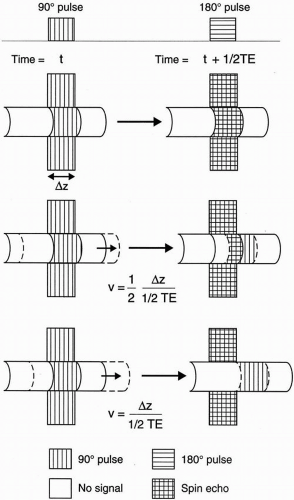
In SE imaging, the protons must be exposed to both a 90° and a 180° radio frequency (RF) pulse to give off a signal. High-velocity signal loss or TOF loss occurs when flowing protons do not remain within the selected slice long enough to be exposed to both RF pulses.
Figure 26-2 illustrates how the magnitude of signal loss is a function of the velocity. To see how this works, first recall the simple relationship among time, distance, and velocity:
Velocity = distance/time
or
v = d/t
The distance each proton in flowing blood has to travel within a slice is the slice thickness δz. The time between a 90° pulse and a 180° pulse is one-half TE.
Thus, if the velocity of flowing blood is
then protons flowing into the slice would be exposed only to the 90° pulse, and not to the 180° pulse, thus forming no signal or SE. Let’s give this velocity an arbitrary name vm, that is,
However, if the velocity were 0 (i.e., for stagnant blood), then an SE would be formed. If the velocity falls in between, only a fraction of the protons would form an SE. The fraction of protons escaping the 180° pulse is given by
Thus, the fraction of protons receiving both RF pulses is
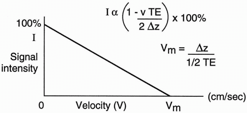
The signal intensity is, therefore, proportional to
Figure 26-3 illustrates the linear relationship between signal intensity (I) and velocity v. It is clear from this graph that if the velocity of flowing blood is at least equal to vm (i.e., v ≥ vm), then a flow void is observed.
 Figure 26-3. A plot of signal intensity versus velocity. The higher the velocity, the more the signal loss. |
Example
Suppose that the slice thickness δz = 1 cm and TE = 50 msec. What is the velocity at which flow void is observed?
Using the above formula, the velocity should be at least
which is seen in an artery.
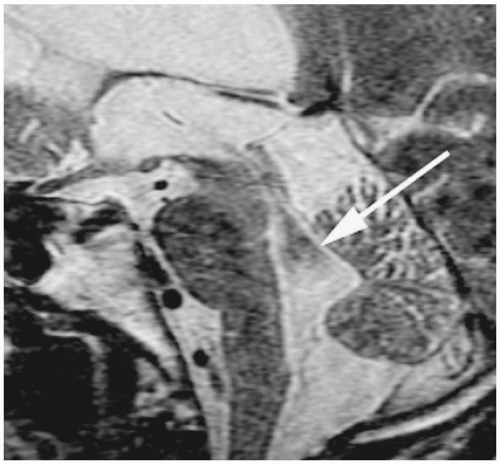
Therefore, vm is larger for thicker slices and smaller TEs, and vice versa (see Fig. 26-4 for an example).
N.B.: Remember that TOF losses only apply to SE imaging and not to GRE imaging
because, in GRE, the echo is formed via a single RF pulse and refocusing gradients (without a 180° pulse).
because, in GRE, the echo is formed via a single RF pulse and refocusing gradients (without a 180° pulse).
Turbulent Flow
In turbulent flow (with Re>2100), random flow exists that contains different velocity components (i.e., with different speed and direction of flow). Consequently, each of these components has different phases that tend to cancel each other out and result in no signal (flow void). This result can occur with low- or high-velocity flow (Fig. 26-5).
Dephasing
There are many causes of dephasing. One important cause is the so-called odd-echo dephasing. This phenomenon results in signal void on the first and other odd echoes. The protons in a voxel do not move at the same velocity across the lumen in laminar flow; thus, each precesses at a different frequency and accumulates a different phase. (Also see the discussion below on evenecho rephasing.)
Another cause of dephasing is intravoxel dephasing. Because of laminar flow, different velocities may exist within a voxel, thus leading to phase dispersion (incoherence) and signal loss. How to decrease intravoxel dephasing and increase SNR:
Decrease the voxel size (increase spatial resolution), either by increasing the matrix (trade-off: will reduce signal-to-noise ratio [SNR]) or by reducing the FOV (trade-off: may cause wraparound).
Stay updated, free articles. Join our Telegram channel

Full access? Get Clinical Tree


