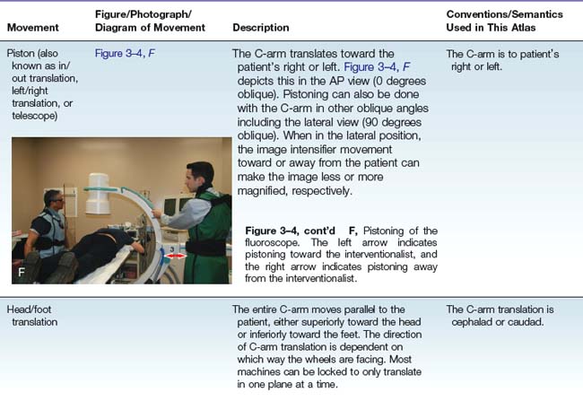
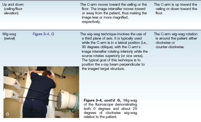
Chapter 3 Fluoroscopic Techniques/Procedural Pearls
Note: Please see page ii for a list of anatomical terms/abbreviations used in this book.
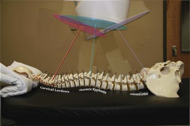

Confirming the Level
Lumbosacral
For a patient with normal spinal segmentation, identify the level in the anteroposterior (AP) view by counting cephalad from the sacrum; this is similar to the process of reading an MRI. In up to 15% of the population,1 a transitional segment may occur. Transitional segments are typically described as involving the lumbarization of the first sacral segment or the sacralization of the fifth lumbar segment. Rarely patients will have six lumbar vertebrae, although some consider these to be lumbarized S1 segments, because an L6 spinal nerve is typically not described. In fact, one study showed that L6 segments do indeed behave like S1 segments; in patients with only four lumbar vertebrae, the inferior-most lumbar segment, L4, behaves like an L5.2 This suggests that extra or missing ribs may add to counting confusion. Similarly, some patients may have aberrant segmentation of the cervicothoracic junction, the thoracolumbar junction, or both. Therefore, if a transitional segment is suspected, an MRI scout image is recommended for the purpose of counting caudad from C2 to the lumbosacral junction.3
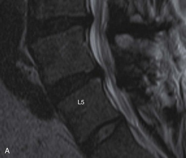
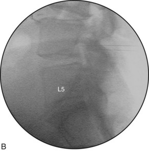
Ultimately, it is most important to correlate the patient’s clinical symptoms with the pathoanatomy visualized on the imaging that is obtained. Subsequently, images obtained during the procedure need be correlated with the same visualized pathoanatomy. For example, if a patient has right L5 or S1 symptoms and if the MRI suggests the sacralization of L5, an extrusion at L5-S1, and foraminal narrowing at L5, the key concept is to correlate the fluoroscopic lateral image with the sagittal MRI so that the proper levels are injected (Figure 3–5). Often practitioners will focus unnecessarily on the lumbar numbering (i.e., counting caudad from T12 rather than counting cephalad from the sacrum) instead of simply correlating the available imaging (i.e., the sagittal MRI and the lateral fluoroscopic imaging). It is imperative that the presence of the transitional segment is well communicated and documented so that all treating physicians are using the same terminology.
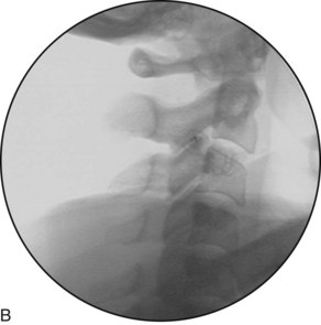
Cervical
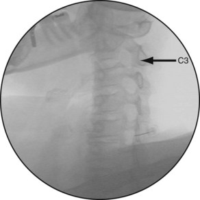
For a patient with normal spinal segmentation, identify the level by counting cephalad from the cervicothoracic junction in the AP view or down from C2 (dens) in the AP or lateral projection. For procedures that will be performed in the oblique projection (i.e., cervical transforaminal), identify the level by locating the most superior intervertebral foramen, which is the C2-C3 foramen where the C3 spinal nerve exits, and then count caudally (Figure 3–6).
“True” Anteroposterior View
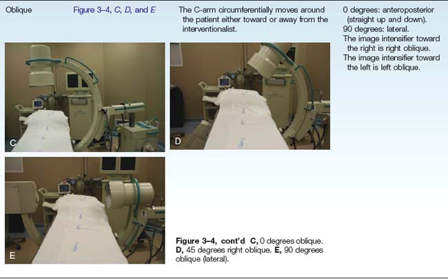
Each segment is not necessarily aligned with the others as a result of normal anatomy (i.e., lordosis, suboptimal positioning on the table), pathology (i.e., lateral or rotary scoliosis), or both. To optimize the efficiency and safety of a procedure, the proper obliquing and tilting of the C-arm to obtain a “true” AP view of the segment being investigated or treated is recommended. If the oblique adjustment of the C-arm is required to obtain a “true” AP view, geometry dictates that a similar adjustment will be required to obtain a “true” lateral view (see “True” Lateral View, later).
Oblique the C-Arm to Optimize the “True” Anteroposterior View
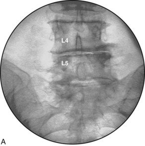
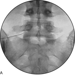
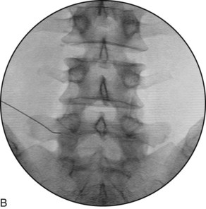
The C-arm image intensifier is obliqued to obtain a “true” AP view relative to the patient, with the spinous process at the midline of the vertebral body and equidistant from each pedicle. The “true” AP view is not necessarily at 0 degrees of obliquity. If the patient has multiple levels to be treated, a “true” AP should ideally be obtained each time for the corresponding level (Figure 3–7).
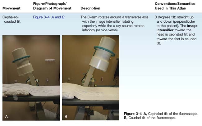
Tilt the C-Arm to Optimize the “True” Anteroposterior View
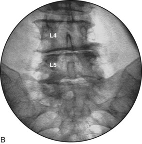
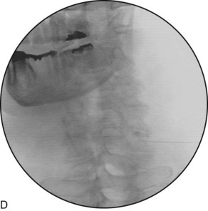
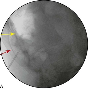
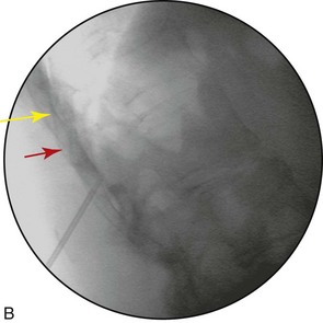
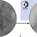
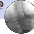
The vertebral body endplates, which are also known as the ring apophyses, cover both the superior and inferior horizontal surfaces of the vertebral body. The lining up of the vertebral body endplates is an important technique for obtaining a clear and direct view of the target region for many procedures. For example, when performing discography, the trajectory view requires direct parallel visualization of the endplates. This fluoroscopic view is obtained with the cephalad or caudad tilt of the C-arm image intensifier. This optimizes the superior endplate of the inferior vertebral body, which is visualized as a solid horizontal line rather than as an ellipse (Figure 3–8).
“True” Lateral View
Oblique the C-Arm to Optimize the “True” Lateral View
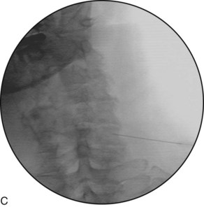
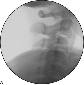
For the cervical spine, a “true” lateral view may be obtained by lining up the lateral masses. If the patient is prone or supine, this is accomplished with the use of the wig-wag, and it may require additional obliquing of the C-arm or the table. If the patient is in a side-lying position, this is accomplished by tilting and occasional additional obliquing. Sometimes each level must be lined up individually (Figure 3–9).
For the thoracic spine, a “true” lateral view may be obtained by lining up the ribs (Figure 3–10).
For a patient with scoliosis, the lateral view is obtained by obliquing the C-arm 90 degrees from the angle that was used to best visualize the AP view (Figure 3–11).
Related posts:
 Atlantoaxial Joint Intraarticular Injection
 Lumbar Zygapophysial Joint Nerve (Medial Branch) Radiofrequency Neurotomy, Posterior Approach
 Cervical Interlaminar Epidural Steroid Injection, Paramedian Approach
Stay updated, free articles. Join our Telegram channel

Full access? Get Clinical Tree


