Study – tibiotalar joint injection
Author
Accuracy (%)
Palpation
Wisniewski et al. [4]
88
Ultrasound guided
Kirk et al. [5]
100
Scanning Techniques and Anatomy to Identify
Scan the anterior aspect of the joint in the sagittal plane to visualize the anterior recess. Identify the distal tibia, the talar head, and the talar dome in between them with its thin anechoic cartilage. The joint capsule extends as a hyperechoic line between the distal tibia and the talar head. Immediately deep to the capsule is the intra-articular fat pad, which is triangular shaped, like a wide arrowhead pointing posteroinferiorly into the joint space. Sweep medially and laterally to visualize the surface of the talar dome, exploring for effusion or osteochondral defects. Rotate the transducer 90° to the axial plane. Position it slightly inferior to the distal tibia, and identify the tendons of the tibialis anterior, extensor hallucis longus, and extensor digitorum longus muscles. Identify and avoid the anterior tibial artery and deep fibular nerve (Fig. 7.1).
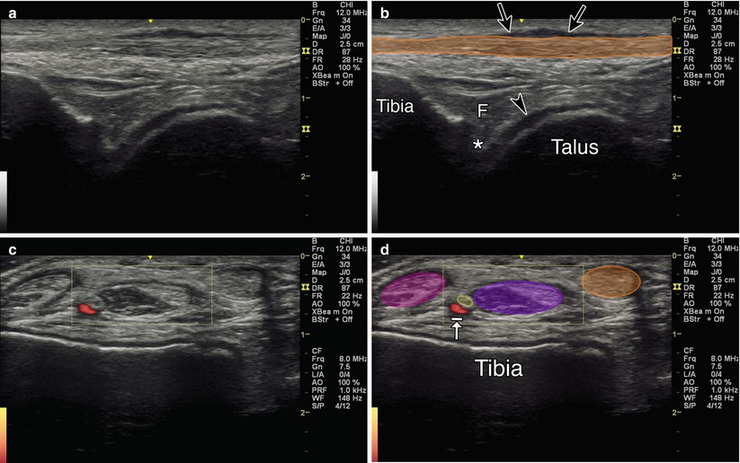
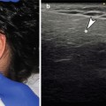
Fig. 7.1
(a) Sagittal view of tibiotalar joint. (b) Orange indicates tibialis anterior tendon. Arrowhead indicates hyaline cartilage. Arrows indicate fluid within tibialis anterior tendon sheath. Asterisk indicates joint space. F fat pad. Tibia and talus labeled. (c) Axial view of tibiotalar joint. (d) Orange indicates tibialis anterior muscle. Purple indicates extensor hallucis longus muscle. Yellow indicates deep peroneal nerve. Arrow with stop indicates the anterior tibial artery. Magenta indicates extensor digitorum longus muscle
Injection Technique: In-Plane Sagittal Anterior Approach [2, 8]
Patient positioning: Lay the patient supine, knee flexed with foot flat. Alternatively, the ankle can rest off the end of the table with the foot passively plantar flexed.
Probe positioning: Position the transducer so that the center of the screen is in between the extensor hallucis longus and tibialis anterior, and then rotate back to the sagittal plane for the injection (Fig. 7.2a).
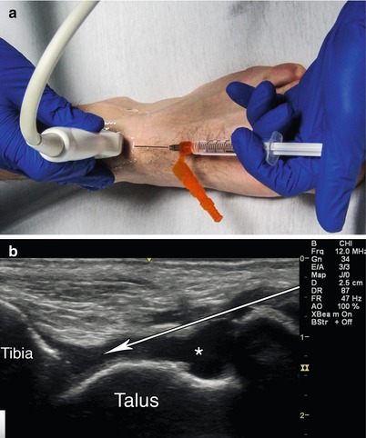
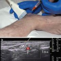
Fig. 7.2
(a) Example of sagittal probe position over anterior tibiotalar joint with in-plane needle position. (b) Sagittal view tibiotalar joint. Arrow indicates needle trajectory. Asterisk indicates effusion. Tibia and talus labeled
Markings: Identify the dorsalis pedis artery, deep fibular nerve, tibialis anterior tendon, and extensor hallucis longus tendon.
Needle position: Enter in-plane and maintain a relatively steep angle to avoid scraping the talar dome, which can sometimes appear contiguous with an overlying effusion.
Safety considerations: Avoid the dorsalis pedis artery, deep fibular nerve, tibialis anterior tendon, and extensor hallucis longus tendon.
Pearls:
There should be minimal resistance during injection.
Superior migration of the overlying fat pad further confirms intra-articular spread of injectate.
If visualization is poor, gel standoff can be used.
Equipment needed:
Medium-frequency linear array transducer (8–12 MHz)
22–25G 1.5″ needle
0.5–1.0 mL of steroid preparation
1–3 mL local anesthetic
Subtalar Joint (Talocalcaneal Articulation)
The subtalar joint is comprised of three articulations between the talus and the calcaneus. The anterior facet is located above the anteromedial corner of the calcaneus, the middle facet is located medially, and the posterior facet is located posteriorly. The anterior and middle facets are contiguous and together comprise the anterior subtalar articulation [9, 10]. The current literature only focuses on the posterior articulation, perhaps because it is the largest of the three and presumably bears the majority of the weight across the joint. In one study blind injection using an anterolateral approach resulted in a 27 % rate of extravasation into the surrounding structures in an unpredictable distribution [9]. The posterolateral approach was found to be superior (91.2 % vs. 67.6 %) [10]. A study comparing ultrasound-guided anterolateral, posterolateral, and posteromedial approaches resulted in 100 % accuracy for all three methods, with rates of extravasation 25, 25, and 8.3 %, respectively [11]. Furthermore, using dynamic ultrasound may allow a smoother needle trajectory, minimizing contact with surrounding structures [12].
Scanning Techniques and Anatomy to Identify
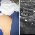
The posteromedial approach has been shown to have the best accuracy (reference above). Position the patient side lying with the medial aspect of the affected joint upwards and a rolled towel beneath the lateral malleolus to place the ankle in subtalar eversion. Place the transducer in the coronal plane with the proximal end on the medial malleolus and the distal end over the sustentaculum tali of the calcaneus. Identify the middle subtalar facet, which appears as an anechoic space between the sustentaculum tali and the talus. Sweep the transducer posteriorly to locate the anechoic medial aspect of the posterior subtalar joint line (Fig. 7.3).
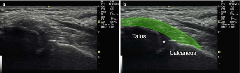
Fig. 7.3
(a) Coronal view of posterior subtalar joint. (b) Green deltoid ligament. Asterisk indicates subtalar joint. Talus and calcaneus labeled
Injection Technique: Out-of-Plane Coronal Posteromedial Approach
Patient positioning: Lay the patient on their side with the medial aspect of the affected ankle facing upwards. A rolled-up towel can be placed below the lateral malleolus to promote subtalar eversion.
Probe positioning: Place the probe in the coronal plane just posterior to the sustentaculum tali and medial malleolus (Fig. 7.4a).
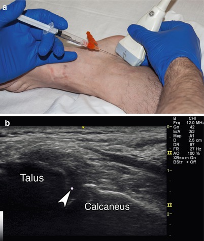
Fig. 7.4
(a) Example of coronal probe position over posteromedial subtalar joint with out-of-plane needle position. (b) Coronal view over subtalar joint. Arrowhead indicates needle tip. Talus and calcaneus labeled
Markings: Identify and avoid the tarsal tunnel.
Needle position: Insert the needle out-of-plane, anterior to the transducer, and angle it posteriorly and laterally.
Safety considerations: Avoid the tibialis posterior, flexor digitorum, and flexor hallucis longus tendons and the plantar nerves and arteries.
Pearls:
Subtalar alignment can vary based on the type of pathology
Gel standoff can be used to optimize trajectory
Equipment needed:
High-frequency linear array transducer
22–25G 1.5″ needle
0.5 mL of steroid preparation
1–3 mL local anesthetic
Medial (Deltoid) Ligament
Ankle sprains have been found to account for 15–40 % of all athletic injuries [13–15]. The medial ligament is composed of the posterior tibiotalar, tibiocalcaneal, tibionavicular, and anterior talotibial ligaments. The complex is stronger, more stable, and less commonly injured than the lateral ligaments. It is a major contributor to ankle stability during weight bearing and is the primary limiter of lateral talar shift and talar external rotation. External rotation fractures at the lateral malleolus are associated with medial ligament injuries. Local swelling, tenderness, and ecchymosis have been shown to be unreliable in establishing a diagnosis. MRI is useful for visualization of ligament irregularity but is unable to demonstrate instability. A 2004 study found the most commonly used radiographic finding for deltoid ligament rupture and medial ankle instability (the medial clear space) to be unreliable [16]. In a prospective study of 12 patients with supination external rotation injuries, ultrasound accurately diagnosed acute deltoid ligament rupture with a sensitivity and specificity of 100 % [8]. No current evidence supports the use of local injections for medial ligament injuries. However, emerging studies seem promising for the eventual development of an appropriate injectate.
Scanning Techniques and Anatomy to Identify
Position the patient in side-lying position with the medial aspect of the affected joint facing upwards. Use a rolled-up towel below the lateral malleolus to place the ankle in subtalar eversion. Maintain the proximal end of the transducer over the medial malleolus and rotate the distal end to the neck of the talus for the anterior tibiotalar ligament, the navicular bone for the tibionavicular ligament, the sustentaculum tali for the tibiocalcaneal ligament, and the posterior process of the talus for the posterior tibiotalar ligament, which sits deep to the tibialis posterior tendon (Fig. 7.5).
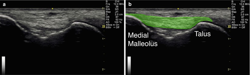
Fig. 7.5
(a) Coronal view of anterior tibiotalar ligament. (b) Green indicates tibiotalar component of deltoid ligament. Medial malleolus and talus labeled
Injection Technique: In-Plane Coronal Approach
Patient positioning: Lay the patient on their side with the medial aspect of the affected ankle facing upwards. A rolled-up towel can be placed below the lateral malleolus to promote subtalar eversion.
Probe positioning: Maintain the proximal end of the probe over the medial malleolus while rotating the distal end to the talar neck for the anterior tibiotalar ligament, the navicular bone for the tibionavicular ligament, the sustentaculum tali for the tibiocalcaneal ligament, and the posterior process of the talus for the posterior tibiotalar ligament, which sits deep to the tibialis posterior tendon (Fig. 7.6a).
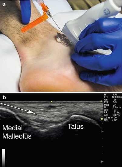
Fig. 7.6
(a) Example of coronal probe position with gel standoff over anterior tibiotalar ligament with in-plane needle position. (b) Coronal view of anterior tibiotalar ligament. Arrow indicates needle trajectory. Medial malleolus and talus labeled
Markings: Identify the tarsal tunnel and avoid inadvertent puncture.
Needle position: Enter with a superficial trajectory, in-plane with the probe.
Safety considerations: Avoid the posterior tibialis, flexor digitorum, and flexor hallucis longus tendons, and the plantar nerves and arteries.
Pearls:
Manipulate the ankle to provide slack vs. tension to the structures of interest while scanning.
Placing tension on the ligament may help the “feel” of the needle tip piercing its surface.
Placing slack on the ligament may cause it to appear thicker, resulting in better visualization.
Equipment needed:
High-frequency linear array transducer
25G 1.5″ needle
0.5 mL of injectate
1–3 mL local anesthetic
Lateral Ligament Complex
The lateral ligament complex consists of the anterior talofibular ligament (ATFL), the calcaneofibular ligament (CFL), and the posterior talofibular ligament (PTFL) [17, 18]. In one study, point tenderness over the ATFL and CFL correlated with ligament rupture 52 and 72 % of the time, respectively. 71 % of patients with a positive anterior drawer sign, 68 % of patients with a positive talar tilt, 70 % of patients with ≥4 cm of swelling under the lateral malleolus, and 91 % of patients with such swelling in combination with point tenderness were shown to have lateral ligamentous injury [19]. Ultrasound has been shown to have the diagnostic accuracy of 95 % for ATFL tears and 90 % for CFL tears (Table 7.2) [17, 18].
Table 7.2
Anatomy of lateral ligament complex
ATFL | CFL | PTFL | |
|---|---|---|---|
Origin | 1 cm proximal to the distal tip of the fibula | Distal tip of the fibula | 10 mm proximal to the distal tip of the fibula |
Insertion | lateral talar neck | Calcaneus | Posterior talus |
Size | 6–10 mm wide × 10 mm long × 2 mm thick | Cylindrical in shape, 20–25 mm length × 6–8 mm diameter | |
Notes | Weakest, most commonly injured | Attachment point of the peroneal tendon sheath | Strongest, least commonly injured |
Scanning Techniques and Anatomy to Identify
Position the patient on their side with the lateral aspect of the affected ankle facing upwards. Use a rolled-up towel under the medial malleolus to place the ankle in subtalar inversion. For the ATFL, passively plantar flex the ankle and place the proximal edge of the transducer over the anterior aspect of the lateral malleolus, with the distal edge over the talus, reaching horizontally towards the midfoot. Visualize the lateral malleolus, the talus, and the ligament between them. For the CFL place the ankle in neutral and position the proximal edge of the transducer over the lateral malleolus. Aim the distal edge inferiorly and slightly posteriorly. Dorsiflexing the ankle may help visualize the ligament by placing it in tension. Immediately superficial to the CFL at the level of the superior edge of the calcaneus, the fibular tendons appear in cross section. The sural nerve runs inferior to these tendons, at a similar depth (Fig. 7.7) [21].
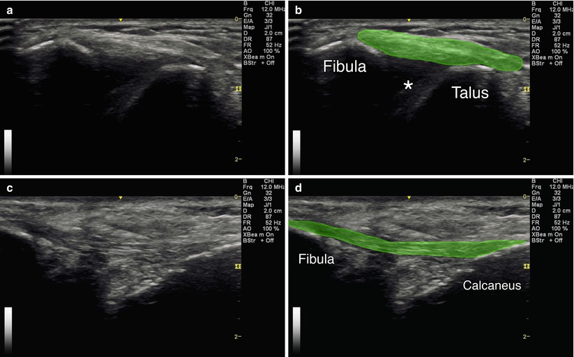
Fig. 7.7
(a) Axial view of the ATFL. (b) Green indicates the ATFL. Asterisk indicates joint space. Fibula and talus labeled. (c) Coronal oblique view of the CFL. (d) Green indicates the calcaneofibular ligament. Fibula and calcaneus labeled
Injection Techniques: In-Plane Axial Approach
Patient positioning: Lay the patient on their side with the lateral aspect of the affected ankle facing upwards. A rolled-up towel can be placed under the medial malleolus to promote subtalar inversion. Place the ankle in plantar flexion for ATFL and dorsiflexion for CFL.
Probe positioning: Maintain the proximal edge over lateral malleolus. Place the distal edge over the talus in the axial plane for the ATFL (Fig. 7.8a). Place the distal edge over the calcaneus in the coronal plane for the CFL.
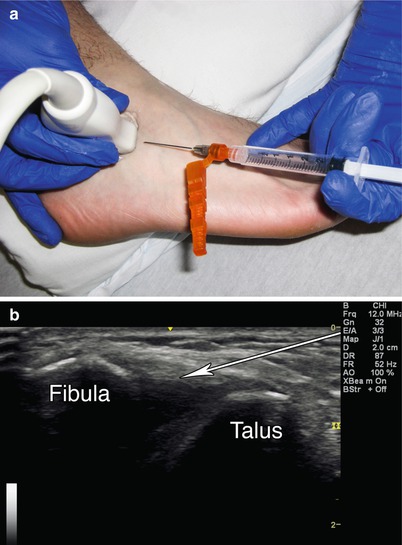
Fig. 7.8
(a) Example of axial probe position over ATFL with in-plane needle approach. (b) Axial view of ATFL with arrow indicating needle trajectory. Fibula and talus labeled
Markings: Identify and avoid the sural nerve.
Needle position: Enter the skin with a superficial trajectory, in-plane with the probe.
Safety considerations: Avoid the sural nerve, peroneal tendons, and lesser saphenous vein.
Pearls:
Manipulate the ankle to provide slack vs. tension to the structures of interest while scanning.
Placing tension on the ligament may help the “feel” of the needle tip piercing its surface.
Placing slack on the ligament may cause it to appear thicker, resulting in better visualization.
The ATFL is contiguous with the ankle joint capsule and can appear as a discrete capsular thickening.
The CFL is the only extra-articular ligament within the lateral complex.
Equipment needed:
High-frequency linear array transducer
25G 1.5″ needle
0.5 mL of steroid preparation
1–3 mL local anesthetic
Retrocalcaneal Bursa
The retrocalcaneal bursa is located immediately superior and deep to the distal insertion of the Achilles tendon on the posterior calcaneus. Ultrasound has been shown to accurately visualize the bursa and guide targeted intervention [20]. One study suggests that merely visualizing the bursa on ultrasound suggests pathology [22]. An anterior to posterior diameter greater than 2.5 mm is generally considered abnormal [15]. The Achilles (retro-Achilles/subcutaneous calcaneal) bursa is larger and located superficial to the Achilles tendon at the same level. Any evidence of fluid here on ultrasound is pathologic.
Scanning Techniques and Anatomy to Identify
Position the patient prone with the ankle and foot hanging off the table edge. Place the transducer in the longitudinal plane directly over the Achilles tendon. Visualize the Achilles tendon, its calcaneal insertion, and Kager’s fat pad, which is deep to the tendon immediately proximal to its insertion. The retrocalcaneal bursa sits in between these three structures and is not always visible. Rotate the transducer 90° into the axial plane and identify the aforementioned structures [23]. The fat pad should not be visible since it is directly superior to this viewing level, above the bursa. Moving the transducer superiorly and inferiorly will bring the fat pad and calcaneus into view, respectively (Fig. 7.9).
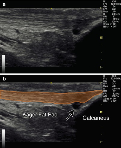
Fig. 7.9
(a) Sagittal view of Achilles tendon and retrocalcaneal bursa. (b) Orange indicates Achilles tendon. Arrow indicates retrocalcaneal bursitis. Kager’s fat pad and calcaneus labeled
Injection Technique: In-Plane Axial Approach
Patient positioning: Lay the patient prone with the foot hanging off the table edge.
Probe positioning: Place the probe in the sagittal plane directly midline over the Achilles tendon at its calcaneal attachment. Center the bursa on the screen in the sagittal plane, then rotate into the axial plane. Use Doppler to identify any surrounding blood vessels and use a medial or lateral approach accordingly (Fig. 7.10a).
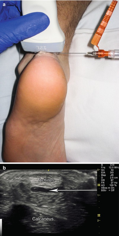
Fig. 7.10
(a) Example of axial probe position over retrocalcaneal bursa with in-plane needle position. (b) Arrow indicates needle trajectory into retrocalcaneal bursitis. Cross section of Achilles labeled. Calcaneus labeled
Markings:
Needle position: Enter the skin in-plane with the transducer from the medial or lateral side.
Safety considerations: Avoid the sural nerve and any obvious vessels with the lateral approach.
Pearls:
Doppler can also be used to confirm hyperemia within the bursa.
Equipment needed:
High-frequency linear array transducer
25G 1.5″ needle
0.5 mL of steroid preparation
1–3 mL local anesthetic
Achilles Tendon/Paratenon
Ultrasound is useful in identifying small tears, partial ruptures, retrocalcaneal bursitis, and chronic tendinosis [24–26]. Corticosteroid injection is generally not recommended due to the risk of rupture; however, in the setting of acute and/or chronic inflammation, corticosteroid injection to the surrounding paratenon sheath can alleviate symptoms. If symptoms become chronic, dry needling and injection of reparative substances are potential interventions (Table 7.3) [27].
Table 7.3
Accuracy of achilles tendon injections
Study – Achilles tendon injection | Author | Accuracy (%) |
|---|---|---|
Ultrasound guided (unblinded) | Reach et al. [2] | 100 |
Scanning Techniques and Anatomy to Identify
Position the patient prone with the foot hanging off the end of the examination table. A pillow under the distal tibia can be used for comfort. Scan both views of the tendon from the myotendinous junction to the calcaneus. In the transverse plane, scan on both sides of the tendon to visualize the paratenon envelope or peritendinous sheath [1, 8]. Passive plantar/dorsiflexion may improve visualization of the tendon [28]. Look for the retro-Achilles and retrocalcaneal bursae. Power Doppler settings may be utilized to visualize neovascularization and inflammation [1]. Tendinosis appears as areas of hypoechogenicity with intact fibrillar structure. Thickening of the tendon or a relatively diffuse convex shape at the attachment of the tendon is abnormal [29, 30]. Generally, the injection approach is medial to avoid injuring the sural nerve [31–33]. Alternatively, inject the paratenon at the midportion level (2–6 cm proximal to the Achilles tendon insertion into the calcaneus) (Fig. 7.11) [34].
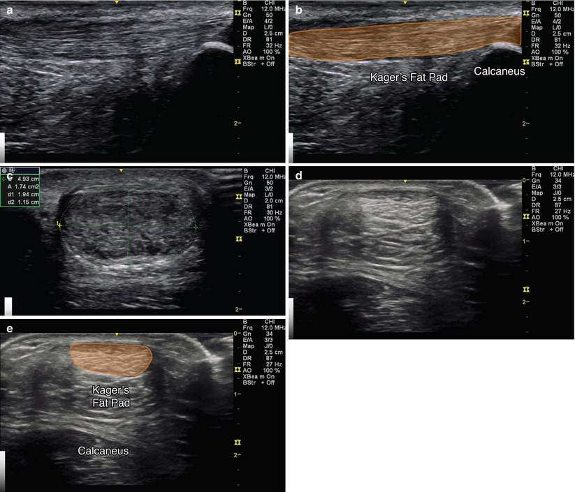
Fig. 7.11
(a) Sagittal view of Achilles tendon. (b) Orange indicates Achilles tendon, Kager’s fat pad and calcaneus labeled. (c) Axial view of Achilles tendinosis. (d) Axial view of Achilles tendon (e) Orange indicates Achilles tendon. Kager’s fat pad and calcaneus labeled
Injection Technique: In-Plane Sagittal Approach
Patient positioning: Lay the patient prone with foot resting off the end of the table.
Probe positioning: Place the probe in the sagittal plane for initial visualization and scan proximally and distally, looking for focal thickening and/or fluid (Fig. 7.12a). The probe can also be rotated 90° to the axial plane for an in-plane axial approach.
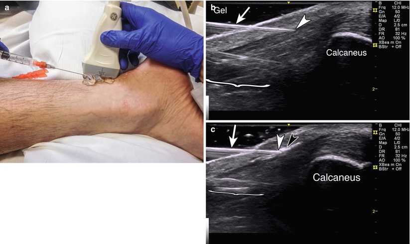
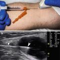
Fig. 7.12


(a) Example of sagittal probe position with gel standoff over Achilles tendon with in-plane needle position. (b) Example of in-plane injection with arrowhead in tendon sheath. Arrow indicates needle. Gel shows standoff positioning. Bracket indicates needle reverberation. Calcaneus labeled. (c) Black arrowhead indicates steroid flash within in sheath superficial to the Achilles tendon. White arrowhead indicates needle tip. Arrow indicates needle. Bracket indicates needle reverberation. Calcaneus labeled
Related posts:
Stay updated, free articles. Join our Telegram channel
Full access? Get Clinical Tree
