Fig. 1
Block diagram of MEG measurement system
Considering the high price of Ni-alloy materials used for the magnetic shielding, it is desirable to use gradiometers than magnetometers to reduce the amount of Ni-alloy. Currently two types of hardware gradiometers are used, that is, axial or planar gradiometer, either in wire-wound or thin film structure. Alternatively, software gradiometers having reference sensors located at some distance from the signal sensors and software optimization to have best signal-to-noise ratio can be used.
A SQUID is basically a converter from magnetic flux to voltage. However, amplitudes of SQUID voltage output are quite small for typical input range of MEG signals, requiring a low-noise preamplifier to readout the SQUID output. To simplify the readout electronics of a multichannel SQUID system, the SQUID output voltage should be large enough, otherwise a rather complex readout scheme is needed (Drung 1996; Pizzella et al. 2001).
To increase the field detection area of a SQUID magnetometer or gradiometer, flux transformer is used where a larger pickup coil, typically about 20 mm diameter, picks up the magnetic field and converts it into flux through the input coil. The intrinsic flux noise of SQUID increases with the increase of SQUID inductance, thus the loop size of SQUID needs to be minimized. However, for effective coupling of magnetic flux with the input coil, the SQUID loop size has a certain practical limit, typically about 100 μm.
2 SQUID Sensors
2.1 SQUID as a Magnetic Field Sensor
In the operation of a SQUID, four basic superconducting phenomena are used: (i) complete loss of electric resistance at temperatures below the critical temperature, (ii) perfect diamagnetism having no magnetic flux inside the superconductor, (iii) quantization of magnetic flux in a superconducting ring, (iv) Josephson effect. Most of the present MEG systems use low-temperature Nb-based SQUIDs. Nb has a superconductive transition temperature of about 9.2 K, and is a refractory and reliable material against repeated thermal cycling between 4.2 K and room temperature. And the noise characteristics of SQUIDs made from Nb/AlOx/Nb Josephson junction show low leakage current in the low frequency range, which is an important requirement for measuring low-noise MEG measurement. The fabrication technology of Nb SQUID sensors is now well established and fabrication of many sensors on Si-wafers can be done (Lee et al. 1999). The typical size of the SQUID chip is about 10 mm2, including pads for wire bonding (Al and Nb).
Figure 2 shows the principle of measuring an MEG signal using a SQUID. For the effective pickup of magnetic field signal, a superconductive flux transformer is used, consisting of a pickup coil of a much larger diameter than the SQUID loop and a multi-turn input coil integrated directly on the SQUID loop. When a magnetic field is applied to the pickup coil, a screening current is generated in the superconductive flux transformer circuit, and this current is converted into magnetic flux through the input coil and magnetic coupling with the SQUID loop. In a typical design of flux transformer and SQUID, about 0.5 nT of magnetic field in the pickup coil corresponds to flux transfer of 1 Φ0 into the SQUID loop.


Fig. 2
Principle of measuring MEG signal using SQUID
2.2 Pickup Coil
Typical dimensions of SQUID loops are about 0.1 mm. Thus, to increase the detection efficiency, pickup coils of a diameter larger than 10 mm is usually needed. Among various types of pickup coils, magnetometers or hardware first-order gradiometers are now used in present MEG systems. Figure 3 shows examples of pickup coils.
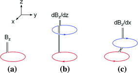

Fig. 3
Typical pickup coils used in MEG measurements. a Magnetometer, b axial first-order gradiometer, and c planar first-order gradiometer
Magnetometers have the best sensitivity to both deep and shallow sources. At the same time, however, it is more vulnerable to external noises. The optimum choice of a pickup coil depends on the details of the measurement condition; thickness of the MSR, strength of environmental noises, and signals to be measured. Inside a thick MSR or in a quiet location, magnetometers as the sensing element are preferable. In urban clinics or laboratories, there is often a limitation in the thickness or weight of the MSR. Thus, moderate or medium-thickness MSRs, in combination with gradiometers, is the best combination. Generally speaking, axial gradiometers have longer baselines than planar gradiometers, so that it has better sensitivity to deep sources than planar gradiometers. For shallow sources, planar gradiometers have better sensitivity when the axis of current dipole (y-axis in Fig. 3c) is perpendicular to the field derivative direction of the gradiometers (x-axis in Fig. 3c).
A planar gradiometer can be made on a single wafer, that is, the planar pickup coil can be integrated on the same wafer as the SQUID loop. For example, in the Neuromag system, 2 perpendicular planar gradiometers and magnetometer are integrated on the same element (wafer) (Parkkonen 2010).
A possible disadvantage of the axial gradiometer is the relative complex process in assembling the axial gradiometer, and it needs superconductive connection (bonding) between pickup coil wires and input coil pads. For the superconductive connection between the pickup coil and the input coil, usually superconducting Nb blocks or strips with screw terminals are used. To eliminate pickup area of the magnetic field due to the superconducting connection structure, Nb blocks are sometimes shielded using a superconducting tube (Ketchen 1987; ter Brake et al. 1992; Dössel et al. 1993). Since this superconducting block and tube introduces distortion of magnetic fields, and they are installed at a sufficiently large distance from the compensation coil of the gradiometer to maintain the balancing of the gradiometer against the external fields, as shown in Fig. 4a. Increased length of the gradiometer requires higher level of liquid He to keep both SQUID and pickup coil superconducting. In order to increase the refill interval of liquid He, it is desirable to position the SQUIDs as close as possible to the gradiometers. Recently, some improvements were made to remove the shielding tube, so that the SQUID is positioned at about 20 mm from the compensation coil. But, the stray pickup area due to the superconducting connection structure generates imbalance of roughly few percent. A novel method to simplify the superconductive connection method and to reduce the stray pickup area is direct bonding of Nb wire between pickup coil wires and input coil pads. Thus, the fabrication process of the gradiometer became simpler and the total length of the gradiometer can be shortened (Lee et al. 2009). Considering that the residual fields inside the MSR are not highly homogenous, the intrinsic balancing of the gradiometers needs to be as large as possible with simple fabrication process.
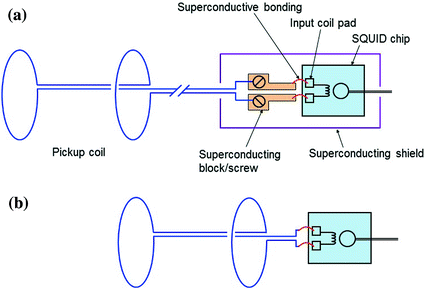

Fig. 4
Structure of axial gradiometer. a Conventional axial gradiometer having Nb block and screw inside a superconducting shield. b Simplified axial gradiometer structure with direct bonding between pickup coil and input coil
3 SQUID Electronics
3.1 Flux-Locked Loop Electronics
The voltage output of a SQUID is periodic like a sinusoidal function and nonlinear with respect to the input flux as shown in Fig. 5a. To get a linear response against the input flux signal, a special operation scheme, called flux-locked loop (FLL), is used. In the FLL operation (Fig. 5b), the flux in the SQUID loop is locked at a constant point using a negative feedback circuit, and the feedback voltage (or feedback flux through the feedback coil) is measured as the final output. Figure 6 shows a schematic circuit diagram of standard-type FLL operation. Since the amplitude of SQUID output against input MEG signals is small, care should be taken in detecting the SQUID output. For example, a typical MEG signal, say, 100 fT corresponds to about 0.2 mΦ0 in the SQUID loop, which generates a voltage signal of 20 nV (for a typical flux-to-voltage transfer of 100 μV/Φ0). To detect this level of voltage signal, careful design of a room-temperature preamplifier is needed. For economic operation of multi-channel SQUIDs for MEG systems, simple and compact room-temperature readout electronics are required. For the simple structure of the FLL circuits, output voltages and flux-to-voltage transfers of the SQUIDs should be large enough so that the contribution of preamplifier input noise is negligible in direct readout mode (Drung 1996; Drung and Mück 2004). A double relaxation oscillation SQUID (DROS), based on the relaxation oscillation of a hysteretic SQUID and a reference junction, provides large flux-modulated voltage output and a steep flux-voltage transfer coefficient (Adelerhof et al. 1994; Lee et al. 1999; 2005). One example of a DROS design is shown in Fig. 7, which enables direct measurement of SQUID output using room-temperature preamplifiers, and makes the FLL circuits compact using DC bias current. In the FLL or internal feedback scheme, there is crosstalk between adjacent pickup coils. Induced current in the flux transformer generates a magnetic field, which can be picked up by nearby pickup coils. This stray coupling can be eliminated by using the feedback scheme called external feedback or current feedback loop, in which the current in the flux transfer circuit is kept constant (ter Brake et al. 1986).
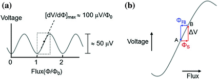
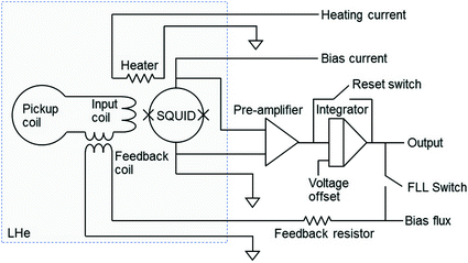
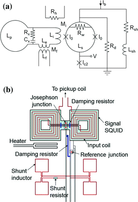

Fig. 5
Response curve of the SQUID to magnetic flux. a SQUID output voltage as a function of flux signal. b Principle of flux-locked loop operation. Change of signal flux (ΦS) is compensated by a negative feedback flux (ΦFB) applied to the SQUID loop. Φ0 is the flux quantum (=2.07 × 10⁻¹⁵ Wb)

Fig. 6
Schematic diagram of the standard flux-locked loop circuit. When the feedback current is applied to the flux transformer circuit, the total flux in it is maintained constant

Fig. 7
Design of double relaxation oscillation SQUID (DROS). a Schematic circuit diagram of DROS. b Design layout of DROS in the SQUID loop area
Superconductivity is maintained under critical condition, that is, below critical temperature, critical current, and critical field. If the SQUID is exposed to high magnetic field or transient electric pulses, magnetic flux can be trapped in the thin film SQUID. Trapped flux can deteriorate the performance of the SQUID or even make normal SQUID operation difficult. Trapped fluxes can be removed by applying a current pulse of about 1 W, typically 0.1 ~ 1 s duration, to the SQUID. The heater is placed close to the SQUID loop. During heating, the temperature of SQUID temporarily rises to just above its superconductive transition temperature, at the expense of temporary slight evaporation of liquid He.
3.2 Analog Signal Processing
The voltage output of a FLL circuit is too small to be measured directly by analog-to-digital converter using a computer. Thus, intermediate amplifier and filters are used which consist of high pass, low pass, power-line elimination filter and amplifier. Typical cutoff frequencies for high and low pass filters are 0.01 ~ 0.1 and 100 Hz, respectively. Amplification is 100 or 1,000 times. Use of analog filters makes acquisition easier and real-time monitoring of the acquisition process easier. However, analog filters can change the shape of the signal waveforms and introduce phase distortions. In addition to the separate space needed to house the analog signal processing (ASP) circuits, an ASP usually consumes more electrical power than the FLL circuit does. Recent MEG systems digitize the output of FLL directly, and measure signals through optical fibers. Advantages of using optical readout are (i) reduced power consumption, (ii) compact electronics and reduced installation space by eliminating the ASP box, (iii) elimination of electric interference from outside of MSR, and (iv) increased dynamic range of FLL output. Figure 8 shows the comparison of SQUID output measurement systems with conventional ASP circuits (Fig. 8a) and ASP-free readout system (Fig. 8b).
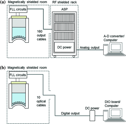

Fig. 8
Schematic diagrams of the SQUID output measurement systems. a Conventional type with ASP circuit and analog-to-digital converters. b ASP-free readout with signal transmission using optical cables
4 Dewar
Modern MEG systems have helmet-shaped dewars covering the whole head. Depending on the populations to be measured, there is slight variation in the shape of the helmet. For example, a dewar for Caucasian people has a longer dimension along the frontal-occipital direction than the dewars for Asian population. The size of the dewar should be large enough to accommodate most of the population, but too large of a helmet size increases the distance between the sensor surface (measurement points) and the head surface at room temperature (Vrba et al. 2002). This distance is about 20 mm or less. SQUID sensors can be installed either in the liquid He reservoir or the vacuum space with tight thermal contact with the He reservoir (coil-in-vacuum).
He dewar is made of fiberglass reinforced plastic, which is non-magnetic and mechanically strong with low thermal expansion coefficient. Between the inner and outer vessel, multiple (around 50) layers of superinsulation (SI) and vapor-cooled thermal shields are installed. The SI is made from thin aluminum film deposited on flexible insulating substrate. To minimize the thermal magnetic noise induced from the metallic film, the surface area of the aluminum is reduced by dividing it into an island structure or by crinkling it. The thermal shield also should be made to minimize the thermal noise. It is made of copper coil foil, which is a woven fabric, made of thin enameled copper wires. Improper installation of SI and the thermal shield at the helmet can increase the white noise of the SQUID system. The white noise of the modern dewars is in the range of 1 ~ 2 fTrms/√Hz. Further reduction of dewar thermal noise can be done with smaller sized aluminum islands or thinner metallic layers at the expense of slight increase of boil-off rate. Figure 9 shows the structure of a typical dewar.
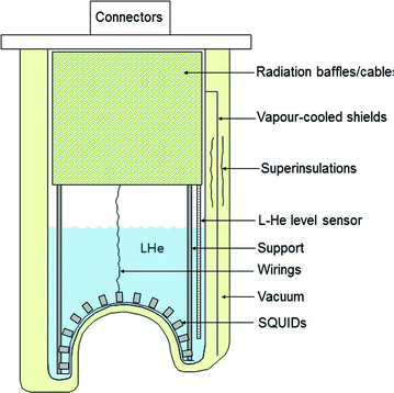

Fig. 9
Schematic structure of a helmet-shape liquid-He dewar
5 Magnetically Shielded Room
Depending on the noise conditions of the MEG site, an optimum combination of magnetically shielded room (MSR) and pickup coil is needed. In rural or magnetically quiet sites, the requirement for MSR is lowered. In a usual urban hospital or laboratory environment, reliable reduction of environmental noise is a key step for successful acquisition of MEG signals. The most effective and reliable method of reducing environmental noise is magnetic shielding (Nowak 1998; Kelhä et al. 1982). Typical environmental noise spectrum in an urban site is shown in Fig. 10. In an ordinary laboratory environment, low-frequency drift of the earth’s magnetic field is in the range of 100 ~ 1,000 nT, with variation frequency of about 0.1 Hz. Main sources of this low-frequency drift are operation (DC power supplied or movement) of subway (tram), public transportation and elevators, etc. By using high-pass filtering, this low-frequency drift does not affect the signal quality of MEG. But, if this drift is too large, the dynamic range of FLL could be reached, resulting in saturation of the FLL output.
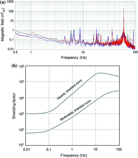

Fig. 10
Environmental noise and shielding factor of MSR. a Typical noise spectra of environmental noise. b Shielding factors as a function of frequency in moderately and heavily shielded room, respectively, used for MEG measurements
The amplitude of power line noise is in the range of 10 ~ 100 nT. Use of a notch filter can reduce the noise peak at power line frequency, at the expense of phase distortion near the elimination frequency. Some subways use a power system generating strong 16.67 Hz noise peak (sub-harmonic of 50 Hz).
Mechanical vibrations of the building, MSR, gantry, and vibration of the sensor insert inside the boiling liquid He dewar, etc., generate noise peaks in the frequency range of 5 ~ 20 Hz, which overlaps with the frequency band of MEG signals.
The MSR uses a combination of ferromagnetic shielding and eddy-current shielding. For ferromagnetic shielding, high-permeability Ni-alloy, called Mumetal or Permalloy, is used. Since the permeability of Ni-alloy is sensitive to stress, care should be taken in handling the material, and the material has to be hydrogen-annealed before assembling. The magnitude of residual DC fields inside common MSRs for MEG measurements are about 10 nT. This DC field level increases with time due to accumulation of stress or gradual magnetization of the soft ferromagnetic material. Thus, regular degaussing is needed to reduce the DC field, by applying a magnetic field to the ferromagnetic material with a field intensity much larger than the coercive force of the ferromagnetic material.
If the shielded room was assumed to be a cubic structure of side length L, the shielding factors of the ferromagnetic material is
 where μ r and t are the relative permeability and thickness of the magnetic layer, respectively. With a single layer, there is limitation in providing sufficient shielding factor. Thus, a multiple-layer structure is preferred, with separation between the layers.

In a 2-layer cubic structure, the shielding factor is
 where S 1 (L 1 ) and S 2 (L 2 ) are the shielding factor (side length) of the inner and outer layer, respectively. Typically, the separation between inner and outer layer is about 20 cm, and then the term S 1 S 2 {1-(L 1 /L 2 )3} dominates in the above equation. In 3-layer structure, even high shielding factors can be obtained,
 where S 1 (L 1 ), S 2 (L 2 ) and S 3 (L 3 ) are the shielding factor (side length) of the inner, middle and outer layer, respectively.


When the drift of the DC field is large, for example, at a measurement site near the subway, expensive ferromagnetic shielding alone does not provide sufficient shielding effect at low frequency, and an active compensation method is needed. For eddy-current shielding, effective at a frequency above 1 Hz, high-electrical-conductivity aluminum or copper plates are used (Erné 1983). Since electric conductors generate thermal magnetic noise, the inner-most part of the MSR has a ferromagnetic layer to shield the eddy-current noise from the conductive layer.
In eddy current shielding, an important parameter is skin depth δ


Stay updated, free articles. Join our Telegram channel

Full access? Get Clinical Tree


