Great Vessels


Great Vessels


Monica Epelman

Pilar Garcia-Pena

Eric J. Chong Barboza

Magdalena Gormsen

Fatma Hamza Makame

Edward Y. Lee


INTRODUCTION

Congenital and acquired thoracic vascular abnormalities involve the thoracic aorta and branch arteries, pulmonary arteries, thoracic systemic veins, and pulmonary veins. Imaging evaluation of these vascular abnormalities typically requires a combination of radiographs, ultrasound (echocardiography), computed tomography angiography (CTA), magnetic resonance imaging (MRI), magnetic resonance angiography (MRA), and catheter angiography (CA). In recent years, technological advances in multidetector-row computed tomography (MDCT) and MRI have greatly advanced the noninvasive diagnosis of these vascular anomalies in the pediatric population. The use of multiplanar (2D) and 3D visualization techniques in both aforementioned modalities provides comprehensive multiprojectional anatomical displays for interactive interpretation, treatment planning, and postoperative and postendovascular evaluation.1,2,3,4,5,6

Clear knowledge and understanding of a cost-effective approach and the appropriate utilization of the available imaging modalities are required in today’s clinical environment. The approach should be based on the type of underlying vascular abnormality, the inherent advantages and limitations of each imaging modality, and the overall performance of each imaging modality. In this chapter, up-to-date imaging techniques for evaluating the great vessels in infants and children are presented, and normal anatomy is reviewed. In addition, commonly encountered congenital and acquired thoracic vascular abnormalities are discussed with reference to clinical features, characteristic imaging findings, and treatment approaches.


IMAGING TECHNIQUES


Radiography

Chest radiography is readily available and provides a rapid and inexpensive means of obtaining initial diagnostic information in infants and children with clinically suspected thoracic vascular abnormalities. The chest radiograph provides valuable information concerning the structure and function of the cardiovascular system by permitting assessment of the size and extent of pulmonary vascularization as well as the size of the cardiac chambers. Although a chest radiograph is rarely sufficient to make a specific underlying cardiovascular diagnosis, for a small amount of radiation exposure (0.02 to 0.04 mSv), it may guide early treatment and subsequent advanced imaging and also serve as a baseline in certain conditions.

Chest radiographic examination usually consists of frontal and lateral views of the chest. In the case of neonates, chest radiographs are typically combined with an abdominal-pelvic radiograph, a so-called babygram, in order to facilitate the confirmation of appropriate positioning for all support devices including lines and tubes placed during initial evaluation. Subsequent chest radiographs should extend to at least the midabdomen, with or without the pelvis, depending upon the type of device, to account for variable degrees of inspiration. Such radiographs are obtained at the discretion of the medical team not only to permit the assessment of cardiovascular status but also especially to allow the evaluation of support devices, as malpositioned devices can lead to iatrogenic complications. In addition, the course of the support devices can offer clues to the individual patient’s underlying vascular
anatomy and provide a basis for the evaluation of congenital vascular abnormalities (Table 10.1).


TABLE 10.1 Abnormal Course of Support Devices Suggesting Vascular Anomalies or Congenital Heart Disease


Device


Abnormal Course


Endotracheal tube


If deviated leftward, may suggest a right aortic arch


Umbilical venous line


If ascends to the left of the spine, may suggest a left-sided or a double IVC May be seen in heterotaxy


Umbilical arterial line


If ascends to the chest on the right, may suggest a right aortic arch


If ascends to the chest on the left, but crosses to the right of the spine, may suggest a right aortic arch with a circumflex aorta


PICC line


If descends along the left mediastinum → left-sided SVC to coronary sinus


If ascends to the left of the spine → left-sided or a double IVC


Enteric tube


If terminates in the right upper quadrant → right-sided stomach → heterotaxy


PICC, peripherally inserted central catheter; IVC, inferior vena cava; SVC, superior vena cava.


Ultrasound and Echocardiography

Ultrasound (US) and transthoracic echocardiography (ECHO) are usually the next diagnostic modalities employed in the assessment of infants and children with clinically suspected of having thoracic vascular abnormalities. Vascular US is used to visualize the peripheral vascular system, and ECHO is used for the heart, coronary arteries, pulmonary vasculature, thoracic aorta, and intrathoracic systemic veins. US and ECHO have advantages over other imaging modalities because they permit the noninvasive evaluation of morphology, function, and flow without exposure to radiation or potentially nephrotoxic contrast medium. Real-time gray-scale US images and cine loops are acquired in multiple projections to the heart, aorta, central pulmonary arteries and veins, and central intrathoracic systemic veins to depict various segments of the cardiac anatomy and vascular branches. In addition, flow characteristics such as direction and velocity can be determined by Doppler. However, US and ECHO are limited by acoustic impedance, operator skill, and ability to visualize peripheral vascular segments, including those of the pulmonary arteries, pulmonary veins, and supra-aortic branch arteries.3,4,5


Computed Tomography

Nowadays, the evaluation of great vessel abnormalities can usually be performed with MDCT using CTA protocol without sedation and electrocardiographic gating. Because of the inherent radiation risk, CT should be judiciously used in pediatric patients. CT is typically indicated for evaluation of mediastinal vascular abnormality in infants and children when (1) there is a high sedation or general anesthesia risk; (2) coas-sessment of noncardiovascular structures, especially the airway and lungs, is required; (3) emergent imaging is necessary; and (4) higher spatial resolution is needed. Other advantages of CT include wide clinical availability and short examination times.

With the latest generation CT scanners, acquisition time <2 seconds is feasible for mediastinal vascular imaging in pediatric patients. On the other hand, a typical MRI examination is currently acquired over 30 to 45 minutes. Obtaining selected MRI sequences may potentially decrease the total examination time to 10 to 15 minutes, but in most instances, this does not entirely obviate the need for sedation or general anesthesia in infants and young children who cannot follow breathing instruction.

Thoughtful patient preparation before CT imaging can lead to high-quality CT data set for accurately assessing great vessels, which in turn can result in optimal patient care. In order to optimize photon delivery and minimize the adverse effect of noise, the targeted region needs to be isocentered in the gantry. All external metallic objects and support devices with metallic components (e.g., weighted feeding tubes) should be removed, if possible, from the region to be scanned. This is because the presence of radiodense material may result in streak artifacts and can aggravate the effects of noise when low-dose parameters are used.4 Similarly, the upper extremities are raised above the head and out of the field of view when performing chest CT, whereas they are placed at the patient’s side for head and neck CT studies.

Because of their inherent dependence upon radiation, CT protocols in pediatric patients should strive for only one core series (i.e., a single-phase angiographic scan). Such CT examination is typically obtained using the lowest possible voltage (80 kVp is usually sufficient for most pediatric patients under 60 kg) and with weight-based low-dose milliamperage following as low as reasonably achievable (ALARA) principle. In addition, at lower tube voltages (80 kVp), the use of iodinated contrast material is more efficient and yields higher attenuation of the vascular structures scanned because 80 kVp is closer to the k-edge of iodine (33.2 keV).7,8

For mediastinal vascular imaging with CTA, highly concentrated iodine contrast medium (300 to 370 mg I/mL) is administered according to weight (2 mL/kg, not to exceed 5 mL/kg or a total of 100 mL), at the highest weight-based injection rate possible via a pressure-limiting power injector (e.g., a pressure limit set to 200 to 250 psi).3,4,5 The injection rate currently used varies according to the patient’s weight
and IV access. For example, the injection rate of ˜1.0 mL/s can be used in infants. For adult-sized older children, the contrast can be injected at 3 to 5 mL/s. The antecubital location is the preferred access site for the larger vein size needed to accommodate high flow rates of IV contrast administration for CTA. In neonates and young infants, a forearm, hand, or foot vein may also be considered. In such cases, the use of a power injectable, peripherally inserted central catheter is a more desirable and safer option.4 On the basis of hemodynamic and anatomic data, the injection of IV contrast medium should be performed into the right upper extremity vein in order to limit streak artifacts from the dense contrast across the aortic arch, which can occur when the left upper extremity vein is used9 (Table 10.2). Initially, the test injection should be performed using peripheral IV access with saline with a flow rate similar to that planned for the contrast medium for CTA. If the test injection is uneventful, the contrast injection, followed by a saline chase to clear the venous inflow and optimize the volume of contrast medium that reaches the target region, can be subsequently obtained.


TABLE 10.2 Recommended Intravenous Catheter Sites in Relation to Anatomy


Type of Study


Preferred IV Catheter Site


Second Choice


Other Possible Location


Chest CTA/MRA with left aortic arch


Right AC


Foot


Last resource: left AC


Chest CTA/MRA with right aortic arch


Left AC


Foot


Last resource: right AC


Abdomen/pelvis CTA/MRA


Right or left AC


Last resource: foot


Right upper extremity CTA/MRA


Left AC


Foot


Last resource: right AC


Left upper extremity CTA/MRA


Right AC


Foot


Last resource: left AC


Both upper extremities CTA/MRA


Foot


Bilateral lower extremities CTA/MRA


Right or left AC


AC, antecubital; IV, intravenous.


CT imaging using automated bolus tracking should be considered because this method permits the use of a lower total amount of contrast agent and optimizes the accurate timing of the CT scanning.3,10,11 A region of interest (ROI) is placed in the vessel to be evaluated, and the CT imaging is triggered automatically when a predefined enhancement threshold (e.g., 90 to 150 HU) is achieved. In general, the minimum amount of coverage and the shortest possible scan times (fast gantry rotation times, high pitch, and volumetric CT techniques) should be used. If possible, coverage should be tailored to the specific clinical question, and radiosensitive organs such as the thyroid should be avoided or limited. CTA for the evaluation of mediastinal vascular abnormality is typically obtained under suspended respiration or during quiet breathing.

Once axial CT data set is obtained, they can be reconstructed into 3- or 5-mm-thick axial CT images for routine viewing and into at least 1.5 mm axial CT images with 50% overlap for reconstructions and to maximize 3D displays3,4,5,11 (Table 10.3). The use of 3D visualization techniques provides comprehensive multiprojectional anatomical displays of often complex mediastinal vascular abnormalities for interactive interpretation, treatment planning, and postoperative and postendovascular evaluation.1,2,3,4,5 Volume-rendered (VR) and maximum intensity projection (MIP) images are currently available and clinically helpful for (1) depiction of the spatial relationship between the vessels in question and the adjacent structures, (2) grading of vascular stenosis and extent, and (3) improved delivery of the findings obtained by imaging to the referring clinicians and families.1 The use of interactive 3D workstations not only facilitates the evaluation of the vascular structures, which are better depicted in the z-axis, but also assists in overcoming the noise that may occur with the use of low-dose protocols.4,5,6


Magnetic Resonance Imaging

MRI is an increasingly utilized imaging modality for evaluating the great vessels, particularly in the pediatric population. However, it is rarely used as a first-line imaging modality. MRI typically complements US or ECHO as a noninvasive alternative to conventional CA. When used to evaluate more central vascular structures such as great vessels, three main types of MRI techniques are currently available that include (1) ECG-gated “black-blood” MR imaging, (2) static and cine “white-blood” MR imaging, and (3) a 3D contrast-enhanced angiographic MR imaging.

Black-blood MR imaging refers to the low signal exhibited by cardiovascular structures. It is used primarily to delineate anatomy and morphology and to visualize spatial relationships, particularly those of vascular structures and the adjacent central airway.5,12,13 In the past, spin-echo sequences were used for black-blood imaging; today, these techniques have been largely supplanted by fast spin-echo (FSE) and turbo spin-echo (TSE) techniques.14 These MRI sequences are ECG gated at end diastole and may be obtained with or without double inversion recovery techniques in order to null the signal from blood. They also may be obtained in any desired plane, including the sagittal oblique or “candy cane” view. Care should be taken with slow-flowing blood and when gadolinium is present because these conditions may interfere
with the nulling of flowing blood and may appear bright on the sequence, potentially resulting in artifacts that may lead to misinterpretation. For this reason, gadolinium should be administered only after black-blood imaging has been performed.14 T1-weighted gradient echo sequences performed before and after contrast administration are usually used instead of black-blood MR images for the assessment of vessel wall thickening in cases of vasculitis.15


TABLE 10.3 Cardiovascular Advanced Visualization Techniques


Display


Principle Use


Advantages


Disadvantages


MPR


2D


  • Structural detail


  • Quantitative analysis


  • “Slice” through data set in coronal, sagittal, and oblique projections


  • Real-time multiplanar interrogation


  • Simplify image interpretation


  • Limited spatial perception


CPR


2D


  • Structural detail


  • Centerline display


  • Simplify MPR


  • Single anatomical display


  • Longitudinal cross-sectional anatomical display


  • Operator dependent


Ray-Sum


2D


  • Structural overview


  • “Slice” through data set in axial, coronal, sagittal, and oblique projections


  • Real-time multiplanar interrogation


  • Radiograph-like display


  • Loss of structural detail with increased slab thickness


MIP


2D


  • Structural overview


  • Angiographic display


  • “Slice” through data set in axial, coronal, sagittal, and oblique projections


  • Real-time multiplanar interrogation


  • Improved depiction


  • Small caliber vessels


  • Poorly enhanced vessels


  • Communicate findings


  • Anatomical overlap (vessels, bone, viscera) with increased slab thickness


  • Visualization degraded by high-density structures (i.e., bone, calcium, stents, coils)


  • Loss of structural detail with increased slab thickness


  • Limited grading of stent lumens


MinIP


2D


  • Structural Overview


  • Airway


  • Air trapping in the lung


  • Soft tissue air


  • “Slice” through data set in axial, coronal, sagittal, and oblique projections


  • Real-time multiplanar interrogation


  • Depict low-density structures


  • Communicate findings


  • Anatomical overlap


  • Loss of structural detail with increased slab thickness


VR


3D


  • Structural overview


  • Angiographic display


  • “Slice” through data set in axial, coronal, sagittal, and oblique projections


  • Real-time multiplanar interrogation


  • Depict structural relationships


  • Accurate spatial perception


  • Communicate findings


  • Dependent upon opacity-transfer function


  • Anatomical overlap


  • Loss of structural detail with increased slab thickness


2D, two dimensional; 3D, three dimensional; MPR, multiplanar reformation; CPR, curved planar reformation; MIP, maximum intensity projection; MinIP, minimum intensity projection; VR, volume rendered.


Reprinted from Hellinger JC, Pena A, Poon M, et al. Pediatric computed tomographic angiography: imaging the cardiovascular system gently. Radiol Clin North Am. 2010;48(2):439-467, with permission. Ref. 4.


Bright-blood or white-blood MR imaging may consist of static and/or cine images. Static white-blood images are generally obtained with the steady-state free precession (SSFP) technique; a full stack of the entire chest can be acquired in <30 seconds, providing a useful adjunct to the more time-consuming acquisition of a black-blood MR imaging sequence for anatomic depiction. Cine white-blood MR imaging is typically used to evaluate cardiac function and is usually obtained either with gradient-echo sequences or with a balanced-SSFP pulse sequence. These MRI sequences provide cine images that permit visualization of cardiac or valvular motion in multiple frames over the entire cardiac cycle, allowing assessment of cardiac function and calculation of ventricular volumes. The SSFP pulse sequence demonstrates high signal-to-noise and high contrast-to-noise ratios between the blood pool and myocardial interface.11,12,13,14,16


Angiographic techniques include time-of-flight MRA, multiphase (arterial and venous) 3D T1-weighted contrast-enhanced MRA, and time-resolved MRA. Contrast-enhanced acquisitions are often conducted in the coronal plane, depending on the required anatomical coverage and breath-hold duration. The use of time-resolved MRA permits the depiction of reliable first-pass imaging that is independent of the timing of contrast injection and acquisition, resulting in clear depiction of dextro and levo phases and providing insight into the hemodynamics of the disease process and the assessment of collateral circulation. Multiplanar reformatting, maximum-intensity projection, volume rendering, and virtual endoscopy are useful adjuncts for enhancing interpretation5,6,12,13,16,17,18 (Table 10.3).

Phase-contrast imaging with velocity-encoded imaging is a useful adjunct to the acquisition of angiographic MR images. It is primarily used as a noninvasive method to accurately quantify velocity, flow, and related pressure gradients. Pulmonary blood flow (Qp) and systemic blood flow (Qs) may be assessed with this technique and used to calculate the pulmonary-to-systemic flow ratio (Qp:Qs) and to determine the shunt fraction. A Qp:Qs >1.5 usually indicates a significant left-to-right shunt that may require intervention.5,19


Nuclear Medicine

Nuclear medicine studies involving the pediatric thorax are primarily used to evaluate myocardial perfusion and viability in adult patients. Lung ventilation/perfusion imaging, which is at times used for the diagnosis of pulmonary embolism in adult, is mainly employed for quantification of differential and regional lung perfusion in congenital heart disease in pediatric patients. Right-to-left shunts may be demonstrated during the course of a perfusion scan by showing accumulation of the radiotracer within capillary beds of other organs, typically the brain and kidneys.20


Catheter Angiography

Catheter angiography remains the reference standard for vascular imaging in both pediatric and adult patients. However, it is invasive and exposes the pediatric patient to radiation and to the nephrotoxic effects of iodinated contrast media. Catheter angiography also typically requires the use of sedation or general anesthesia. In today’s clinical practice, Catheter angiography is primarily used for interventions. In rare instances, it is used as a problem-solving tool for issues related to morphology, flow, or function that cannot be fully answered by the other noninvasive imaging modalities.4,5


NORMAL ANATOMY


Aorta

The normal thoracic aorta can be divided into four major segments: the aortic root, the ascending aorta, the aortic arch, and the descending aorta. The aortic root is the segment of the aorta that originates from the left ventricle. The aortic root includes the aortic valve annulus, the aortic valve cusps, and the sinuses of Valsalva, including the right, left, and noncoronary sinuses, which serve as attachments for the valve leaflets and house the coronary arteries ostia. The ascending aorta extends from the sinotubular junction to the first branch of the aortic arch, typically the brachiocephalic or innominate artery. In normal individuals, the sinotubular junction is characteristically distinguished by a sharp waist to which the aortic leaflets attach. The aortic arch extends from the origin of the brachiocephalic artery to the insertion of the ductus or ligamentum arteriosum. The aortic arch gives origin to the major head and neck arteries. From anterior to posterior, these typically consist of the brachiocephalic, left common carotid, and left subclavian arteries. Common normal variants include a bovine arch consisting of a common origin of the brachiocephalic artery and the left common carotid artery and a direct origin of the left vertebral artery off the aortic arch between the origins of the left common carotid and left subclavian arteries. The descending aorta begins at the aortic isthmus, which is marked by the location of the ductus or ligamentum arteriosum.21 The descending aorta is further subdivided into thoracic and abdominal portions at the aortic hiatus.15,22,23

Standardized, reproducible aortic landmarks for measurement were published in 2010 in an ACCF/AHA guideline.15 The published guideline notes that external diameter measurements should be made perpendicular to the longitudinal or flow axis of the vessel (Fig. 10.1). It should be noted that, in the cardiology literature, the aortic isthmus is considered only the point at which the ligamentum arteriosum inserts.15,21; however, several authors in the radiologic literature consider the aortic isthmus to represent the portion of the distal aortic arch that extends from the left subclavian artery to the insertion of the ligamentum arteriosum.22,24,25,26 In 2008, Kaiser et al.27 established normal values for thoracic aortic dimensions related to body growth in children and adolescents aged 2 to 20 years using images obtained by contrast-enhanced MR angiography. These authors provided an Excel file that permits the calculation of percentiles and z-scores and graphical display of the calculated values on the normative curves. These data are especially suitable for pediatric patients and may be utilized for the diagnosis, treatment planning, and follow-up of aortic abnormalities in the pediatric population. Given the lack of normative data obtained with contrast-enhanced MR angiography in neonates and young infants with body surface areas <0.5 m2, Madan and colleagues28 recommend the use of ECHO-based z-scores for this subset of patients.


Pulmonary Artery

The main pulmonary artery (MPA) originates during the 4th week of embryogenesis after the conotruncal division is formed. Originating from the right ventricular outflow tract, it transports deoxygenated blood to the lungs for oxygenation, a distinctive function of the pulmonary arteries. The MPA follows an intrapericardial direction coursing superiorly and posteriorly. The MPA then passes anteriorly and to the left of the
ascending aorta before giving origin to the right and left pulmonary arteries, which are derived from the sixth pharyngeal arch. The left pulmonary artery (LPA) is shorter and slightly smaller than the right pulmonary artery (RPA). The ductus or its remnant, the ligamentum arteriosum, courses posteriorly and superiorly to the undersurface of the aortic arch just distal to the origin of the left subclavian artery. The RPA and LPA travel along the bronchi down to the subsegmental level matching the adjacent bronchi in course and caliber.22,29,30,31


FIGURE 10.1 Normal aortic segments with standard landmarks for reporting aortic diameter. Locations: (1) sinuses of Valsalva; (2) sinotubular junction; (3) midascending aorta; (4) proximal aortic arch; (5) midaortic arch; (6) proximal descending thoracic aorta (begins at the isthmus); (7) middescending aorta; (8) aorta at diaphragmatic hiatus; (9) abdominal aorta at the celiac axis origin. (Based on Hiratzka LF, Bakris GL, Beckman JA, et al. 2010 ACCF/AHA/AATS/ACR/ASA/SCA/SCAI/SIR/STS/SVM guidelines for the diagnosis and management of patients with thoracic aortic disease: executive summary. A report of the American College of Cardiology Foundation/American Heart Association Task Force on Practice Guidelines, American Association for Thoracic Surgery, American College of Radiology, American Stroke Association, Society of Cardiovascular Anesthesiologists, Society for Cardiovascular Angiography and Interventions, Society of Interventional Radiology, Society of Thoracic Surgeons, and Society for Vascular Medicine. Catheter Cardiovasc Interv. 2010;76[2]:E43-E86. Ref. 15.)

The relationship of the pulmonary arteries to the central airway is important for the assessment of thoracic situs because there is good agreement between this relationship and atrial laterality, one of the most important factors in determining situs. The relationship between the pulmonary arteries and the central bronchi can be easily demonstrated on multiplanar (2D) and 3D reconstructions. Identification of the right eparterial bronchus, meaning that the first branch of the right mainstem bronchus is above the level of the RPA, and the left hyparterial bronchus, meaning that the first branch of the left mainstem bronchus is below the level of the LPA, is considered predictive of thoracic situs solitus.29


Pulmonary Veins

In most instances, there are four individual pulmonary veins, two for each lung. However, there is substantial variation in the number and branching pattern of the pulmonary venous drainage, with variation on the right considerably greater than that on the left. The most common variation, which is seen in ˜25% of cases, is the presence of an additional third pulmonary vein on the right side that independently drains the right middle lobe.32,33,34


Superior Vena Cava

The superior vena cava (SVC) serves as the major draining route for the veins of the head and neck and the bilateral upper extremities. The SVC is formed by the confluence of the right and left brachiocephalic veins. The SVC courses caudally and drains into the morphologic right atrium.33,34,35,36


Inferior Vena Cava

The suprahepatic inferior vena cava (IVC) is a short intrathoracic portion of the IVC that drains the lower half of the body into the right atrium. It crosses the diaphragm at the level of T8 after receiving the hepatic veins. Imaging confirmation of IVC drainage into the right atrium is an important clue in the determination of atrial situs solitus because it is unusual for the IVC to drain elsewhere.33,34


SPECTRUM OF GREAT VESSEL ABNORMALITIES


Congenital Great Vascular Anomalies


Aorta


Cervical Aortic Arch

Cervical aortic arch (CAA) is a rare vascular anomaly in which the aortic arch is in a supraclavicular location (Fig. 10.2). Clinically, it may present as a pulsatile lesion in the ipsilateral supraclavicular fossa. This vascular anomaly is believed to be the result of persistence of the embryonic third arch with regression of the expected fourth arch. CAA has been described in association with chromosome 22q 11 deletion.5,22,37


Left Aortic Arch with an Aberrant Right Subclavian Artery

A left aortic arch with an aberrant right subclavian artery is the most common type of aortic arch anomaly. In this vascular anomaly, the aortic arch gives rise, in sequence, to the
right common carotid artery, the left common carotid artery, the left subclavian artery, and the aberrant right subclavian artery, which takes a retroesophageal course. This vascular anomaly does not form a vascular ring because the trachea and esophagus are not entirely surrounded by vessels and/or ligaments. In the older literature, the presence of this variant was reported to result in so-called dysphagia lusoria in elderly patients. In these cases, the aberrant right subclavian artery is smooth in its contours, nearly equal in caliber throughout its intrathoracic course and tapers gradually37,38,39 (Fig. 10.3).


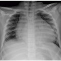
FIGURE 10.2 Cervical aortic arch in a 3-year-old girl who presented with a pulsatile left upper chest mass. A: Frontal chest radiograph shows a superior mediastinal lesion (arrows). B: Axial enhanced CT image demonstrates a left aortic arch (arrow) which is located in a supraclavicular region.


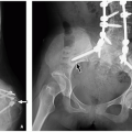
FIGURE 10.3 Left aortic arch with an aberrant right subclavian artery in a 2-month-old boy who presented with intermittent stridor. A: Lateral view of esophagogram shows mass effect (arrow) upon the posterior aspect of the barium containing esophagus. B: 3D volume-rendered CT image demonstrates an aberrant right subclavian artery (arrow), which is smooth in caliber and without evidence of a Kommerell diverticulum or airway compression. However, the compression on the esophagus (E) is again seen.


Vascular Rings

Vascular rings are a spectrum of congenital mediastinal vascular anomalies resulting from abnormal development of the embryonic aortic arches. As a result of these vascular anomalies, the trachea and esophagus are completely surrounded by vessels or their atretic portions, potentially resulting in airway or esophageal compression.5,38,39,40,41,42,43 The vessels conforming the vascular ring may include the aortic arch or arches, aortic arch branch vessels, pulmonary branch arteries, and the ductus arteriosus or the ligamentum arteriosum.38,39


Affected pediatric patients may be asymptomatic, and the anomaly may be incidentally discovered in adulthood. Alternatively, the resulting airway compression may produce substantial respiratory symptoms such as a distinctive stridor worsening with feedings, cyanotic episodes, and even respiratory arrest, particularly in neonates and young infants.38,40,41,43,44,45,46 Aortic arch anomalies have been reported in association with chromosome 22q11 deletion.5,37 Moreover, chromosome 22q11 deletion is found in ˜25% of patients with aortic arch anomalies who lack associated intracardiac defects.44

In the past, barium esophagography used to be the primary imaging modality for the evaluation of vascular rings during the early 1930s. However, CA became the reference standard in the 1960s. Currently, CT and MRI have largely replaced the aforementioned modalities given their higher sensitivity (approaching 100%) for the diagnosis of vascular rings in noninvasive manner.43

Symptomatic vascular rings are currently surgically managed to reduce compression of the airway and esophagus in the pediatric population (Table 10.4).


Double Aortic Arch with Variants

Double aortic arch (DAA) is the result of persistence of both the right and left embryonic fourth arches (Fig. 10.4). It is the most common form of symptomatic vascular ring. DAA is seldom associated with congenital heart disease; if present, the congenital disease is usually tetralogy of Fallot.

In the majority of DAA, both arches remain patent; however, in some cases, an atretic segment may be present in either arch. The atretic segment is more typically seen in the left arch and is characteristically located following the take-off of the left subclavian artery.1,5,38,39 Therefore, in the majority of cases, the right arch is dominant. Typically, the right arch is more superiorly located than the left arch, as is best seen on coronal cross-sectional images. In these instances, the descending aorta is more frequently seen on the left side.38 Less frequently, the two arches are codominant and equivalent in size or the right arch is atretic and the left arch is dominant. When both arches are patent and similar in size, each arch shows relatively symmetric origins of each of the four major supraaortic vessels (right and left carotid and subclavian arteries) from the respective arch, constituting an important imaging clue (four-vessel sign) in the diagnosis of this mediastinal vascular anomaly. However, in instances in which the right arch is dominant, the branching pattern may be indistinguishable from those of the right aortic arch with mirror image branching. In this situation, the only clue for diagnosis would be a left-sided descending aorta on the side opposite that of the arch5,38,39 (Figs. 10.5 and 10.6).


TABLE 10.4 Surgical Management of Symptomatic Vascular Rings


Right aortic arch with an aberrant left subclavian artery


Surgical division of left ligamentum arteriosum


Left thoracotomy approach


Double aortic arch


Surgical division of the smaller arch and the ligamentum (if present)


Thoracotomy ipsilateral to the smaller arch


Circumflex left aortic arch


Surgical division of right ligamentum arteriosum


Right or midline thoracotomy approach


FIGURE 10.4 Double aortic arch. Ao, ascending aorta; LCCA, left common carotid artery; LSA, left subclavian artery; PA, pulmonary artery; RCCA, right common carotid artery; RSA, right subclavian artery.

Surgical division of the underlying vascular ring is current management of choice for symptomatic pediatric patients with DAA. When considering surgical division, it should be recognized that a ligamentum arteriosum or, in some cases, a patent ductus arteriosus may be present, which should be also divided in addition to one of the arches. If not, the ligamentum may still form a vascular ring once the arches are divided, without amelioration of the symptoms.38,39


Circumflex Left Aortic Arch

In this rare aortic vascular anomaly, the aortic arch is left sided and the aorta loops around the trachea, coursing posterior to the esophagus to the right side of the spine and resulting in a proximal right descending aorta opposite the side of the arch. A right-sided ligamentum or a right-sided ductus typically completes the vascular ring. Therefore, unlike most instances, a right thoracotomy approach is needed in order to divide the vascular ring although a midline approach may also be utilized. This aortic vascular anomaly may occur in association with an aberrant right subclavian artery. In this situation, the aberrant subclavian artery is not retroesophageal in its course despite the fact that it arises from the descending aorta as the last arch vessel as it passes from its horizontal to its more nearly vertical course.5,37


Right Aortic Arch with Variants

Three main types of right aortic arch anomalies may be seen in association with vascular rings:


  • Right aortic arch with an aberrant left subclavian artery off a Kommerell diverticulum


  • Right aortic arch with left descending aorta (right circumflex aortic arch) (Fig. 10.7)


    FIGURE 10.5 Double aortic arch with a dominant right arch and a smaller left arch with an atretic segment in a 2-year-old girl who presented with a history of recurrent pulmonary infections and an abnormality on chest radiograph. A: Frontal chest radiograph shows mild deviation of the trachea (asterisk) to the left with an indentation (arrow) on the right lateral wall of the trachea suggesting a right sided aortic arch. B: Lateral esophagogram image demonstrates a posterior indentation (arrow) with narrowing of the esophagus. C: Posterior view of 3D volume-rendered CT image shows a double aortic arch with a dominant right arch (RA) and a smaller left arch with an atretic segment (arrow). (DA, descending aorta.) 3D volume-rendered CT images facilitate evaluation of arch dominance and location.


    FIGURE 10.6 Double aortic arch in an 18-month-old boy who presented with progressively worsening stridor. A: Axial enhanced CT image shows symmetric origins of the four arch vessels (white arrows), also known as “four-vessel” sign, arising separately from the two aortic arches. (RCCA, right common carotid artery; RSCA, right subclavian artery; LCCA, left common carotid artery; LSCA, left subclavian artery). Both aortic arches are nearly equal in size and encircle the narrowed trachea ( yellow arrow). B: Superior view of 3D volume-rendered CT image demonstrates the characteristic vascular anatomy of a double aortic arch to better advantage. In this instance, the right (R) and left (L) aortic arches have relative codominance, forming a complete vascular ring. C: 3D volume-rendered CT image shows the marked tracheal compression (arrows) at the level of the double aortic arch.


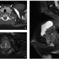
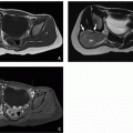
    FIGURE 10.7 A circumflex aortic arch in a 5-year-old boy who presented with dysphagia and an abnormal esophageal impression on barium swallow study. Axial double inversion recovery MR images at the level of the right-sided aortic arch (A) and more inferiorly (B) show a right aortic arch (RA) and the descending portion (DA) of the circumflex aorta located to the left of the spine, indicating that there is a vascular ring. T, trachea. C: 3D volume-rendered CT image shows the circumflex aorta (arrow) coursing from right to left.


    FIGURE 10.8 Right aortic arch with an aberrant left subclavian artery. Asc AO, ascending aorta; LCA, left common carotid artery; LPA, left pulmonary artery; LSCA, left subclavian artery; MPA, main pulmonary artery; RCA, right common carotid artery; RSCA, right subclavian artery.


  • Right aortic arch with mirror-image branching and a left retroesophageal ductus arteriosus or ligamentum arteriosum (Fig. 10.8)


FIGURE 10.9 Right aortic arch with an aberrant left subclavian artery off a Kommerell diverticulum in a 5-month-old girl who presented with worsening stridor. A: Axial enhanced CT image shows a right aortic arch (RA) with a Kommerell diverticulum (arrow). Trachea (T) compression is also seen. B: 3D volume-rendered CT image demonstrates an aberrant origin of the left subclavian artery (arrow) off a Kommerell diverticulum (asterisk). The Kommerell diverticulum (asterisk) is larger in caliber than the subclavian artery (arrow) because it represents a remnant of the ductus arteriosus that once carried much of the systemic blood flow during fetal life. The atretic portion of the ligamentum arteriosum completes the ring, but is not visible with current CT techniques. RA, right aortic arch. C: Coronal external volume-rendered CT image of the airways and lungs shows the narrowing (arrow) of the trachea because of underlying vascular ring.


Right Aortic Arch with an Aberrant Left Subclavian Artery Off a Kommerell Diverticulum

This is the second most common type of symptomatic vascular ring after the DAA in the pediatric population (Fig. 10.9). However, it is often asymptomatic and incidentally discovered. In sequential order, the branching pattern of this aortic arch anomaly consists of the left common carotid artery, the right common carotid artery, the right subclavian artery, and the aberrant left subclavian artery. The latter originates from a diverticulum of Kommerell, which is the result of the embryonic origin of the left aberrant subclavian artery off the patent ductus arteriosus. Therefore, as a rule of thumb, it is important to recognize that a diverticulum of Kommerell is typically associated with the presence of an ipsilateral ligamentum arteriosum that is not visible with contemporary imaging techniques. Such ligamentum arteriosum connects the pulmonary artery to the aortic diverticulum, thereby constituting a vascular ring.


Right Aortic Arch with Left Descending Aorta (Right Circumflex Aortic Arch)

In this aortic vascular anomaly, the aortic arch is right sided, whereas the descending aorta is left sided (Figs 10.7 and 10.10). A left ductus or ligamentum arteriosum completes the vascular ring. This is the third most common type of vascular ring.37,38,39 The right-sided aortic arch courses posterior to the trachea and esophagus in a so-called right circumflex aortic arch configuration and then makes an acute turn. Inferiorly, the descending aorta courses along the left side of the spine. This is unlike cases of right aortic arch in which the descending aorta, after coursing over the right mainstem bronchus, gradually descends for some distance on the right and then
progressively courses into the left before reaching the aortic hiatus.


FIGURE 10.10 Right aortic arch with left descending aorta (right circumflex aortic arch) in a 3-month-old boy who presented with increasing respiratory distress. Posterior view (A) and cranial view (B) of 3D volume-rendered CT images show a right-sided aortic arch (RA). There is also a prominent, patent ductus arteriosus (PDA) completing the vascular ring. Note that the aberrant left subclavian artery (LSCA) originates from the PDA. (RSCA, right subclavian artery.)


Right Aortic Arch with Mirror-Image Branching and A Left Retroesophageal Ductus Arteriosus or Ligamentum Arteriosum

A right aortic arch with mirror image branching and a left retroesophageal ductus arteriosus or ligamentum arteriosum is a rare aortic vascular anomaly. It is the only type of right aortic arch with mirror-image branching that constitutes a vascular ring (Fig. 10.11). The branching sequence is as follows: brachiocephalic artery (left common carotid and left subclavian arteries) form the first branch, followed by the right common carotid and the right subclavian arteries. A left-sided patent ductus arteriosus or a ligamentum arteriosum off a prominent aortic diverticulum completes the vascular ring. This aortic vascular anomaly should not be confused with right aortic arch with mirror image branching (Fig. 10.11), a condition that is characteristically associated with patients with tetralogy of Fallot. In these instances, the ductus or ligamentum is usually right sided and does not form a complete vascular ring.


Pulmonary Artery


Pulmonary Agenesis, Aplasia, and Hypoplasia

Pulmonary underdevelopment may be classified into three major categories: (1) pulmonary agenesis characterized by absence of the lung, bronchus, and pulmonary artery (Fig. 10.12); (2) pulmonary aplasia defined by the presence of a rudimentary bronchus as well as absent lung and pulmonary artery; and (3) pulmonary hypoplasia consisting of a rudimentary bronchial tree and pulmonary artery with a variable amount of lung parenchyma.47,48,49,50 Pulmonary agenesis may be isolated or may be part of a syndrome such as chromosome 22q11 deletion and Goldenhar. It also may be part of a syndrome such as VACTERL (vertebral defects, anal atresia, cardiac defects, tracheo-esophageal fistula, renal anomalies, and limb abnormalities) association.49,51

The underlying etiology of pulmonary agenesis or aplasia remains uncertain, and genetic, teratogenic, and mechanical factors may all contribute. Given the common association between lung agenesis and ipsilateral radial ray defects or hemifacial microsomia, it has been postulated that in some cases, it may result from maldevelopment of or abnormal blood supply to the first and second embryonic arches.52 On the other end of the spectrum, often no identifiable cause can be found for lung hypoplasia.47

On frontal chest radiographs, the affected hemithorax is usually small and radiopaque, with ipsilateral mediastinal shift and hemidiaphragmatic elevation related to volume loss (Fig. 10.12A). The normal contralateral lung exhibits compensatory hyperinflation and herniation across the midline, manifested by a band of increased retrosternal lucency on lateral projections. Not infrequently, vertebral segmentation and rib anomalies may be observed.47,50 CT is useful in delineating the anatomy and spatial relationship between the
abnormal vasculature and adjacent airway. Furthermore, the multiplanar and 3D reformatted CT images may aid in differentiation between pulmonary agenesis, pulmonary aplasia, and severe pulmonary hypoplasia by better depicting the bronchial stump and/or rudimentary bronchial tree47,50,53 (Fig. 10.12).


FIGURE 10.11 Right aortic arch with mirror image branching in a 5-year-old boy who presented with abnormal chest radiograph obtained for evaluation of pneumonia. Axial white-blood (A) and coronal 3D volume-rendered (B) MR images show a right aortic arch (RA) with mirror image branching. First branch, innominate equivalent with a common trunk (straight arrow) for the left common carotid and left subclavian artery, followed by the right common carotid artery (curved arrow) and right subclavian artery (arrowhead) are seen.

The prognosis for pediatric patients with pulmonary agenesis, aplasia, or hypoplasia depends on the extent of lung underdevelopment and the type of coexisting malformation(s) present.47 The prognosis for pediatric patients with right-sided lung agenesis is poorer than that of patients with left-sided agenesis; this is attributable to the greater distortion of the airway and cardiovascular structures as well as a reported increased incidence of coexistent cardiovascular anomalies in the former.49 The most commonly reported associated anomalies involve the heart and the gastrointestinal system, followed in order of frequency by skeletal, vascular, craniofacial, and genitourinary anomalies.47,49,53,54


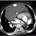
FIGURE 10.12 Pulmonary agenesis in a 15-year-old girl who presented with worsening asthma. A: Frontal scout CT image shows marked hyperinflation of the left lung that extends across the midline anteriorly and herniates toward the right. There is dextroposition of the heart into the right hemithorax. B: Coronal posterior view 3D volume-rendered CT image of the central airways and lungs demonstrates complete agenesis of the right bronchus and lung. A normal left mainstem bronchus (arrow) is seen. C: Axial 3D volume-rendered CT image also shows dextroposition of the heart and compensatory hyperexpansion of the left lung, particularly of the left upper lobe (asterisks), which herniates into the right hemithorax.

Management is currently aimed at improving respiratory status and symptoms related to the coexisting congenital malformations. It is recommended that regular immunizations
and flu vaccinations during the winter months should be given to affected children with substantial underlying lung deficiency. In infants under the age of 2, some authors advocate preventive care with palivizumab during the respiratory syncytial virus season.49 In rare instances, when the associated cardiovascular anomalies result in substantial airway compromise, surgery may be required.49,50


Pulmonary Artery Sling (Aberrant Left Pulmonary Artery)

Pulmonary artery sling (PAS) occurs as a result of an anomalous origin of the LPA from the posterior aspect of the RPA (Fig. 10.13). The anomalous LPA courses over the right mainstem bronchus and then from right to left between the trachea and the esophagus, reaching the left lung hilum. When it does, it forms a sling around the distal trachea5,43,47,50,55,56 (Figs. 10.14 and 10.15). This type of vascular ring is completed by a left ligamentum arteriosum connecting the MPA or RPA to the left descending aorta, resulting in a complete vascular ring that enfolds the trachea but spares the esophagus.5,47 It is postulated that PAS develops as a result of abnormal proximal left sixth arch involution and that a secondary connection to the right sixth branchial arch is acquired through the embryonic peritracheal vessels.5,50,55,56 PAS most commonly presents in infancy with respiratory symptoms such as stridor, apneic spells, wheezing, recurrent pneumonia, and/or hypoxia. The timing and severity of the symptoms mainly depend on the severity of the accompanying airway abnormalities, which may be disproportionally exacerbated by a superimposed acute upper respiratory infection.43,50,56,57,58 Cardiovascular, gastrointestinal, and right-lung anomalies including lung hypoplasia, aplasia, agenesis, and scimitar syndrome may coexist with PAS.47,56,57

Two major types of PAS are current recognized. In type I PAS, the carina is normally positioned at the T4-5 level. In the vast majority of type I cases, the airway is intrinsically normal and may or may not have an associated tracheal bronchus. In these instances, the anomalous LPA may extrinsically compress the posterior wall of the distal trachea and the lateral aspect of the right mainstem bronchus. Tracheobronchomalacia may develop in these areas adjacent to pulsating vessels, and right lung atelectasis or air trapping may subsequently ensue.47,56,57 Type
II PAS is characterized by a more inferiorly positioned carina at the level of T6. Type II PAS is usually associated with long-segment tracheal stenosis with complete cartilaginous rings and abnormal bronchial branching, including an inverted T-shaped carina and a right-bridging bronchus.50,56,58


FIGURE 10.13 Pulmonary artery sling. The left pulmonary artery (LPA) arises from the right pulmonary artery (RPA) and courses between the trachea and the esophagus while entering the left hilum. MPA, main pulmonary artery.


FIGURE 10.14 Pulmonary artery sling in a 2-day-old boy who presented with severe respiratory distress. A: Axial enhanced CT image shows that the left pulmonary artery (asterisk) originates from the proximal right pulmonary artery (RP) before crossing behind the rounded trachea (arrow) to feed the left lung. B: Coronal 3D volume-rendered CT image shows severe distal tracheal narrowing (arrow) at the level of the aberrant course of the left pulmonary artery (LPA). The distal trachea (asterisks) shows long segment stenosis from complete tracheal rings. Also present is a T-shaped carina.


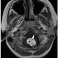
FIGURE 10.15 Pulmonary artery sling in a 3-day-old girl who died of complications of tracheal atresia (with complete distal rings) and pulmonary hypoplasia. The left pulmonary artery (arrow) branches off a dilated pulmonary trunk and courses posterior to the narrowed trachea (T). In this example, the right lung is attached to the left lower lobe (“horseshoe lung”) (asterisk).

PAS imaging findings mainly depend on the type of PAS and presence of coexisting anomalies. In type I PAS, substantial right-sided hyperinflation or atelectasis because of partial obstruction and right mainstem bronchomalacia may be appreciated on frontal chest radiograph. A right-sided tracheal bronchus may be observed in some instances. In type II PAS, bilateral hyperinflation may be present, particularly in cases associated with long-segment tracheal stenosis. In this situation, the trachea may appear narrow or difficult to resolve on a frontal chest radiograph, and the carina may appear low and horizontal in position. This constellation of radiographic findings should raise suspicion for underlying type II PAS.57,59 Occasionally, on lateral chest radiographs and on lateral esophagograms, a small, rounded, soft tissue density may be present between the midtrachea and the esophagus, consistent with the presence of an anomalous LPA coursing between these two structures. This may be seen in both types of PAS.50,57,59

Only gold members can continue reading. Log In or Register to continue

Stay updated, free articles. Join our Telegram channel

Oct 13, 2018 | Posted by in PEDIATRIC IMAGING | Comments Off on Great Vessels

Full access? Get Clinical Tree

Get Clinical Tree app for offline access