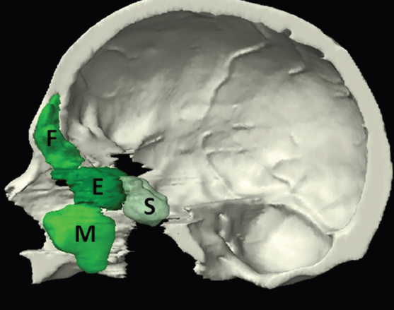
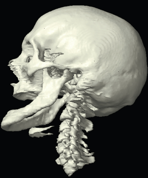
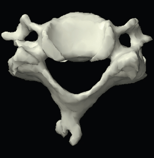
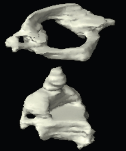
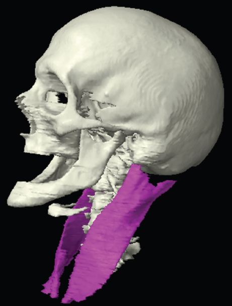
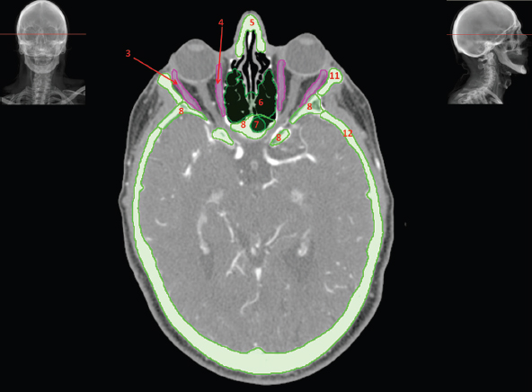
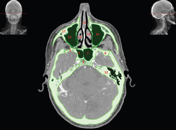
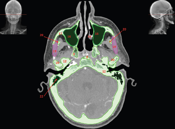
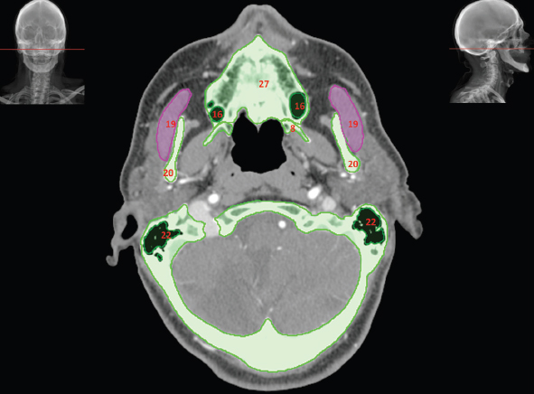
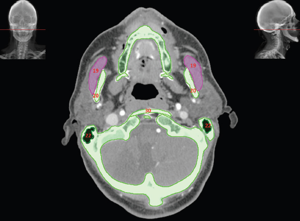
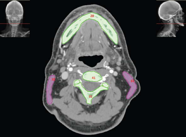
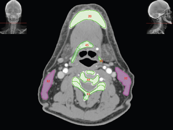
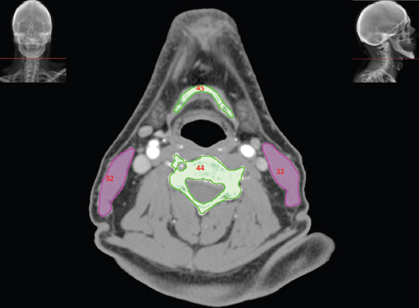
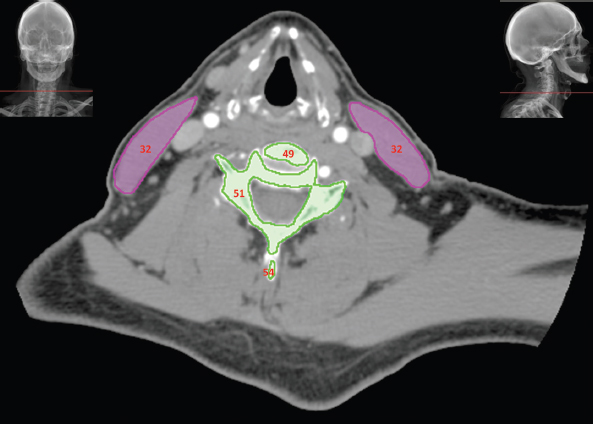
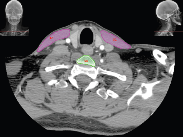
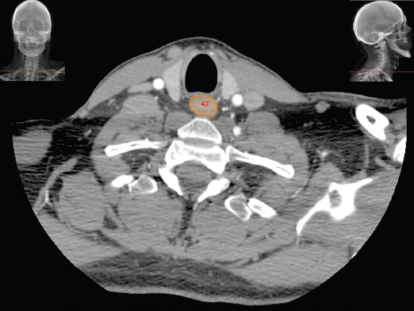
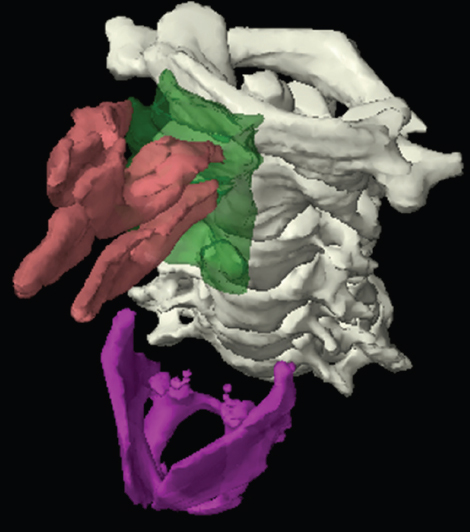
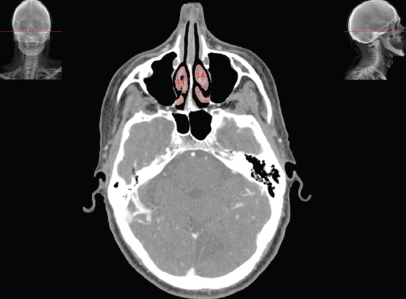
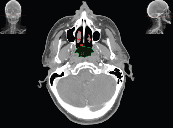
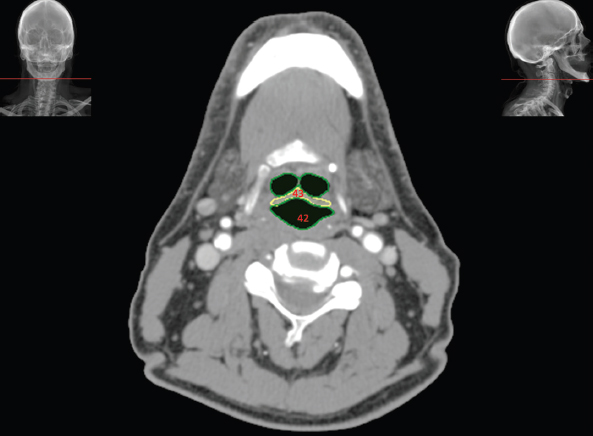
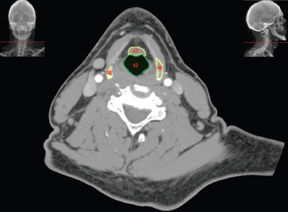
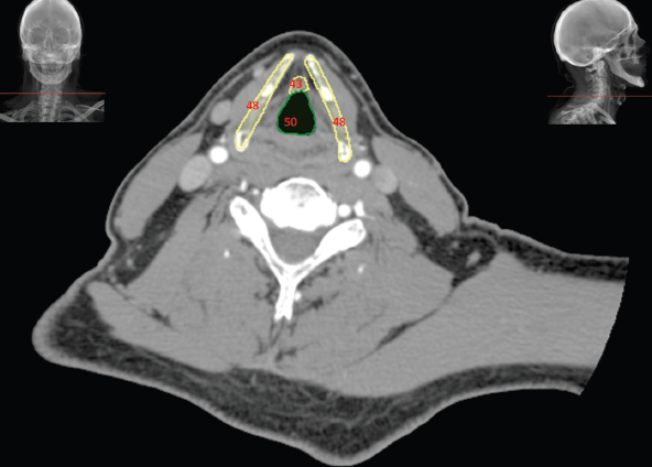
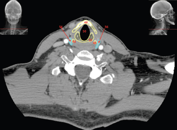
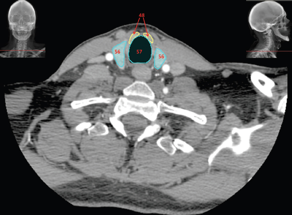
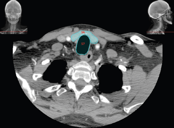
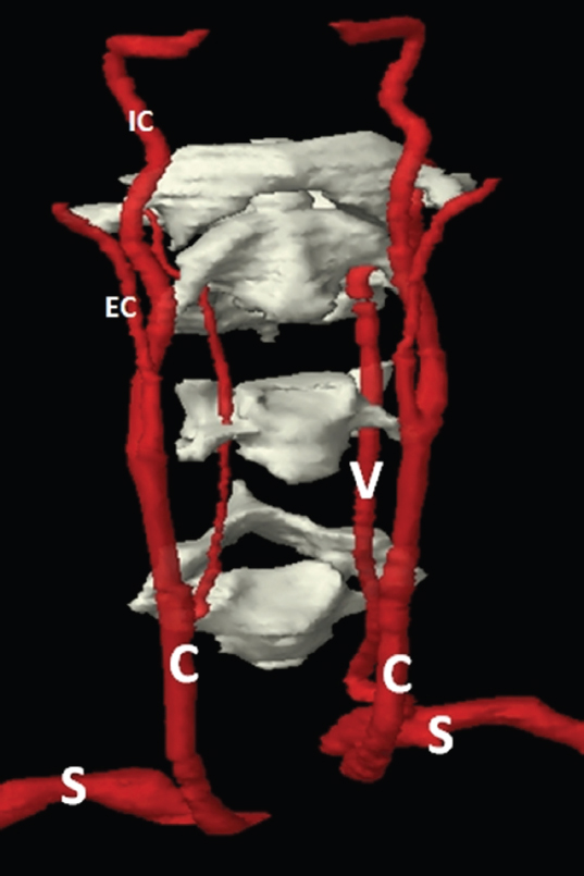
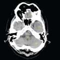
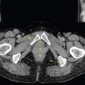
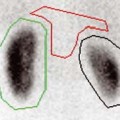
Although there are a large number of small bones in the head and neck region, it is not necessary for the therapy radiographer to be able to identify them all on CT. The bones can be considered as three main groups: the skull, hyoid bone and cervical vertebrae. The skull is made of 28 bones grouped as either cranial bones that form the chambers holding the brain or as facial bones. Although normal CT does not demarcate the individual bones well, an understanding of the general whereabouts and appearance of a few key bones is useful for radiotherapy practice. Figure 4.1.1 One of the most useful bones to identify is the keystone of the skull: the sphenoid bone, as shown in Figure 4.1.1. This sits in the middle of the skull, forming essential parts of the cranium and allowing for connection of key facial bones too. Amongst its many features are grooves for the carotid arteries and optic nerves, the pituitary fossa, roof of the nasopharynx, support for the brain stem and the large sphenoid sinus (S in Figure 4.1.2). The sphenoid sinus occupies the midline superior to the pharynx and curves up both anteriorly and posteriorly to the pituitary fossa. There are two superior projections of the sphenoid: the anterior and posterior clinoid processes and these form the anterior and posterior walls of the pituitary fossa. Figure 4.1.2 There are several other sinuses in the skull as shown in Figure 4.1.2 in green. The maxillary sinuses (M) on either side of the nasal cavity sit in the maxillae. The frontal sinus (F) is situated medially and superiorly to the orbits in the frontal bone. The ethmoid sinus (E) or ‘labyrinth’ runs between these three above the nasal cavity and between the orbits. These sinuses are important navigational landmarks in CT anatomy. There are other air-filled cavities in the skull. The main structures of the hearing apparatus are located in passageways in the petrous ridge of the temporal bone. At the inferior part of the skull, the mastoid processes are formed from the occipital bones and can be easily palpated posteriorly to the inferior of the pinna. These processes contain air cells to help lighten the skull and are easily identified by their bubbly appearance on CT. The mandible is a separate bone to the skull, featuring a vertical arm ‘ramus’ on each side and the curving ‘body’ forming the lower jaw. It connects to the skull via the temporomandibular joint between the posterior part of the superior ramus and the temporal bone. See Figure 4.1.3. This joint allows the mandible to pivot during mastication or speech. Anterior to the joint, the mandible ramus has a slight superior protrusion called the coronoid process that can be seen to disappear behind the zygomatic arch. This appears on CT as an island of bone surrounded by soft tissue and should be noted to avoid confusion. Figure 4.1.3 The other separate bone in the head and neck region is the hyoid bone, seen in Figure 4.1.3 between the mandible and the spinal column. This small horseshoe-shaped bone is found superiorly to the larynx and allows for attachment of both larynx cartilages and tongue muscles. It is unique in the body since it does not articulate with any other bones. There are seven cervical vertebrae, as seen curving under the skull in Figure 4.1.3. These are smaller than the other vertebrae in the body since they bear less weight. They are also characterised by the presence of ‘transverse foraminae’, which are small holes lateral and slightly anterior to the vertebral bodies. The foraminae can be seen in Figure 4.1.4 and form a passageway for the vertebral arteries that help supply the brain with blood. The first and second cervical vertebrae (Figure 4.1.5) are atypical in appearance, to allow rotation of the head. The first cervical vertebra is named ‘the atlas’ after the Greek Titan Atlas who bore the world on his shoulders. It has a small body and mainly comprises an anterior and posterior arch, making it resemble a ring. Figure 4.1.4 Figure 4.1.5 The second cervical vertebra is known as ‘the axis’ and it features a long ‘odontoid process’ or ‘dens’ that penetrates superiorly through the atlas, enabling rotation. For radiotherapy purposes, the muscles of the head and neck mainly have value in terms of locating other more relevant structures. The long twisted journey of the sternocleidomastoid muscle is a prime example, as shown in Figure 4.1.6. Each one starts at the sternum and the clavicle at the anterior of the body and travels superiorly, laterally and posteriorly to meet the ipsilateral mastoid process. It is of value since, for much of its length it overlies the carotid sheath containing the carotid artery, jugular vein and jugular lymph node chain. Figure 4.1.6 Figure 4.1.7 The other important muscle to be aware of is the masseter muscle, as seen in Figure 4.1.7. This lies along the lateral side of the mandibular ramus and, along with the pterygoid muscle medially to the ramus, helps with mastication. It is important to identify this muscle since the parotid gland overlies it and distinguishing between the two structures is vital. Figure 4.1.8 When viewing CT images within the head and neck, it should be noted that the region includes a wide range of CT tissue densities, from air passages to bony structures. This can make it difficult to select windows to view all tissue densities. Soft tissue window settings are probably the best, although bone or even ‘neuro’ windows may be useful. It should also be noted that above the hyoid most structures are symmetrical (assuming positioning is accurate); asymmetry is usually a sign of pathological process or disease. In Figure 4.1.8 the nasal bones (5) can be seen immediately anterior to the nasal cavity. Lateral to the nasal cavity are the cells of the air-containing ethmoid labyrinth (6). The ethmoid air cells form a honeycomb labyrinth of 3-18 air pockets per side, each separated by a thin layer of bone covered with a very thin layer of soft tissue mucosal lining. Separating the orbital cavities from the ethmoid labyrinth are thin bony walls called the lamina papyracea which form the medial orbital walls along with the lacrimal bones. The lateral orbital walls are formed by the sphenoid (8) and the zygoma (11). The orbital globes are clearly seen at the base of each orbital cavity. The densities of sclera, vitreous fluid and lens are clearly visualised. Figure 4.1.9 Figure 4.1.10 Either side of the orbital globes, two of the four main rectus muscles are seen. The medial (4) and lateral rectus (3) along with the superior, inferior (13 in Figure 4.1.9), and oblique muscles are responsible for eye movements. The four larger rectus muscles enlarge with thyroid orbitopathy resulting in the characteristic staring of the eyes (Thyroid eye disease). The optic nerve extends centrally from the posterior aspect of the globe towards the apex of the cavity by the posterior wall of the sphenoid sinus (8). In Figures 4.1.9 and 4.1.10 the nasal cavity is clearly divided by the central nasal septum (15) and more lateral conchae (14). Figure 4.1.11 The masseter (19) in Figures 4.1.11 to 4.1.17 originates from the zygomatic arch and extends superficially over the ramus of the mandible (20). The muscle is commonly ovoid in cross-section, but can be rounder and enlarged, associated with benign muscle hypertrophy linked with excessive chewing and teeth grinding. Relevant neighbouring structures, posterior and lateral to the masseter muscles, are the parotid glands, discussed below. The hinged temporomandibular joint is seen in Figure 4.1.11 where the head of the mandible (20) can be seen articulating with the temporal bone (12). The air-containing cavities within the head and neck may appear quite similar since many are surrounded by high density bone and filled with low density air. Although similar in appearance, some are part of the paranasal sinuses, some are cavities linked to external orifices (ears, nose and mouth) and some are seemingly closed cavities within bony structures. Figure 4.1.12 Figure 4.1.13 These cavities normally contain air and have a high inherent contrast to the surrounding bone, making them relatively easy to locate on CT However, these cavities may contain fluid or soft tissues associated with sinus disease, infective or infiltrative processes. The paranasal sinuses (16) are visualised in Figures 4.1.8 to 4.1.13, and are all actually extensions of the respiratory part of the nasal cavity. The development of infection or tumour within the sinus cavities can spread relatively easily through the air filled spaces and along their adjoining openings, occasionally into neighbouring sinus cavities. All the paranasal sinuses are normally well aerated with relatively smooth wall contours and are all linked via various openings. Some of these are poorly located, such as the hiatus semilunaris. High up in the maxillary sinuses (16) on their medial wall, these allow drainage into the nasal cavity only when the sinus is nearly full with the head erect. Figure 4.1.14 There are corresponding named sinus cavities within the frontal, ethmoid (6), sphenoid (7) and maxillary (16) bones as seen in Figures 4.1.8 to 4.1.13. Directly posterior to the ethmoid labyrinth, the paired sphenoid sinuses (7) are seen within the body of the sphenoid bone (8). Each sinus is likely to show asymmetry as seen in Figure 4.1.10, where the left sphenoid sinus is considerably larger than the right. The thin bony midline septum may also be deviated left or right. The sphenoid sinuses and bone are located centrally within the skull base, and are adjacent to several important structures. The pituitary gland, carotid canal and foramen lacerum (carrying the internal carotid arteries) are all located very close to the sphenoid sinus. Tumours infiltrating the sphenoid bone will have obvious complications during treatment. The maxillary sinuses or ‘antra’ (16) are two relatively symmetrical and large pyramidal shaped cavities within the maxillary bones (17 in Figures 4.1.10 to 4.1.13). The floor of each maxillary sinus is formed by the alveolar recesses in the hard palate (27) and it is not uncommon to see roots of molar teeth extending into the sinuses, covered only by a thin layer of bone and mucosal lining. Figure 4.1.15 Figure 4.1.16 The nasal cavity (18) links the external nares to the roof of the mouth. It is divided into two by the nasal septum (15) as seen in Figures 4.1.8 to 4.1.12. The septum has thin cartilaginous and bony sections formed by the perpendicular ethmoid plate, vomer and septal cartilage. Either side of the nasal septum in Figures 4.1.9 to 4.1.13 can be seen the nasal conchae (14). The thick lining of the nasal conchae causes them to enhance vividly following the injection of IV contrast agents. Figures 4.1.10 to 4.1.14 show the mastoid air cells (22) within the otherwise very dense petrous temporal bones (12). The sternocleidomastoid muscle (32 in Figures 4.1.15 and 4.1.16) attaches to the lateral surface of the mastoid process and adjacent occipital bone. Figure 4.1.17 The masseter muscle (19) is relatively small in cross-section in Figure 4.1.17, as many of its fibres have inserted slightly superiorly on the ramus of the mandible (20). The mandible (20) is seen in Figures 4.1.11 to 4.1.19. In many patients there are teeth sited in the alveolar sockets; however the frequent presence of very dense amalgam dental fillings causes considerable streak artefacts across the adjacent soft tissues. These artefacts are described in more detail in the introduction (pages 14-16). The edentulous (toothless) patient selected to illustrate this text was specifically selected, as once their false teeth had been removed prior to imaging, there would be little or no imaging artefacts present in the oral cavity. This does make illustration of normal teeth slightly difficult, but does illustrate normal soft tissue CT anatomy which can be applied in clinical practice. It should be noted, however, that in the edentulous mandible the alveolar sockets will become absorbed over time, and several years after the teeth have been removed most of the alveolar bone and processes will be entirely reabsorbed. This will give the body of the mandible a narrower profile. Figure 4.1.18 Figure 4.1.19 In Figure 4.1.11, medial to the masseter muscle (19), can be seen the mandibular coronoid processes, separated from the temporomandibular joint by a gap called the mandibular notch. Below the notch, in Figure 4.1.12, the superior aspect of each ramus can be seen in cross-section tapering from the neck of the mandible. At the angle of the mandible in Figure 4.1.17, the mandible curves anteriorly to form the body and recognisable horseshoe shape as seen in Figure 4.1.18. The hyoid bone (45) is seen in Figures 4.1.19 and 4.1.20. The hyoid, along with the mandible and styloid processes attaches to muscles from the floor of the mouth, tongue and larynx interiorly. The hyoid has a body anteriorly and both lesser and greater horns or cornu projecting posteriorly. Figure 4.1.20 The bony structure of the cervical spine can be seen in Figures 4.1.14 to 4.1.22. Depending upon the degree of cervical flexion and gantry angulation, there may well be sections of multiple cervical vertebrae included in the scan plane and it may be difficult to recognise specific vertebral levels. The viewer should scroll through contiguous images following the path of the cervical spine, perform sagittal reformats or use planning software to plot reference lines on the scout view. Elements of C1 and C2 are quite recognisable, as seen in Figure 4.1.15. The lateral masses of C1 (30) can be seen either side of the odontoid process of C2 (31). The left vertebral artery is clearly seen within the transverse process of C1 (30). This is not clearly demonstrated on the right, and there is also partial voluming of the occipital bone on the left. Slightly interiorly in Figure 4.1.16, the posterior arch of C1 can be seen (30) posterior to the larger body of C2 (31). Figure 4.1.21 Figure 4.1.22 The sternocleidomastoid muscle (32) is a key landmark in the neck. It divides the neck diagonally into the anterior and posterior cervical triangles. These regions are used for descriptive purposes when indicating clinical anatomy and disease spread. The sternocleidomastoid muscle is a broad strap muscle and attaches interiorly to the anterior surface of the manubrium of the sternum and superior surface of the medial third of the clavicle. From here, the muscle flattens and ascends slightly obliquely, as can be seen in Figures 4.1.20 to 4.1.22. Deep to the muscle is the carotid sheath anteriorly. As the muscle ascends further in Figures 4.1.17 to 4.1.19, it flattens and twists its axis, and ascends parallel to the lateral aspect of the neck at approximately C4/5. The digestive system starts with the oral cavity and for much of radiotherapy practice this will either be of little relevance or will be filled with a mouth bite. The large genioglossus muscle (tongue) fills most of the cavity normally. It is bounded superiorly by the hard palate anteriorly and then the sloping roof of the soft palate posteriorly. It is in this region that food receives secretions of saliva from three paired glands as seen in Figure 4.2.1. Figure 4.2.1 The parotid glands (P) are the largest and are located laterally to the masseter muscle and anterior to the pinna. They curve round to penetrate surprisingly deep behind the posterior of the mandibular rami. The parotid (‘Stenson’s’) duct can just be seen extending anteriorly along the masseter muscle. The salivary glands are lobulated and contain fluid; thus on CT they have a reduced density and characteristic ‘bubbly’ appearance. The submandibular glands (Sm) are the next largest glands and are located behind and under the angle of mandible. Although the parotid gland is the largest, it only accounts for approximately 25% of total salivary volume and the submandibular glands account for 60% to 65%. The final salivary glands are the small sublingual glands (SI) found just behind the mandible in the anterior floor of mouth. They lack the obvious shapes of the other salivary glands, forming a small horseshoe shape at the anterior of the floor of mouth. Localisation of the salivary glands on CT may be quite difficult for the relatively inexperienced viewer, yet is of great clinical importance when considering treatment fields for some head and neck cancers. It is well documented that irradiating the salivary glands produces a range of acute and chronic complications, such as xerostomia where salivary flow can be compromised following radiotherapy. Here are several hints to help localise the salivary glands on CT: • CT density Typically, the parotid glands are composed of fatty glandular tissue and demonstrate an intermediate CT density between that of fat and muscle, approximately -5HU. The submandibular glands have a slightly higher density than the parotid glands. The parotid gland has a slightly inhomogeneous appearance. Gland density is age dependent; the parotid gland may be isodense with adjacent muscle tissues in children and young adults. Age-related changes bring about a significant fall in gland density due to an increase in fibro-fatty glandular and adipose tissue. The reduced density does have the advantage of improving border demarcation. • Position The salivary glands, although capsulated, are relatively pliable and are easily displaced by adjacent abnormalities or more rigid structures. Each of the three glands is usually paired, and displays symmetry, although the parotid gland may be more irregular, with accessory glands along the parotid duct. • Appearance It is not uncommon to see calcified deposits (‘calculi’) in the parotid and submandibular glands. Multiple dilated ducts may be seen in the presence of glandular abnormalities. Radiation can induce a range of changes within the parotid glands. These may be transient or chronic, and most patients will have chronic changes above 30-40Gy. Glandular swelling will be evident in the acute phase due to leakage from damaged endothelial linings. There will be diffuse heterogeneous enhancement following IV contrast. Fibrosis and atrophy occur in the chronic stage, and the gland will demonstrate higher CT density and reduced volume. Figure 4.2.2 Figure 4.2.2 shows the next stage of the digestive system. After the oral cavity, the digestive tract passes the pointed tip of the soft palate, known as the uvula and continues into the oropharynx (0). The oropharynx is the shortest part of the pharynx and leads interiorly to the hypopharynx (H) at the level of the epiglottis. The epiglottis is part of the larynx and serves to direct air and food into the larynx and oesophagus respectively. It can be seen that the oropharynx is located behind the mandible body and the hypopharynx behind the hyoid bone. From the posterior part of the hypopharynx, the digestive system continues into the oesophagus (Oe) which runs behind the larynx (L) and then behind the trachea (T) in the thorax. Figure 4.2.3 Figure 4.2.3 is a CT section just inferior to the temporomandibular joints. The parotid gland (21) is seen wedged between the ramus of the mandible, masseter muscle and ear. As with many structures within the body, its name describes its location (para – near or around and otis – ear). The parotid gland is visible in Figures 4.2.3 to 4.2.6. The parotid has two lobes: superficial and deep. The larger superficial lobe extends irregularly and overlaps the posterior part of the masseter muscle and the majority of the mandibular ramus. The deep lobe extends behind the ramus of the mandible, enclosing the retromandibular vein and branches of the external carotid artery. The tip of the deep lobe extends medially to the fatty parapharyngeal space seen in Figure 4.2.5. Of clinical interest, it should be noted that there are approximately 20 intraparotid lymph nodes that are first order drainage for the external auditory canal, pinna and surrounding adjacent scalp. Figure 4.2.4 The left parotid duct can be seen crossing the superficial aspect of the masseter muscle in Figure 4.2.4. The duct tapers off and narrows as it leaves the anterior edge of the gland. The duct is not as well demarcated on the right, as accessory portions of the parotid gland are seen to extend across the right masseter muscle. This is a common finding, and these accessory parotid glands may well appear to be completely separate to the gland itself, but will still be associated with the duct. Figure 4.2.5 Figure 4.2.5 demonstrates how the deep lobe extends posterior and medial to the mandibular ramus. A finger-like projection of the gland extends posterior to the ramus of the mandible. The tongue (28) can be seen occupying the oral cavity surrounded by the horseshoe shaped gums. The soft palate (29) is seen draping over the posterior dorsal aspect of the tongue. Figure 4.2.6 Figure 4.2.6 shows the small grape-like appearance of the uvula (37), which hangs off the inferior aspect of the soft palate into the oropharynx. Figure 4.2.7 demonstrates the base of the tongue (28) in the floor of the mouth. The tongue is divided by the median septum, separating symmetrical halves, and also has a base, body and apex. The median septum can be seen in Figure 4.2.6 as a faint soft tissue line running centrally along the tongue. This division is also seen in Figure 4.2.7, where each side of the genioglossus muscle is separated by the lingual septum. Figure 4.2.7 Both sublingual glands (40) can be seen in Figure 4.2.7 These paired salivary glands can be relatively difficult to demarcate on CT since they are not capsulated. The submandibular glands (39) however are much larger and can be seen in Figures 4.2.6 to 4.2.9. The corresponding greater horn of the hyoid bone is medial to each gland, separated by a thin fat plane. Figure 4.2.8 Demarcation of the submandibular (Wharton’s) duct is difficult on CT as it has a relatively tortuous route from its anterior aspect to either side of the lingual frenulum. The duct is approximately 50mm long, similar to the parotid duct, but is much smaller in calibre. Due to the lengthy and tortuous nature of the duct, the submandibular gland commonly displays salivary calculi. This is of clinical relevance, as an obstructed and enlarged submandibular gland may also mimic the appearance of a large malignant lymph node or primary carcinoma. Associated lymph nodes may be partially embedded within the gland laterally, or lie lateral to the gland. Figure 4.2.9 Below the oropharynx (38) can be seen the hypopharynx (42) in Figures 4.2.8 and 4.2.9. Air within the lumen enables the epiglottis (43) to be clearly visualised. The leaf-shaped epiglottic cartilage (43) projects from the posterior surface of the thyroid cartilage superiorly into the oropharynx. The epiglottis is suspended from the body of the hyoid bone by the hyoepiglottic ligament in the midline. This ligament is covered by a thin mucous membrane called the glossoepiglottic fold and together they can be seen in Figure 4.2.8. The two smaller air-filled spaces anterior to the epiglottis are the valleculae, which are essentially two small depressions either side of the glossoepiglottic fold. Figure 4.2.10 The inferior stalk of the epiglottis (43) is seen just anterior to the larynx (50) in Figure 4.2.10. At this level (about C6) it is difficult to fully demarcate the boundaries of the origin of the cervical oesophagus (47). The oesophagus sits between the posterior of the larynx (50) and the inferior constrictor muscle of the pharynx. Figure 4.2.11 More interiorly, in Figure 4.2.11, the oesophagus is more clearly defined. It is larger in cross-section and the muscular external borders are well demarcated against the lower density surrounding fatty tissues. From this level, the oesophagus occupies its well recognised course slightly to the left of midline, anterior to the vertebral bodies, and behind the trachea. There is normally a thin fat plane separating the flattened posterior border of the trachea and the anterior of the oesophagus, called the tracheoesophageal groove. This contains loose adipose connective tissues, the recurrent laryngeal nerve and some paratracheal lymph nodes. The parathyroid glands are also situated laterally within the tracheoesophageal groove. In terms of anatomical description of the upper respiratory tract, the anatomy is subdivided into nasal cavity nasopharynx, oral cavity, oropharynx and hypopharynx. Anatomy and pathology is also described as being either supra or infra hyoid. Some texts refer to the anatomy as the aerodigestive tract. Air enters the respiratory system via the nostrils (the external nares) and passes to the nasal cavity. This is bisected by the nasal septum and further subdivided by the curtain-like nasal conchae (or turbinate bones). These have a rich blood supply and are hairy so act as both radiators to warm the air and filters to extract particles. At the posterior of the nasal cavity through the internal nares lies the nasopharynx. The long tube of the nasopharynx extends from the inferior of the sphenoid bone down to the oropharynx at the level of the soft palate. The nasopharynx can be seen in green in Figure 4.3.1 behind the pink nasal conchae leading down to the larynx. Figure 4.3.1 Figure 4.3.2 From this point, the respiratory passage is shared with the digestive tract through the oropharynx and hypopharynx until the epiglottis is reached, as seen in Figure 4.3.2. The epiglottis (E) is a leaf-shaped piece of cartilage that is technically part of the larynx. It serves to direct air into the larynx most of the time but during the swallowing reflex it directs food and drink into the oesophagus. The larynx is a cartilaginous structure formed from three large pieces of cartilage and three small paired cartilages. The largest part of the larynx is formed by the thyroid cartilages (Th). These form the side walls and anterior of the larynx and form an inverted V-shape in cross-section. The superior anterior region of the thyroid cartilage is notched and the prominence of this structure is commonly known as the Adam’s Apple. For clinical descriptive purposes, the larynx is divided into three distinct areas: the supraglottis, glottis and subglottis. The supraglottis extends from the tip of the epiglottis to the laryngeal ventricles. It is a relatively large area of the larynx and contains the epiglottis, pre-epiglottic fat, false vocal cords and arytenoid cartilages. The glottis is the central section of the larynx, containing only the true vocal cords, responsible for the origins of voice production. The subglottis extends from the inferior surface of the true vocal cords to the inferior edge of the ring-shaped cricoid cartilage (C). Extending interiorly from this is the trachea (Tr). Other smaller paired cartilages can be found at the posterior of the larynx. These are the arytenoids, the horn-shaped cuneiform and tiny corniculate cartilages. Figure 4.3.3 Although not part of the respiratory system, the thyroid gland is physically close to the larynx so will be mentioned briefly at this point. Responsible for regulation of metabolism, it lies inferior and anterior to the thyroid cartilage. It consists of two lobes connected by an ‘isthmus’. The upper lobe on each side is considerably longer than the lower lobe, giving the thyroid gland a shape like an inflated rugby post as seen in Figure 4.3.3. The thyroid gland enhances strongly with iodine-based contrast on CT due to its natural absorption of iodine. When viewing the respiratory system within the head and neck, it is important to remember the wide range of tissue densities within the whole series of images. By its very nature, the respiratory tract should be well aerated, allowing the passage of air in and out of the lungs, and therefore full of air. Air will always appear black, irrespective of window settings. In many instances in the presence of tumour pathology, the aerated spaces may be either compressed or infiltrated by soft tissue masses. There may be relatively unchecked spread of disease within and along the linings of aerated cavities, as there are few boundaries to impede disease progression. Within the head and neck region there are other air-containing cavities adjacent to and linked via various openings. The paranasal sinuses, described in section 4.1, are extensions of the respiratory part of the nasal cavity, and are adjacent to both the nasal cavity and nasopharynx. Although linked, it is important to be able to distinguish between the adjacent aerated cavities. Poor image resolution and perception, predominantly affected by reconstruction algorithm, slice thickness and window settings, can make some of the bony boundaries very difficult to appreciate. This is demonstrated in Figure 4.3.4 where it is difficult to demarcate the lateral wall of the left nasal cavity. The thin bony walls separating the sinus and nasal cavity appear to be missing. When trying to demarcate such fine structures in the head and neck, it is vitally important to view the images using bone and lung windows as well as soft tissue window settings, using the thinnest slices possible. The soft tissue windows used in Figures 4.3.4 to 4.3.12 enable high image contrast and most of the structures within the upper respiratory tract are well demarcated. Figure 4.3.4 The nasal septum bisects the nasal cavity in the midline, as seen in Figure 4.3.4. The septal cartilage and perpendicular bony plate of the ethmoid are clearly visible. As mentioned in previous chapters, anatomy within the suprahyoid region tends to be symmetrical, left and right, simplifying recognition of abnormalities. However, it is certainly not unusual to see a deviated nasal septum, occasionally congenital or commonly attributed to previous nasal trauma. The nasal conchae (14) are seen either side of the septum. These hang down from the lateral nasal walls forming scrolllike shapes, and project medially and interiorly. The paired superior, middle and inferior nasal conchae have a rich arterial supply and plentiful venous drainage. As a consequence, nasally inhaled air passing over them is warmed. Radiologically, this is noticeable after administration of IV contrast agent when the nasal mucosa surrounding the conchae enhance vividly. Figure 4.3.5 Posterior to the nasal cavity (18) the nasopharynx (24) is seen in Figure 4.3.5. There are no physical boundaries between the nasal cavity and nasopharynx. Within the lateral walls of the nasopharynx in Figure 4.3.5can be seen the torus tubularis. They are small, rounded soft tissue structures, just posterior to a V-shaped indentation on the lateral nasopharyngeal wall. The indentations are the pharyngeal openings to the pharyngotympanic (auditory or Eustachian) tube. The torus tubularis is the cartilaginous hood that projects over the opening to the pharyngotympanic duct. Figure 4.3.6 Figure 4.3.6 demonstrates the hypopharynx (42) level with the body of the hyoid bone. The inferior aspects of the hyoid bone suspend the larynx by the thyrohyoid membrane. Figure 4.3.7 Figure 4.3.7 shows the air-filled hypopharynx (42) posteriorly to the stalk of the epiglottis (43). The laminae of the thyroid cartilages (48) are well demonstrated in Figure 4.3.8. The laminae are essentially two quadrilateral cartilaginous plates, with projections extending from the posterior corners. These are the superior and inferior thyroid cornuae or horns. The laminae (Latin – thin plates) converge and are fused anteriorly at the laryngeal prominence in the midline. They are not totally fused anteriorly and in Figures 4.3.8 and 4.3.9 there is a gap or notch. This is called the thyroid notch, and when viewed anteriorly it forms a V-shaped groove. Figure 4.3.8 Figure 4.3.9 There are flecks of calcification within the thyroid cartilages (48) in Figures 4.3.7 to 4.3.10. All the cartilages within the larynx are composed of hyaline cartilage and normally undergo some sort of calcification or endochondral ossification. Not all of the cartilages calcify simultaneously, and this process can vary with age and gender. Calcification is usually evident in the paired arytenoid cartilages (52) by the third decade, and the whole of the thyroid cartilage usually demonstrates some level of calcification by the seventh decade. However, this is less extensive in females where calcification is minimal in the anterior aspects of the thyroid gland. This is radiologically significant as many aspects of the laryngeal cartilages are evident on CT without IV contrast, and can also be well demarcated even on plain film imaging. Whilst the thyroid cartilage covers the anterolateral aspects of the glottis, the cricoid (55) cartilage (from the Greek for ring) encircles the subglottic area. The ‘band’ of the ring faces anteriorly, as seen in Figures 4.3.10 and 4.3.11. It is much broader posteriorly. The vocal cords are level with the superior aspect of the cricoid cartilage. Figure 4.3.10 In Figure 4.3.11 the trachea (57) is suspended from the inferior aspect of the cricoid cartilage by the cricotracheal ligament, which is difficult to appreciate in cross-section. Although not part of the respiratory system, the thyroid gland (56) can be seen in Figures 4.3.10 to 4.3.11, adjacent to the trachea. The thyroid is of clinical significance due to its location within the visceral space and likely subsequent mass affect on the trachea and airways following any degree of enlargement. The thyroid gland is surrounded by a thin fibrous capsule, which is in turn covered by a superficial layer of the deep cervical fascia, which adheres to the trachea. The gland is also normally quite mobile, and moves superiorly with the larynx during swallowing. Figure 4.3.11 Figure 4.3.12 The gland is located inferior to the larynx, and has two relatively large lobes, left and right. The pear shaped lobes extend either side of the trachea (57) as seen in Figure 4.3.11. The lobes and thin ‘isthmus’ of glandular tissue crossing anterior to the trachea can be seen in Figure 4.3.12. The thyroid gland itself normally appears as a smooth soft tissue structure, appearing slightly hyperdense to the surrounding soft tissues because of the relatively high iodine content (approximately 65HU). The thyroid gland is also highly vascularised, receiving almost 80 to 120ml of blood per minute from the superior and inferior thyroid arteries, and as such, following IV contrast agent, the gland will enhance vividly. The gland should normally be heterogeneous, but may display a cystic, solid, haemorrhagic or calcified appearance, particularly if the gland is enlarged due to goitre. In Chapter 3, it was explained how the first main arteries originating from the aorta are the brachiocephalic (which bifurcates into the right subclavian and right common carotid) and the left common carotid and left subclavian arteries. The main vascular supply to the head and neck arises from the common carotid (C) and vertebral (V) arteries. Both vertebral arteries are the first main vessel branching off each subclavian (S) vessel. The vertebral artery makes its way to the cervical vertebrae and ascends through the transverse foraminae, as seen in Figure 4.4.1. It then bends over the atlas and enters the skull through the foramen magnum. The common carotid artery winds its way towards the central base of skull, bifurcating at approximately C3/C4 into the internal (IC) and external (EC) carotid arteries. Of the two, the internal carotid is larger in lumen. The internal carotid artery is destined for the brain and penetrates the skull through the sphenoid bone. The external carotid supplies the extracranial tissues and splits into smaller branches to supply the facial structures. Deoxygenated blood from intracranial structures exits the skull via the internal jugular vein. This accompanies the internal carotid artery inside the carotid sheath. Extracranial drainage passes into a number of veins including the external, posterior and anterior jugulars which ultimately drain into the subclavian veins. Figure 4.4.1
4.1Musculoskeletal System


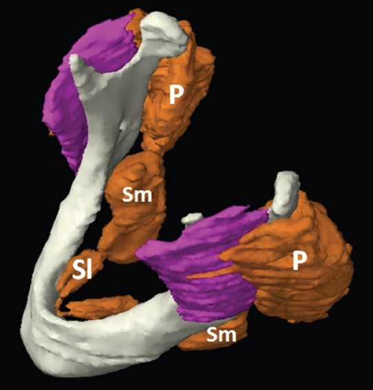
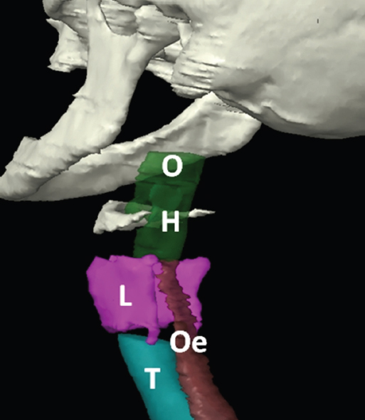
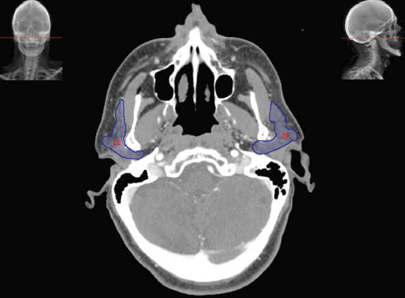
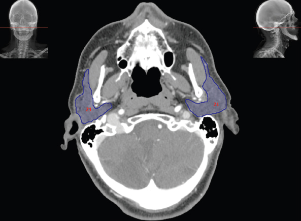
4.2Digestive System


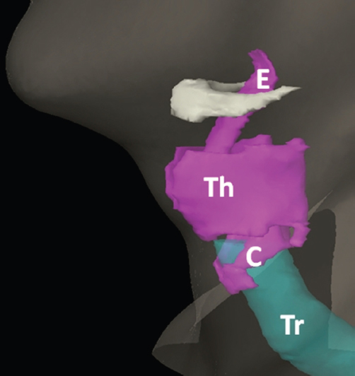
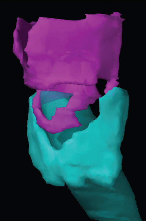
4.3Respiratory System

4.4Circulatory System
Related posts:
Stay updated, free articles. Join our Telegram channel

Full access? Get Clinical Tree


