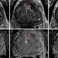
Fig. 3.1
(a) T2-weighted imaging, (b) ADC map from diffusion-weighted imaging, (c) dynamic contrast enhancement MRI demonstrating early and avid gadolinium enhancement, and (d) spectroscopic imaging depicting a right mid-base peripheral zone lesion (arrow) (Adapted from George et al. [13] with permission)
Basics
Visualization and Application
Ultrasound (US) relies on the emission, reflection, and detection of high-frequency sound waves from organ boundaries and interface contingent on the change in density of the tissues contacted. This imaging technique is widely used in clinical practice, as a result of its many advantages including lack of patient exposure to toxic effects of radiation, real-time imaging capability, relatively low-cost, portability, and abbreviated learning curve for clinical use. Limitations of ultrasound imaging include its reliance on operator training and experience, reduced ability to access information about more distal structures or those hidden by variations of body habitus or those beyond low-density structures (lung, air-filled bowel loops, pneumoperitoneum), as resolution is distance and transmission dependent.
Developed in the 1970s, computerized tomography (CT) or X-ray computed tomography is a widely used imaging modality. It allows rapid high-resolution tissue imaging providing excellent delineation of anatomy. CT is a mainstay in the diagnosis and follow-up of clinical conditions in almost every medical and surgical specialty. CT has the capacity to guide the performance of percutaneous procedures, providing accurate location of instruments within three-dimensional regions of the body [16]. The main advantage of CT is its fast image acquisition and high resolution; significant disadvantages include exposure of the patient to ionizing radiation (especially cumulative exposure secondary to serial imaging) [17]. Ionizing radiation may expose patients to long-term cancer risk, particularly when exposed at early ages [18].
Positron emission tomography (PET) is a nuclear medicine technique which requires the administration of a radioisotope, a radioactively tagged chemical compound (radionuclide or tracer) to the patient. The subsequent gamma rays emitted from the patient as the radioisotope decays are captured, analyzed by computer, and portrayed as three-dimensional images locating the involvement of the functional processes of the administered chemical compound.
Fluoroscopy utilizes low-intensity X-rays to obtain “real-time” radiographic imaging. It is utilized as a diagnostic modality and during image-guided therapy [19]. The administration of intravascular contrast can allow for vessel mapping, facilitating therapeutic interventions such as drug delivery or angioembolization.
Magnetic resonance imaging (MRI) utilizes strong magnetic fields to polarize protons within the molecules of tissues via directed energy pulses. After magnetic alignment, protons move back to their aligned positions when the pulse is ended. The resulting waves are detected and captured so the computer may construct 3D images. By using both anatomical and functional MRI data, various tissue systems can be evaluated, based on the performance characteristics of each parameter, yielding high-quality diagnostic information.
Three-Dimensional Image Visualization
Typical radiographic imaging, X-ray, US, or fluoroscopy, is seen in the original plane as a two-dimensional (2D) image. More advanced imaging, CT, PET, and MRI, is computer processed allowing rendering in multiple planes. The multi-planar reconstruction (MPR) technique allows new images to be reformatted from their original plane (mostly axial) in coronal, sagittal, or oblique planes utilizing the pixel data acquired from the stack of planar images. MPR aids in visualization of anatomy by providing the perspective of structures within the entire volume that may not be readily apparent from base images. However, quality of MPR is dependent on base image acquisition and quality. The various approaches for 3D visualization and analysis of imaging datasets are subsequently described.
Surface rendering, or shaded surface display (SSD), operates on the assumption that a structure or organ can be displayed based on the surface estimated from an image (volume dataset) [20]. The surface is initially determined by segmentation which is accomplished by thresholding, or assigning each voxel intensity within the dataset to be within a predetermined attenuation range. Surface contours derived from the volume dataset are modeled as overlapping polygons, to represent the 3D object. SSD allows for swift image rendering; however, only a small portion of the dataset is employed, and it may be of limited utility where a discrete interface or boundary is not readily apparent [21].
Maximum intensity projection (MIP) rendering appraises each voxel along a continuous line throughout a dataset [22]. The maximum value voxel, or volumetric picture element, which essentially corresponds to a value on a grid in 3D space, is selected and used as the displayed value. Based on these displayed voxels, a 3D image is rendered. MIP is most commonly used in display and analysis of angiographic images and draws from only a small percentage of the entire volume dataset for rendering. Its shortcomings include lack of depth cues to assess spatial relationships and increased background “noise” due to display of only voxels with the highest intensity values.
Volume rendering is a technique that utilizes the entire volume dataset and assigns an opacity and color to each voxel which corresponds to tissue characteristics. It can display surfaces with shading and other parts of the volume simultaneously [23]. The highest image quality volume rendering method from 3D scalar data is by volume ray casting. In volume ray casting, a “ray” is projected through the volume, and the amount of intersection between the ray and a voxel determines the contribution to the voxel value. Weighted measures of the voxel values are calculated for each pixel and scales to a range of gray-scale values from which an image is constructed. As volume rendering incorporates the whole dataset, it requires complex algorithms and powerful computer processing equipment but has the capacity to display multiple tissues in addition to giving information on spatial relationship within the volume.
Registration
The goal of medical image registration is to find the ideal transformation that optimally aligns the anatomic structures of interest from the acquired image datasets. Correspondence is established between features in image datasets using a transformational model such that mapping of coordinates between these images corresponds to the same anatomical point. Registration allows clinicians to integrate information from different imaging modalities or time points. The term “fusion” refers to the step subsequent to registration that creates an integrated display of the data involved. However, it is often used to refer to the entire process of co-registration and co-display of the registered datasets. Applications of image registration are diverse and include surgical guidance, radiation planning, computer-aided diagnosis, and fusion of anatomic and functional imaging [24–27].
Image registration was first accomplished by physicians using “cognitive registration,” referring to the basic interpretations of imaging data and applying it to physical space based on cognitive estimations. Rapid technologic progress and research in the field has harnessed increased computational power to employ complex algorithms to deliver more accurate registration systems. Image registration is accomplished by incorporating information from one imaging modality and then applying it to a complementary modality and/or physical space to relate contrasting information from the different types of images. For example, when a suspicious lesion is only visualized on multiparametric MR imaging, MR/transrectal ultrasound fusion-guided biopsy can be performed whereby co-registration allows the real-time imaging advantage of US and resolution of MR to complement each other [13].
Current image registration techniques employ a combination of software-based algorithms and manual corrections to determine the spatial correspondence within 3D space. There are a number of algorithms that may be applied for registration, the common element being the ability to maximize a measure of similarity between a transformed “floating image” and a fixed “reference image” [28]. Intrinsic registration modalities rely solely on patient-derived imaging data and include intensity-based and geometric transformation-based models.
Geometric transformations require segmentation and include both landmark-based registration and surface-based registration techniques. Geometric transformation takes two forms, which are rigid and nonrigid or deformable algorithms. Rigid body registration is based on the notion that one image requires only translation and/or a rotation to achieve reasonable correspondence with a similar image, without change in the size or shape. Nonrigid or elastic registration is the more complex of the two types of transformations, where one image is elastically deformed to fit the second imaging and is used to describe changes in the shape, organ shift, or patient motion. Elastic registration employs a landmark-based approach in which corresponding landmarks (points, lines, surfaces, volumes) are forced (warped) to exactly match the other, potentially resulting in registration errors which may be compounded with each additional elastic transformation.
Landmark Based
Landmark-based registration identifies corresponding point landmarks as fiducial markers that appear in both images that are to be aligned [29]. These fiducial markers may be identifiable anatomical landmarks that remain unchanged such as bony points, cysts or calcifications, and the bifurcations of vessels. Alternatively, specific geometric features such as surface curvatures may be used. Point landmarks can be pins or markers attached to the patient’s skin or screwed into the bone where anatomy is not well defined. There are advantages and disadvantages of each using each type. In such cases, it is important to ensure that the coordinate of each fiducial marker is calculated accurately and that the coordinate computed in each modality corresponds to the same point in physical space so as to minimize fiducial registration error (FRE) [30].
At a minimum, three non-collinear points in the 3D space are required to determine a transformation between two sets of images though intuitively, additional fiducials minimize registration error [31]. The “centroid” point between each corresponding set of coordinates is determined, followed by rotation to diminish the sum of the square displacements between them. In order to objectively measure the validity and accuracy of registration, both FRE and target registration error (TRE) are reported. An FRE is the distance between selected markers in the 3D datasets being registered. FRE does not necessarily represent or guarantee accuracy of the registration or the fusion, but a low FRE is required for an accurate registration (Fig. 3.2). Accuracy reflects the degree of coincidence of a point of interest within the registered images. The difference between the point of interest within the image and its actual locations is described as the TRE [23]. The reported accuracy of 3D inter-modality registration (CT/MRI, PET/MRI) is between 1 and 3 mm [32–35]. Landmark-based registration does often require the user to select the points in each image for matching, which can be time-consuming and require clinical expertise. However, the landmarks represent a small proportion of the original data, and thus, optimization can be performed quickly with the need for limited computational power.
Fig. 3.2
Calculation of registration error. The fiducial registration error (FRE) is determined by the distance between corresponding fiducials in the reference dataset (shaded circles) and the floating dataset (unshaded circles) after registration is completed. The target registration error (TRE) is determined by the distance between the corresponding anatomical areas of interest in the two datasets (squares) after registration is completed (Adapted from Hutton and Braun [28] with permission)
Surface Based
Surface-based registration involves extraction of common features between sets of images, most often surfaces and curves. After surfaces are delineated, a transformation is computed that aims to minimize the distance between the two surfaces. The earliest algorithm, or “head and hat” algorithm, is a simplified manner in which performs the registration [36, 37]. The surfaces selected in the floating image set (“hat”) are registered to the corresponding nearest edges in the reference image set (“head”), so as the “hat” is moved/manipulated in a manner that best fits the “head.” Such methods are highly dependent on segmentation of surfaces that must correspond precisely and therefore necessitate high-resolution imaging to be most successful.
In an effort to overcome these limitations, the iterative closest point algorithm was proposed [38]. In the iterative closest point algorithm, the surface of one image is rendered using geometric primitives which may be facets or triangular sets, line segment sets, or parametric curves and surfaces. These primitives are then matched to the corresponding image, using a modeling equation by iteratively searching the closest points to minimize the disparity measure of this equation.
Voxel Intensity Based
Voxel intensity-based registration aligns images acquired from different imaging modalities based on imaging gray values, utilizing complementary information regarding similar structures without prior reduction as a result of segmentation [39]. As the full dataset is used, it requires high computational capacity. Paradigms for intensity-based registration include cross correlation (of extracted features), principal axes, and minimization of variance of intensity or histogram entropy. As intensity ratios between different modalities are often poorly correlated, increased interest has been given to the minimization of histogram entropy of different images. Entropy is essentially the probability of difference between the images being registered. The use of a 2D joint intensity histogram is correlated, point to point, between the images and their intensity. Each axis of the histogram represents possible gray-scale values in an imaging modality, and when images are perfectly aligned, the histogram is highly focused. The greater the error or difference in alignment, the greater the dispersion on the histogram is (Fig. 3.3) [40].
Fig. 3.3
Joint intensity histogram. Accuracy of voxel intensity-based registration can be visually represented by calculating joint entropy between the images being registered. When the modalities are similar and images are perfectly aligned, the histogram is highly focused. A greater degree of misregistration results in greater dispersion of “blur” within the histogram (Adapted from Hill et al. [29] with permission)
Tracking (Localizers)
Tracking refers to the transformation of image, patient, and instrument coordinates into a common reference system to identify its precise location within a 3D space. The clinical application of tracking or surgical navigation transcends medical specialties and has been exploited for percutaneous needle-based procedures (biopsy, catheter drainage, and ablation), endovascular interventions, minimally invasive surgical procedures, and even endoscopic procedures such as guidance for bronchoscopic biopsy of peripherally located lesions [41–43].
Optical tracking systems, the first to be widely adopted for clinical applications, operate via laser or infrared light emitting diodes and are tracked by reflection of light that is captured by an infrared camera. Alternatively, diodes placed on surgical instruments themselves may transmit signals back to a charge-coupled device camera. These systems represent the most accurate way of tracking instruments with spatial inaccuracy reported to be less than 1–3 mm [44, 45]. A major limiting factor in the use of optical tracking systems is the requirement of maintaining a “line of sight” (or unimpeded pathway) between the optical markers and the tracker camera [46]. As such, if an instrument tip is outside of the direct field, it is not visualized, but optically tracking the back of a rigid instrument allows for compensation by extrapolating the tips position. However, the line of sight requirement precludes the tracking of internal portions of an instrument, or if they are flexible or deformable [47].
Mechanical localizers are the earliest iterations that were employed for endonasal and neurosurgical therapies [48–51]. They consist of hardware with several degrees of freedom with encoders located at each joint, the entire device which is solely controlled by the operator. The exact location and orientation is calculated based on the feedback from geometric models derived from each encoder. These systems, though exhibiting a high degree of accuracy, can only track one object and may be large and cumbersome for use in a small operative field. A benefit of this system is that an instrument can be guided by the operator to a desired location within a physical space, fixed in a definite position and its location recorded [52].
The introduction of electromagnetic (EM) tracking systems was a proposed answer to the limitations of prior methods [53]. Electromagnetic tracking systems are based on the ability to localize a sensor which emits a weak electrical current in a weak pulsed electromagnetic field. An EM field generator is placed over the area of interest, creating a weak and differential electromagnetic field with a defined volume. The electric current emitted by sensor coils from skin fiducials, attached to or inside of instruments, is detected; and the strength of the signal based on its location within the EM field is triangulated to define its point in space [54]. Coils may be either 5 or 6 DOF (degrees of freedom). A single 5 DOF coil, though smaller, cannot determine the rotation component, which can be overcome by adding two or more 5 DOF coils, and most systems can track multiple coils within the geometry of the EM field. The reported accuracy is less than that of optical tracking systems (typically ~ 3 mm); however, “line of sight” tracking is not required allowing for tracking objects within the body within the EM field. Additionally, rapid technologic improvements now reportedly provide submillimeter tracking. A number of factors contribute to the utility of an individual EM tracking system. The refresh rate, working volume created by the field generator, and resilience must be considered [55]. A rapid refresh rate is needed when quantitative feedback is need such as during needle tracking, and images should be updated so as to not impede the physician performing the procedure. The size of the EM field created by the generator results in a fixed, arbitrary working volume in which the sensors must operate. As a result, it is imperative that the anatomy of interest and working area of a procedure be within the field. Signal intensity is dependent on proximity from the EM field generator; hence, the closer the coil is, the stronger the signal that is detected. Ferromagnetic materials from instruments and imaging equipment can cause interference resulting in distortions that may influence the accuracy of the system [56, 57]. A resilient system that employs direct current-driven tracking can minimize eddy currents created by metallic objects close to the operative field, and metal immune systems are now available.
Clinical Applications of Image Guidance
Augmented Reality
Augmented reality (AR) for surgical navigation uses a 3D image acquired preoperatively, rendering to a 2D live display captured intraoperatively. AR allows a surgeon to appreciate the objects and anatomical structures in the surgical field that are beyond the normal field of view. It can, for example, provide guidance for surgical resection of tumors deep to the visualized surface, or to appreciate vascular anatomy prior to being directly encountered [58].
In urologic surgery, it has successfully been used to assimilate information from imaging and visual information from the operative field during laparoscopic partial nephrectomy, adrenalectomy, and radical prostatectomy [59, 60


Related posts:
Stay updated, free articles. Join our Telegram channel
Full access? Get Clinical Tree
