Fig. 52.1
An 84-year-old woman with left lower lobe adenocarcinoma was referred for microwave ablation. (a). Axial CT image with the patient prone shows the computerized grid that is used to select the safest skin entry site, trajectory, and distance to the tumor. On the lower right of the image, the distance in mm (line 2) from the lateral laser light indicates the skin entry site for that particular CT slice (e.g., table position), and line 1 indicates the distance in mm and trajectory angle perpendicular to the tumor
Radiofrequency Ablation
In RFA, an electrode connected to an RFA generator is placed directly into the target tissue. A reference electrode (grounding pad) is placed directly on the patient’s skin, in an area with good electrical conductivity (usually thigh or opposite chest wall). When an electric current in the frequency of radio waves (460–480 kHz) is applied, tissue heating results from resistive energy loss (frictional heating) as electrons collide with molecules in tissue as they move back and forth in the electrical circuit The goal is to heat tissue to 60–100 °C. This temperature is considered lethal to target tissue. Energy generated during the radiofrequency (RF) ablation procedure is accumulated within the lung mass because the normal lung parenchyma acts as an insulator and therefore concentrates the RF energy in the target tissue. There is also a “heat sink” effect, from medium to large blood vessels and airways which dissipates heat away from the normal adjacent tissue and concentrates the energy within the solid component of the target lesion. This same effect may limit successful RF ablation of larger lesions.
CT fluoroscopy is used to assess placement of the needle and to plan trajectory of the RF electrode (Fig. 52.2a). The choice of electrode length and the active tip length are chosen according to the size and depth of the lesion. Some RF electrodes have an internal thermocouple that measures temperature in the tissue. Some are also coupled to an infusion pump to internally cool the electrode tip (to prevent tissue charring which reduces current deposition) or to directly infuse saline into tissue to improve thermal and electrical conductivity. RFA treatment times vary between 2 and 20 min in one position depending upon the dielectrical properties of the tumor, adjacent tissue, and local thermal sinks such as larger vessels and bronchi. Electrode used in RFA may be a single tip, a cluster electrode (3 closely spaced electrodes), or multiple deployable tines which can obtain thermocoagulation diameters from 2 to 5 cm.
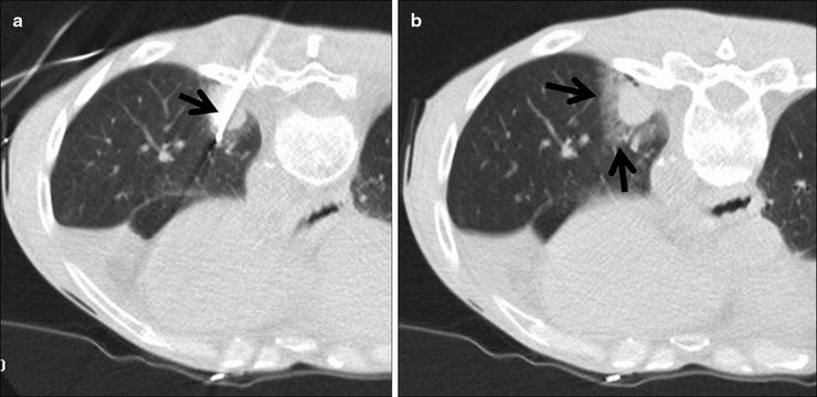

Fig. 52.2
A 60-year-old man with left lower lobe adenocarcinoma felt to be a poor candidate for lobectomy due to underlying lung disease and previous radiotherapy. (a) Axial CT fluoroscopic image shows a cluster RF electrode within the mass. (b) Axial CT fluoroscopic image with the needle removed shows the typical ground-glass halo that surrounds the tumor (arrows).The halo gives a rough indication of energy penetration into the aerated lung around the mass
Once the target lesion is treated, the RF electrodes are removed and CT-guided fluoroscopy is performed to evaluate for a pneumothorax and treat it if needed. All patients are observed 4–6 h in the recovery room, and a repeat chest radiograph is obtained to confirm the absence of a pneumothorax.
Microwave Ablation
Microwave ablation (MWA) like RFA uses heat to coagulate tissue. Electromagnetic microwaves traveling at 9.2 × 10⁸ Hz produce friction and heat by agitating water molecules within the surrounding tissues and causing the molecules to flip. This procedure induces coagulation necrosis and cell death. To maximize the interaction of the water molecules, microwave radiation can specifically be tuned to the natural frequency of water molecules. Temperature is used to measure the amount of heat generated depending on how fast the water molecules oscillate within the target lesion.
Microwave ablation has been successfully utilized in treatment of hepatic malignancies by several groups. Larger tumors (greater than 3 cm) may require the use of multiple MWA applicators to create a large enough area of thermocoagulation. There are currently two MW frequencies (915 and 2,450 mHz) that are available for clinical use. The lower frequency can penetrate deeper into tissue and requires less power. The higher frequency is absorbed more and therefore requires more power. Antenna shaft cooling may not be necessary at 915 mHz but is definitely required at 2,450mHz due to the conduction along the shaft that may lead to thermal damage along the needle tract. Single or multiple MW antennas may be needed to achieve the desired volume of tissue necrosis. Grounding is not necessary with microwave ablation. Unlike RFA, tissue charring is not a significant limitation of electromagnetic wave propagation used in microwave ablation.
Cryoablation (Cryotherapy) Technique
Percutaneous cryoablation (CA) allows gas in a region of constant temperature to travel down the shaft of the cryoprobe through an aperture into an area of lower pressure thereby allowing the gas to expand and become cooler (Joule-Thompson Effect). Argon gas allows expansion from high pressure to low pressure through a constricted orifice (J-T port) within the cryoprobe at ultracold temperatures (approximately −160 °C) and forms an “ice ball” as a marker for identifying the ablative margins. At the end of the procedure, helium gas is used to warm the probe and facilitate removal. Each CA treatment at a given cryoprobe position consists of a 10-min freeze, followed by an 8-min thaw, and subsequently followed by another one 10-min freeze. Faster ablation schemes using a 3-min freeze, 3-min thaw followed by 7-min freeze and thaw, and a final 5-min freeze have been proposed to improve the zone of ablation and slightly shortening the ablation time to 25 min compared to 28 min.
The cryoablation procedure is based on the freeze-thaw-freeze technique, with osmotic shifts causing cellular membrane rupture and eventual cell death. The resulting endothelial damage leads to platelet aggregation and microvascular thrombosis.
Follow-Up
Imaging studies immediately after the procedure and during follow-up are necessary to measure the success or failure of the initial procedure, interval growth and need for repeat ablation, and metachronous tumor development. Unfortunately, at the current time, there is no proven imaging modality or time interval for immediate post-ablation and subsequent imaging to accurately depict success or failure of the initial ablation.
During and immediately after RFA ablation, CT can be used to identify and analyze the tissue changes that occur in the lung around the ablated mass which has been referred to as a ground-glass halo (Fig. 52.2b). This imaging appearance is a very rough approximation of margin of tissue necrosis, and the exact zone of tissue death is somewhere in the middle of this finding. There may be wrinkling of the edges, vaporization, and “cockade phenomenon” which demonstrates concentric rings of varying density. The tumor diameter may decrease or may not change during treatment depending upon tumor type. At 1-month follow-up, the lesion may appear as an area of consolidation and nodularity, and the diameter will be larger than before ablation (Fig. 52.3). There may also be cavitations and “bubbly lucencies.” Successfully treated lung tumor also shows decreased contrast enhancement. PET is also useful in the follow-up evaluation. A decrease or complete absence of FDG activity (photopenia) is suggestive of necrosis with no residual tumor (Fig. 52.3). If there is residual or recurrent tumor, there is increased FDG uptake within the periphery of the lesion. False-positive PET within 6 months can be seen with a pleural reaction (Fig. 52.3). Akeboshi et al. demonstrated that PET was more sensitive than contrast-enhanced CT to detect early tumor progression.
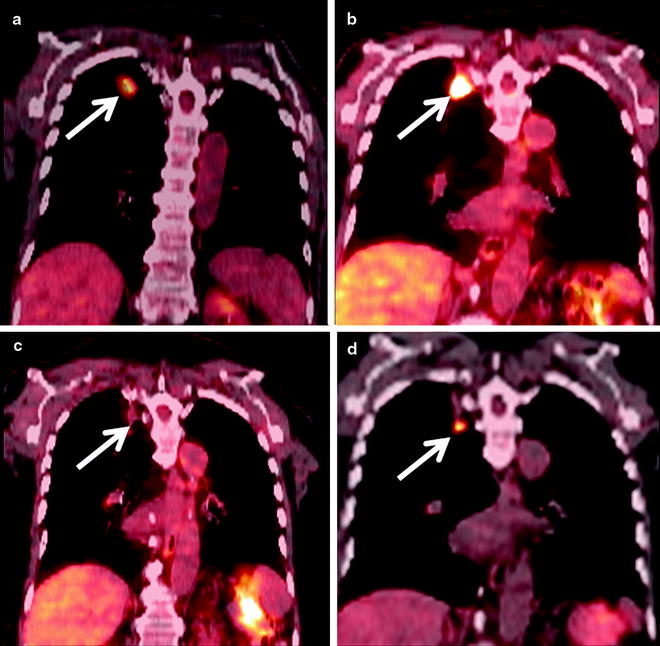

Fig. 52.3
An 84-year-old man with right upper lobe squamous cell carcinoma. (a) Coronal PET/CT shows the FDG-avid cancer in the right upper lobe (arrow). (b) Six months after RFA coronal PET/CT shows extensive FDG-avid pleural-based soft tissue (arrow) which was biopsied and shown to be inflammatory tissue. (c) Repeat PET/CT 1 year after RFA shows interval resolution of FDG activity with the thermal scar (arrow). (d) Eighteen-month follow-up PET/CT shows a new nodule below the ablation scar that is FDG avid (arrow) which was subsequently shown to be recurrent cancer on biopsy
On initial post-ablation contrast-enhanced CT scans, MW ablated tumors demonstrated the effects of thermally induced necrosis. A hazy ground-glass opacification was most common. At 1-, 3-, and 6-month intervals, ablation zones increased in size due to thermal changes in adjacent lung tissue, followed by a persistent reduction in diameter consistent with consolidation. There were also cavitary changes identified (Fig. 52.4). Ablated tumors abutting the visceral pleura resulted in pleural thickening in 34% of ablation zones in 44% of patients or pleural retraction in 5% of ablation zones in 8% of patients.


Fig. 52.4
An 85-year-old woman with 5-cm right lower lobe non-small cell lung cancer was referred for microwave ablation due to poor performance status and dementia. (a) Prone axial CT fluoroscopy image shows two of the four microwave antennae used to treat this cancer. (b) Axial CT image 1 year after the ablation shows internal cavitation of the mass (arrow). (c) Axial CT 52 months after the ablation shows interval shrinkage of the thermal scar and persistent cavitation (arrow)
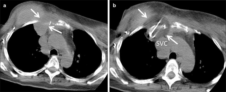
Kawamura et al. report about follow-up CT chest scans of patients who underwent cryoablation (Fig. 52.5) that were carried out at 1-month and then 3-month intervals. Changes in tumor mass after cryoablation were measured according to the Response Evaluation Criteria in Solid Tumors (RECIST) protocol, which is based on objective measurements of lesion size before and after treatment. The response to cryoablation according to RECIST was at the rate of 50%. The response rate of each tumor was 54.3%.
Get Clinical Tree app for offline access

Fig. 52.5
A 60-year-old woman with recurrent breast cancer invading the right anterior chest wall despite chemotherapy and radiation. The patient was referred for palliative cryoablation due to unremitting pain. (a) Axial CT image shows the mass (arrows) extending through the chest wall and abutting the mediastinum. (b) CT image during the freeze cycle shows the low density ice ball (arrows


Stay updated, free articles. Join our Telegram channel

Full access? Get Clinical Tree


