Image-Guided Radiation Therapy
26.1. INTRODUCTION
Broadly, image-guided radiation therapy (IGRT) may be defined as a radiation therapy procedure that uses image guidance at various stages of its process: patient data acquisition, treatment planning, treatment simulation, patient setup, and target localization before and during treatment. In the present context, we will use the term IGRT to signify radiotherapy that uses image guidance procedures for target localization before and during treatment. These procedures use imaging technology to identify and correct problems arising from inter- and intrafractional variations in patient setup and anatomy, including shapes and volumes of treatment target, organs at risk, and surrounding normal tissues. In that context, we will describe a number of image guidance technologies and methods that are available to implement IGRT.
26.2. IGRT IMAGE GUIDANCE TECHNOLOGIES
As the planning target volumes (PTVs) are made increasingly conformal such as in three-dimensional conformal radiotherapy (3-D CRT) and intensity-modulated radiation therapy (IMRT), the accuracy requirements of PTV localization and its dosimetric coverage during each treatment become increasingly stringent. These requirements have propelled advances in the area of dynamic targeting of PTV and visualization of surrounding anatomy before and during treatments. Imaging systems have been developed that are accessible in the treatment room or mounted directly on the linear accelerator. Some of these IGRT-enabling technologies and methods are discussed below.
A. PORTAL AND RADIOGRAPHIC IMAGERS
Modern accelerators (e.g., Varian’s TrueBeam and Elekta’s Versa HD) are equipped with two kinds of imaging systems: (a) kilovoltage x-ray imager in which a conventional x-ray tube is mounted on the gantry with an opposing flat-panel image detector and (b) megavoltage (MV) electronic portal imaging device (EPID) with its own flat-panel image detector. The flat-panel image detector in both cases is a matrix of 256 × 256 solid state detectors consisting of amorphous silicon (a-Si) photodiodes. Operational principles of these imaging devices were discussed in Chapter 12.
Although the kilovoltage (kV) images have better contrast than the MV images of the EPIDs, neither of them is of sufficiently good quality to visualize soft-tissue targets in their entirety. However, kV imagers are quite useful in determining the planned target position in relation to the bony landmarks and/or radio-opaque markers (fiducials) implanted in the target tissues. In addition, the kV imager can be used in both the radiographic and fluoroscopy modes to check patient setup before each treatment or track the movement of fiducial markers due to respiratory motion. The MV imager can provide portal verification before each treatment as well as online monitoring of target position during treatment delivery.
B. IN-ROOM COMPUTED TOMOGRAPHY SCANNER
The kV imaging systems in the radiographic mode provide two-dimensional (2-D) images that are marred by stacked anatomies and therefore do not have the resolution of a computed tomography (CT) scanner. An in-room CT scanner makes it possible to have the capability of obtaining CT images before each treatment. An in-room CT scanner is a conventional CT scanner on rails that is housed in the treatment room and shares the couch with the accelerator (Fig. 26.1).
In order to acquire a pretreatment CT, the couch is rotated into alignment with the CT scanner. The CT scanner on rails is then moved in the axial direction relative to the patient. After acquiring CT scan data, the couch is rotated back into alignment with the accelerator gantry for treatment. Thus, neither the couch nor the patient is moved relative to the treatment isocenter in this process.
In order to acquire a pretreatment CT, the couch is rotated into alignment with the CT scanner. The CT scanner on rails is then moved in the axial direction relative to the patient. After acquiring CT scan data, the couch is rotated back into alignment with the accelerator gantry for treatment. Thus, neither the couch nor the patient is moved relative to the treatment isocenter in this process.
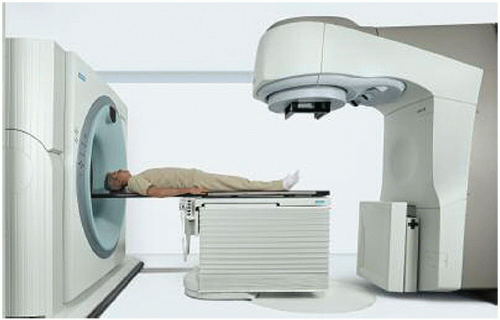 Figure 26.1. Siemen’s CTVision consisting of a Primus linear accelerator and a modified SOMOTOM diagnostic computed tomograph scanner that travels on two parallel rails in the treatment room. (Photograph from www.siemens. com/medical.) |
The advantage of the in-room CT scanner is that it provides high-resolution 3-D volumetric data of patient anatomy in the treatment coordinates. This information is useful not only in target localization prior to treatment, but also in reconstructing dose distribution, which may be compared to the reference treatment plan before each treatment or periodically during the course of radiotherapy. Frequent comparisons of these isodose plans enable one to make setup corrections or modify treatment parameters to minimize variations between the planned and the actual treatment. This procedure falls into the category of what is called the image-guided adaptive radiation therapy (IGART).
C. KILOVOLTAGE CONE-BEAM CT
The on-board kV imaging system is capable of radiography, fluoroscopy, and cone-beam computed tomography (CBCT). The x-ray tube is mounted on a retractable arm at 90 degrees with respect to the central axis of the linear accelerator beam. Image is generated by the flat panel area detectors mounted opposite the x-ray tube. The kilovoltage cone-beam computed tomography (kVCBCT) involves acquiring planar projection images from multiple directions as the gantry is rotated through 180 degrees or more. Three-dimensional volumetric images are reconstructed from these multiple radiographs by the computer, which uses a filtered back-projection algorithm (1).
Ordinarily, the quality of uncorrected reconstructed images would suffer from poor contrast, misregistration, and artifacts, due to problems involving gravity-induced flex in the support arm of the x-ray tube and detector, slight movements of the accelerator gantry during rotation, and the combined effects of beam hardening and x-ray scatter. Corrections on the order of 2 mm are required to compensate for the gravity-induced flex of the support arm and gantry (2). Beam hardening and x-ray scatter cause inaccuracy of CT numbers, contrast reduction, and cupping artifacts.1 These effects are minimized by algorithmic corrections to the computer software (3, 4, 5). The scatter effects can also be minimized by using antiscatter grids, although these result in increased dose to the patient.
By using various corrective measures to offset the effects of flex motions, beam hardening, and scatter, it is possible to achieve cone-beam images with good contrast and submillimeter spatial resolution. Typical resolution employed in the clinical implementation of kVCBCT is about 1 mm voxel size at isocenter. Also, because low-kV x-rays are used in kVCBCT, the images show
reasonably good soft-tissue contrast, which is helpful in verifying or delineating gross tumor volume (GTV).
reasonably good soft-tissue contrast, which is helpful in verifying or delineating gross tumor volume (GTV).
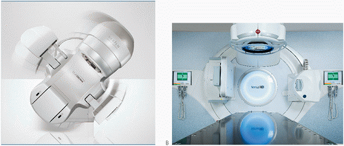 Figure 26.2. A: Varian’s TrueBeam accelerator. (Courtesy of Varian Oncology Systems, Palo Alto, CA.) B: Elekta’s Versa HD unit. (Courtesy of Elekta Inc., Sweden.) Both accelerators are equipped with kilovoltage imaging systems capable of two-dimensional radiography, fluoroscopy, and cone-beam computed tomography modes. |
Currently, kVCBCT technology is offered by both Varian and Elekta. Figure 26.2 shows pictures of Varian’s TrueBeam and Elekta’s Versa HD, both equipped with kVCBCT systems.
D. MEGAVOLTAGE CONE-BEAM CT
Megavoltage cone-beam CT (MVCBCT) is made possible by the use of a traditional EPID with the a-Si flat-panel detector. The x-ray source in this case is the megavoltage therapy beam of the accelerator. Planar projection images are acquired from multiple directions as the x-ray source and the detector rotate about the patient. As in the kVCBCT, 3-D volumetric images are reconstructed by the computer using a filtered back-projection algorithm.
Although the soft-tissue contrast is reduced in the MVCBCT, the images are still good enough for 3-D localization of target position in relation to the bony anatomy and fiducial markers, if implanted in the tumor. The potential advantages of MVCBCT over kVCBCT are as follows:
There is less susceptibility to imaging artifacts due to metallic objects such as hip implants, dental fillings, and surgical clips.
There is no need for extrapolating attenuation coefficients from diagnostic (kV) beams to the therapeutic beam. CT numbers in MVCBCT correlate directly with electron density.
The known dose distribution characteristics of the therapeutic beam allow more accurate calculation of imaging dose in the MVCBCT acquisition process.
Implementation of MVCBCT does not require extensive modification of a linear accelerator that is already equipped with an EPID.
The above advantages, however, should not overshadow the following distinct advantages of kVCBCT over MVCBCT:
Better contrast and spatial resolution
Better soft-tissue visibility at much lower doses
Compatibility of kVCBCT images with the reference treatment plan images for patient setup verification and correction
Combination of radiography, fluoroscopy, and CBCT capabilities from the same source and detector, which provides great flexibility in implementing the goals of IGRT
E. HELICAL TOMOTHERAPY
Helical tomotherapy is an IMRT delivery technique that combines features of a linear accelerator and a helical CT scanner (Chapter 20). The linear accelerator (e.g., 6-MV x-ray beam) is mounted on a CT-like gantry and rotates through a full circle (see Fig. 20.7). Simultaneous with
the gantry rotation, the treatment couch is translated slowly through the doughnut aperture, thus creating a helical motion of the beam with respect to the patient. A computer-controlled multileaf collimator (MLC; a long narrow slit with multiple leaves) provides the required intensity modulation of the beam. The problem of interslice match lines is minimized because of the continuous helical motion of the beam around the longitudinal axis of the patient.
the gantry rotation, the treatment couch is translated slowly through the doughnut aperture, thus creating a helical motion of the beam with respect to the patient. A computer-controlled multileaf collimator (MLC; a long narrow slit with multiple leaves) provides the required intensity modulation of the beam. The problem of interslice match lines is minimized because of the continuous helical motion of the beam around the longitudinal axis of the patient.
The concept of helical tomotherapy was originally proposed by Mackie et al. (6,7) and further developed at the University of Wisconsin (8,9). A commercial tomotherapy unit (HI-ART) is manufactured by TomoTherapy, Inc. (Madison, WI). It can deliver IMRT as well as generate CT images from the same megavoltage x-ray beam as it uses for therapy. That makes helical tomotherapy a unique device capable of delivering both the IMRT and IGRT in the same treatment geometry.
Helical tomotherapy is analogous to conventional helical CT scanning, where the gantry and the couch are in motion simultaneously. The HI-ART’s CT detector is an arc-shaped detector, consisting of 738-channel xenon ion chambers. The source to detector distance is 145 cm and the source to axis distance is 85 cm. A field of view (FOV), which is defined by the width of the multileaf collimator, is 40 cm as projected at the isocenter.
Because tomotherapy images are reconstructed from the same megavoltage x-ray beam as used for actual treatment, they are called MVCT images. Meeks et al. (10) have reported on the MVCT performance characteristics for a HI-ART II tomotherapy unit. Their findings show that, compared to the diagnostic CT images, the noise level in MVCT images is high and the low-contrast resolution is poor. However, in spite of the poor image quality, these relatively low-dose MVCT images (typical scan dose in the range of 1 to 2 cGy) provide sufficient contrast for verifying the patient’s position at the time of treatment. In addition, these images are less susceptible to imaging artifacts caused by high-atomic-number objects such as surgical clips, hip implants, or dental fillings.
Because of the predominance of Compton interactions in the megavoltage range of x-ray energies, the MVCT values are linear with respect to the electron density of the imaged material. Langen et al. (11) have shown that the MVCT numbers are reliable for accurately calculating dose distributions from the MVCT images. In addition, the daily image set may be manually or automatically registered to the treatment-planning image set in order to make adjustments, if needed, to the original treatment plan (12).
F. ULTRASOUND
Principles of ultrasonic imaging were discussed in Chapter 12. It is a noninvasive, nonradiographic real-time imaging technique for localizing soft-tissue structures and tumors, primarily in the abdomen, pelvis, and breast. In IGRT, transabdominal ultrasound systems have been widely used for localizing prostate (13,14). One such system is the Best-NOMOS (Pittsburgh, PA) B-mode Acquisition and Targeting (BAT) system. BAT provides a rapid means of localizing prostate before each treatment and making corrections for interfraction variation of prostate position. Clinical issues in the daily use of this system are discussed in the literature (15,16).
The basic problem with the ultrasound-guided procedures for localizing prostate is the poor image quality. For most observers, ultrasound images have an unfamiliar appearance and are often difficult to interpret. Because of this large inter- and intrauser variability of interpretation, larger planning margins have been recommended (17,18).
Another problem of ultrasound imaging for the prostate is the anatomic distortions caused by the transducer pressure on the abdomen (19). Too much of this pressure could induce a shift in the prostate of as much as 10 mm.
Ordinarily, ultrasound scans generate 2-D images. Their interpretation to visualize 3-D anatomy is difficult and is highly dependent on the skill and expertise of the operator. Three-dimensional ultrasound imaging has been developed to overcome this limitation. One such system is an optically guided 3-D Ultrasound Target Localization system, SonArray, manufactured by Varian Medical Systems (Palo Alto, CA). In this system, 3-D ultrasound data sets are generated through optical tracking of free-hand-acquired 2-D ultrasound images. The operator manipulates the ultrasound probe over the anatomic region of interest to obtain 2-D images, which are automatically transferred to a computer through a video link. The position and angulation of the ultrasound probe are tracked by an array of four infrared light-emitting diodes (IRLEDs). By coupling the ultrasound probe position determined by IRLEDs with the images acquired, a 3-D ultrasound image volume is reconstructed.
A 3-D ultrasound system is definitely an improvement over the traditional 2-D ultrasound systems. However, the basic limitations of the ultrasonic imaging, namely the image quality and the anatomic distortions caused by the transducer pressure, remain. In addition, it is imperative that careful commissioning and quality assurance procedures are followed in the clinical use of these systems (20, 21, 22).
1An artifact in CT images caused by reduction in reconstructed attenuation coefficients due to beam hardening (as near the center of a large object) or by scattered radiation.
26.3. MANAGEMENT OF RESPIRATORY MOTION
Respiratory motion affects all tumor sites in the thorax, abdomen, and pelvis. Tumors in the lung, liver, pancreas, esophagus, breast, kidneys, prostate, and other neighboring sites are known to move due to respiration. Although tumor displacement varies depending on the site and organ location, it is most prevalent and prominent in lung cancers. Studies have shown that lung tumors can move several centimeters in any direction during irradiation. However, the lung tumor motion is independent of tumor size, tumor location, and pulmonary function (23). These and other observations reported in the literature suggest that the tumor motion in lung or other sites cannot be predicted with any degree of accuracy and, therefore, should be assessed individually (24). That means that a real-time tumor-tracking or -gating process is required to manage target motion in radiotherapy.
Management issues of respiratory motion in radiation oncology are discussed at length by the American Association of Physicists in Medicine (AAPM) Task Group 76 (24). The following recommendations are taken from that report:
Respiratory management techniques should be considered if (a) the range of motion is greater than 5 mm in any direction and (b) significant normal tissue sparing can be gained through the use of a respiratory management technique.
If a method of motion measurement is available, an assessment of tumor mobility in three dimensions is essential for treatment planning and delivery of radiation therapy in lung cancer.
If the magnitude of motion is not significant (<5 mm in any direction), the extra effort of using respiratory management is unwarranted.
If a patient-specific tumor motion measurement is made, this information should be used in designing PTV margins in treatment planning. In the absence of a respiratory management device, the entire range of motion should be considered in establishing the PTV margins.
Before deciding on respiratory management, assessment should be made if an individual patient can tolerate the respiratory management technique.
Due to the complexity of the management of the respiratory motion problem, it is essential that the relevant personnel (radiation oncologist, physicist, dosimetrist, and therapist) be well trained in the procedure and be available for participation, assistance, and/or consultation, as needed.
Quality assurance has a crucial role in all aspects of radiation therapy. Institutions should develop and implement quality assurance (QA) procedures as recommended by the AAPM Task Group 40 (25) for the radiotherapy equipment and Task Group 76 (24) specifically for the techniques used in the management of respiratory motion.
Intrafraction motion and its management are an important component of image-guided radiotherapy. Basic principles of some of the methodologies that have been developed for real-time tumor tracking and respiratory management are discussed below. It is indeed an evolving field and it is expected that some of these methodologies will be modified, refined, or discarded as the field develops.
A. FOUR-DIMENSIONAL COMPUTED TOMOGRAPHY
Four-dimensional (4-D) CT is the process of acquiring CT scans synchronously with the patient’s respiratory phases. The 4-D images (the fourth dimension being time) are reconstructed from scans acquired at each respiratory phase of the breathing cycle. Respiration signals are acquired during CT scanning using surrogate signals such as the motion of the abdominal surface, internal anatomy, or volume of air measured by spirometry during inhalation and exhalation cycles. Typically the breathing cycle is divided into ten respiratory phases and multiple CT volumes are taken at each phase. A 4-D CT data set may involve as many as 1,500 CT slices. Details of the 4-D CT methodology are described in the literature (26, 27


Related posts:


Stay updated, free articles. Join our Telegram channel
Full access? Get Clinical Tree
