Fig. 10.7. Path of a detector head in rectilinear scanning of an organ.
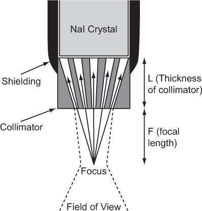
Fig. 10.8. Focusing-type collimator. γ-rays can reach the detector only through the narrow channels as shown by the solid arrows. The field of view of such a collimator (dotted lines) is in general narrow and is narrowest (about 1 cm) in the focal plane. It becomes wider above or below the focal plane.
The detector head assembly consists of a collimator, NaI(Tl) crystal and associated electronics. The collimator used in a rectilinear scanner is known as a multihole focusing type collimator and is shown in Figure 10.8. It consists of a lead cylinder with a number of tapered holes formed to converge at a single point outside the collimator, known as the focus. The information gathered by the detector head regarding the amount of radioactivity at a given location is continuously relayed to a photographic system, where a small cathode-ray tube, with a fast phosphor screen and well-collimated light spot that exposes an x-ray film, is moved in a light-tight box in synchronization with the detector head. At the completion of the scan, the x-ray film is developed portraying the distribution of radioactivity in the organ.
Key Points
1. Three problems, collimation, attenuation, and Compton scattering, make in vivo detection of radiation difficult.
2. Collimation is needed to exclude detection of radiation emitted outside the area of interest. FOV of a collimator is determined by the size of the area of interest. FOV is related to the resolution and sensitivity of a collimator. Collimators are primarily made of lead, an inexpensive, high–atomic-number, and high-density material.
3. Compton scattering in the FOV of a collimator of γ-rays emitted outside the FOV allows some γ-rays to be detected from outside the FOV. The scattered radiation can be reduced (but not eliminated) with a narrow window set on the primary γ-ray energy in a NaI(Tl) detector.
4. Other methods of reducing the contribution of scattered γ-rays in a clinical situation use two or three windows as described in the text.
5. Attenuation by the overlying tissue is the main source of error in quantification of radioactivity in vivo. In routine imaging, this is taken into consideration while interpreting the images.
6. Organ uptake probes are used to determine radioactivity in a whole organ (e.g., thyroid). Miniature uptake probes are used during surgery to detect small lesions.
7. Rectilinear scanners were the earliest instruments to determine the radioactive distribution within an organ. However, their inability to detect the radionuclidic distributions at a fast rate made them obsolete.
Questions
1. List the problems that make quantification of in vivo radioactivity difficult.
2. How does pulse-height analysis help in the detection of in vivo radioactivity?
3. What is the ideal detector from the scatter rejection point of view?
4. What is the effect of narrowing the PHA window on the scattered counts and the sensitivity of a NaI detector?
5. Attenuation is a problem in in vivo detection of radioactivity. Which of the following organs poses the most challenge in this regard: brain, heart, or kidneys?
6. How does one obtain a geometric mean image?
7. What is the primary function of a collimator? Why are collimators made of lead? Can other materials be used instead of lead?
8. Why is there an optimum range of distance between the patient’s thyroid and the probe when measuring the radioiodine uptake?
9. What are miniature surgical probes are used for?
10. Why is the rectilinear scanner no longer in clinical use?
A gamma camera, in particular a scintillation camera, occupies a central place in every nuclear medicine department. In a gamma camera, as opposed to a rectilinear scanner where an organ is scanned point by point, the whole organ or a large part of the body is imaged simultaneously. In this respect, a gamma camera behaves similarly to a photographic camera, although the two types of cameras are entirely different in construction and operation. Unlike light rays, x- or γ-rays cannot be reflected or refracted by using mirrors, lenses, or prisms. Therefore, the general principles of light photography cannot be applied to imaging of objects emitting x- or γ-rays. Instead, the selective attenuation and transmission of x- and γ-rays by different materials, such as lead and air, forms the basis of imaging with a gamma camera.
The simultaneous visualization of an entire organ or organs by a gamma camera is its single most important quality that made rectilinear scanners obsolete. This feature makes the study of rapid dynamic processes possible. Dynamic studies with 10 to 20 images/s are now routinely obtained to determine cardiac output and ejection fraction.
Of a variety of approaches attempted in research laboratories for the development of gamma cameras, the scintillation camera developed by Anger has emerged as a superior choice in clinical nuclear medicine. Since its commercial introduction in 1966, the modem scintillation camera has gone through several waves of technologic innovations, from improved photomultiplier (PM) tubes and collimators, nonuniformity correction modules, to all digital cameras of the present. It is now almost a new instrument. The only constant element is the scintillator material, which is still a NaI(Tl) crystal. However, CZT detector with further improvement is a serious threat to NaI(Tl) detector. Dedicated gamma camera using CZT detectors for small field of view for cardiac studies (discussed in Chapter 14) and mammography using radiopharmaceuticals (LumaGem) are already available.
Scintillation Camera
In a scintillation camera, a large disc- or rectangular-shaped NaI(Tl) crystal is viewed from one side by an array of PM tubes. Such an array of PM tubes not only determines the total amount of light produced by a γ-ray interaction, as is common in a scintillator detector and discussed in Chapter 8, but also the location of light production in the crystal. The other side of the crystal is attached to a collimator that acts like a lens of a photo camera.
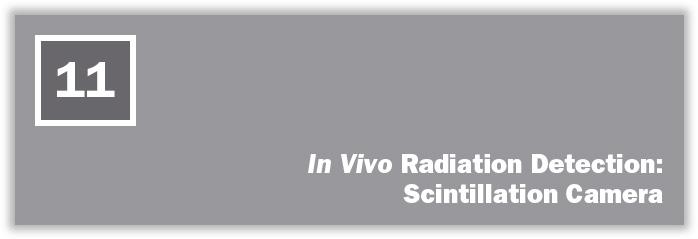
Physically, a scintillation camera is divided in two parts. The detector head contains the collimator and the NaI(Tl) crystal with PM tubes and associated electronics and is mounted on a stand where it can be easily moved up or down or rotated in any desired position with handheld controls or automatically under the direction of a computer (Fig. 11.1). Recently, two or even three detector heads have become popular, particularly with single-photon emission computed tomography (SPECT, Chapter 14). Increased geometric efficiency is the obvious advantage of multiple detector heads. The second part is the console, which houses the power supplies and operational controls of the scintillation camera, including the display module and quite often an integrated digital computer. In portable scintillation cameras, the detector head and console are joined together in one unit so that it can be moved from one location to another without too much difficulty.
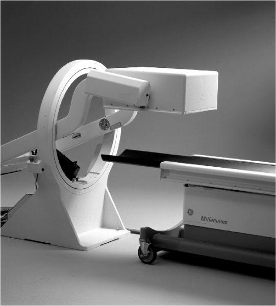
Fig. 11.1. A single head detector mounted on a stand. It can be easily positioned for imaging at any angle to a patient lying on the bed. (From General Electric, with permission.)
Operationally, a scintillation camera consists of four basic parts (Fig. 11.2, A–D): collimator, detector, multiple PM tubes and position (x, y coordinates) determining circuit, and display. Here, I describe the workings of a scintillation camera. Its operating characteristics such as spatial resolution, sensitivity, and uniformity and quality control are discussed in Chapter 12.
Collimators The purpose of a collimator in a scintillation camera is to allow x- or γ-rays originating from a selected area of an organ to reach a selected area of the detector. Thus, a collimator establishes a one-to-one correspondence between different locations on the detector and those within the organ. Another feature of a scintillation camera collimator is that its field of view is large enough to encompass completely the total organ or the desired part of the body to be imaged. Four types of collimators have been used with scintillation cameras (Fig. 11.3).
Parallel Hole A parallel-hole collimator is made of a large number (many thousands) of small holes in a lead disc. The diameter of the lead disc is the same as that of the scintillation crystal used. Thickness of the lead disc and the diameter of the holes depend on the desired spatial resolution and sensitivity of these collimators (discussed in Chapter 12). Lead walls between the holes, called septa, for a well-designed collimator, absorb most, if not all, radiation incident on them. Holes are axial, parallel to each other and circular or hexagonal in shape.
Fig. 11.2. Schematics of a typical scintillation camera. Four operational components are identified: A (collimator), B (NaI crystal), C (light pipe, PM tubes, and preamplifiers), and D (CRT for display). Detector head incorporates in it A, B, and C, and the console contains D and power supplies and associated electronics.
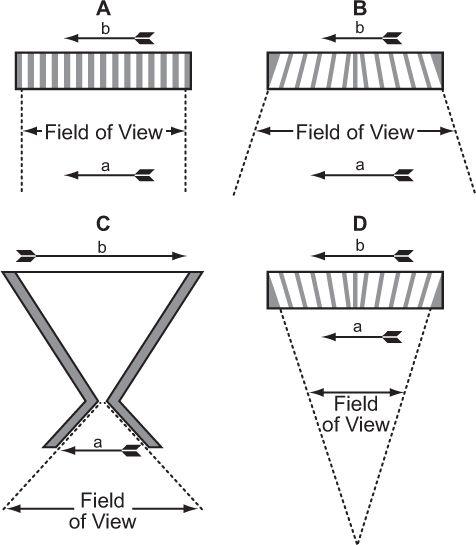
Fig. 11.3. Collimators used in a scintillation camera. (A) Parallel-hole collimator: The object a projects the same size image b on the crystal face. The field of view of such a collimator does not vary significantly with distance from the collimator. (B) Diverging collimator: The size of the image b is smaller than the size of the object a, and the field of view increases as we move away from the collimator. (C) Pinhole collimator: A magnified or minified image b of an object a, is produced, depending on its distance from the pinhole. The field of view of a pinhole increases rapidly as we move away from the pinhole. (D) Converging collimator: This collimator produces a magnified image b of an object a. The field of view decreases as we move away from the detector. A converging collimator provides the optimum sensitivity and spatial resolution for an object that is smaller than the crystal size used in the scintillation camera.
Pinhole A pinhole collimator consists of a single hole, about 5 mm in diameter, at the top of a hollow lead cone. The diameter at the base of the lead cone is the size of the NaI(Tl) crystal. The top of the cone faces the patient. The height of the cone can range from 12 to 20 inches.
Converging A converging collimator is similar to a parallel-hole collimator except that the holes, as we move away from the center of the collimator toward the edge of the collimator, start tilting toward the center, as shown in Figure 11.3. Outermost holes have the most tilt. All holes focus at an axial point, outside the collimator (typically 10–20 inches) and toward the radioactive source or the patient.
Diverging In a diverging collimator, the tilt of the holes is away from the center. As a result, these holes converge toward the detector. In fact, if one flips over a converging collimator, it becomes a diverging collimator and vice versa.
As can be seen, in all these collimators, γ-rays originating from one area of the arrow reach only a selected area on the crystal. Thus, γ-rays originating from the front of the arrow reach a different location on the crystal than γ-rays originating from the middle or back of the arrow. The size of the image formed on the crystal depends on the type of collimator and distance of the object (arrow) from the collimator. In the case of a pinhole collimator, the image is also inverted. The choice of a particular type of collimator is basically dictated by the size of the organ to be imaged. For imaging organs that are similar in size to the size of the detector [NaI(Tl)] crystal, parallel-hole collimators provide the best sensitivity and spatial resolution. For organs larger than the size of the crystal, diverging collimators are preferred. For organs smaller than the size of the crystal, converging collimators have shown great merit. When the size of the organ is small, such as the thyroid, a pinhole collimator is the collimator of choice. One problem that makes the use of pinhole, converging, or diverging collimators less satisfactory than parallel-hole collimators is the fact that for three-dimensional objects (which all organs are), the different planes of the object (front, back, or middle of the organ) are magnified or minified to different degrees by these collimators. This produces distortions in the image that under most clinical circumstances are unacceptable.
Commercially, the collimators, besides being characterized by the above four types, are also classified according to their spatial resolution or sensitivity as high-sensitivity (for dynamic studies), all purpose (for most clinical applications), or high-spatial-resolution (for fine details) collimators and according to the energies of γ-rays for which they have been optimized as low-energy (0–200 keV), medium-energy (200–400 keV), and high-energy (400–600 keV) collimators. High-energy collimators are used sometimes with positron-emitting radionuclides, as discussed in Chapter 14. The main difference between collimators designed for different energies is the thickness of septum that increases with energy.
Detector, NaI(Tl) Crystal
Size and Thickness As has already been pointed out, the basic detector element in a scintillation camera is a large disc-shaped [NaI(Tl)] crystal that is viewed from one side by a large number of PM tubes. The diameter of the crystal varies from 11 to 20 inches. Eleven-inch-diameter crystals are used in the standard scintillation camera, whereas 16- to 20-inch-diameter crystals are used in so-called large field of view (LFOV) scintillation cameras. The main advantage of a large crystal is the increased sensitivity for large organs such as lungs or the whole body. For a more effective use of the crystal area, rectangular crystals are also available in some scintillation cameras. The thickness of the crystal is generally 1/2 inch, but scintillation cameras with 3/8- or 1/4-inch-thick crystals are also in vogue, particularly for nuclear cardiology work. Reduced thickness of the crystal improves the intrinsic spatial resolution (to be defined in the next section). The trade-off for improved intrinsic spatial resolution is the reduction in intrinsic sensitivity, particularly for higher energy (>150 keV) γ-rays.
Energy Selection The detection and measurement of energy of the γ-rays passing through the collimator is performed as in any NaI(Tl) detector system, except that in scintillation cameras a large number of PM tubes are used instead of a single PM tube. To determine the energy of a γ-ray, one has to determine the total amount of light produced in the crystal (Chapter 8, p. 84). In a scintillation camera, the total light produced is distributed among many or all PM tubes. Therefore, to determine the total amount of light produced, the outputs of all PM tubes have to be summed to produce a pulse equivalent to that produced in a simple NaI(Tl) detector (with only one PM tube). The summated pulse is known as the Z pulse (a misnomer as this should be called E pulse). Pulse-height analysis on Z pulses allows us to select the pulses of the desired energy.
Two important attributes of the Z pulse are linearity with γ-ray energy and its spatial independence (Z pulse-height should not depend on the location of the point of light production in the crystal). On both scores, newer scintillation cameras have improved significantly. The remainder of the nonlinearity and spatial dependence is reduced further by using online correction methods, as discussed in Chapter 12. Summation of pulses from many PM tubes to obtain a Z pulse in a scintillation camera makes its energy resolution slightly worse than a simple NaI(Tl) detector.
Like any other NaI(Tl) detector, in a scintillation camera there are four controls related to the detection of γ-rays and their energies: high voltage, gain of the amplifier, peak energy E, and window width ΔE or %ΔE. Energy selection is usually automated; to choose a γ-ray of a particular energy, one presses a designated button and appropriate pulses are automatically selected. Another useful feature is a provision for simultaneous selection of two or even three γ-rays of different energies. This feature requires two or three pulse-height analyzers (PHAs) and is useful for imaging the distribution of radionuclides that emit more than one γ-ray (e.g., 67Ga, 111In, or even 201Tl) or for rejecting the scattered radiation as was pointed out previously (p. 104).
Automatic Peak Tracking Scintillation detectors are prone to slow drifts in their outputs, mainly due to the changes in the gain of a PM tube. Changes in the PM gain are caused by small ambient temperature and high-voltage fluctuations. In newer cameras, electronic circuits have been provided that monitor these drifts and readjust the high voltage or amplifier gain to its original value. The automatic peak tracking circuits track the PM gains either on demand or continuously, depending on the manufacturer of a scintillation camera. In either case, the output of PM tubes, and therefore the stability of the scintillation camera itself, has improved tremendously.
Counting Pulses selected by the PHA, besides being sent to a logic circuit for generation of X and Y pulses as discussed in the next section, are fed into a counter-timer module. The scintillation camera can count either for a fixed-time interval (preselected time) or for an assigned number of counts (preselected counts). There is also a provision for imaging to stop at preselected time intervals or a preselected number of counts, depending on which happens first. A manual control allows one to start or stop counting at any time. Another feature found only in some scintillation cameras is preselection of the information density in a given area of the image. The scintillation camera will stop when a preselected number of counts have been acquired in the desired area of the image. Scintillation cameras interfaced or integrated with digital computers have these functions—start, stop, time, or number of counts—under computer control.
Position Determining Circuit (x, y Coordinates)
Pulse-Height Distribution Among PM Tubes A collimator in a scintillation camera allows γ or x rays originating from one small part of an organ to reach a small part of the crystal in a one-to-one correspondence. To keep this correspondence intact electronically, we should know where the γ rays are interacting in the crystal. This is accomplished with the help of a large number (commonly 37 or 67) of PM tubes, but in Figure 11.4, it is illustrated by considering a simple array of seven PM tubes. In this case, when light is produced at point a in the crystal, it is distributed among all seven PM tubes. However, PM tube 3, being closest to the point a, receives the maximum amount of light. Similarly, when light is produced at other points in the crystal, different PM tubes will receive the maximum amount of light. Thus, by knowing which PM tube received the maximum amount of light, it is possible to know the rough location (near the PM tube receiving the maximum amount of light) of the point of light production. To locate the point of light production more accurately, the amount of light received by each PM tube, rather than the one receiving the most light, has to be taken into account (i.e., the distribution of light among different PM tubes and therefore the pulse-height distribution produced by the PM tubes is considered). The distribution of light or the pulse heights produced among different PM tubes are directly proportional to the solid angle subtended by each PM tube at the point of light production. This fact is used in the determination of the exact location of the point of light production. The PM tubes can be either a circular or hexagonal cross section. A hexagonal cross section has the advantage of close packing and therefore less dead space between the PM tubes (Fig. 11.4).
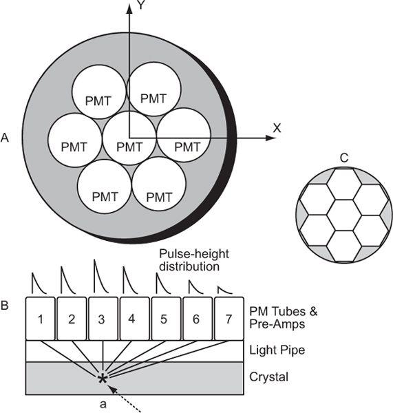
Fig. 11.4. Geometric arrangement of PM tubes to localize the point of light- production in a scintillation camera (A). When a γ-ray interacts at point a in the crystal (B), PM tube 3 receives the maximum amount of light, thus providing the appropriate location of the point at which the light is produced. For a γ-ray interaction at a different point, another PM tube will receive the most light. By knowing the PM tube that receives the maximum amount, one can approximately locate the point of light production. However, for more accurate localization, we have to consider the pulse-height distribution produced among many PM tubes. C The shape of PM tubes does not have to be circular; a hexagonal shape is better because of fuller coverage of the crystal area. The same argument is true for the shape of the holes of a collimator where hexagonal-shaped holes are also preferred over circular-shaped holes.
X and Y Pulses, and Z pulse The output of a PM tube is analog, and it was as such used by Anger to produce two position-determining analog pulses, X and Y and the energy analog pulse, Z. However, in present-day scintillation cameras, the output of each PM tube is digitized (digitization is explained later in this chapter under interfacing with a computer) and all subsequent processing is done with a microcomputer to produce, in digital form, the two position-localizing pulses, X and Y, and the energy pulse Z.
To determine the position-localizing pulses, in analog or digital version, the outputs of various PM tubes are summed with appropriate “weighting factors” (these depend on the distance of the PM tube from the center of the crystal and are not relevant here) to yield four analog signals, known as X+, X−, Y+, and Y−. In commercial scintillation cameras, the number of PM tubes varies from 19 to 96, and the summation circuits are complex and differ from one manufacturer to another.
The position-defining voltages X and Y and the energy-defining Z pulse discussed earlier are generated from the four voltages X+, X−, Y+, and Y− as follows:


where K is a constant.
The most desirable property of the X and Y pulses is their linearity with distance of the point of light production along the x or y axis from the center of the crystal. The farther the distance (x, y coordinate) of the source of light from the center of the crystal, the higher the pulse heights, X and Y. However, because of the geometry of light collection, these pulses are not as linear with distance as one would like them to be. Use of light pipe as shown in Figure 11.4 or nonlinear pulse shaping, are two common methods to improve the linearity of X and Y pulses. These methods do not remove the nonlinearity completely. The residual nonlinearity has to be measured and corrected online, as discussed in Chapter 12.
To display the γ-ray interaction, X and Y pulses (if digital, these have to be converted back into analog form) are used to deflect a light spot on a cathode-ray tube (CRT) or oscilloscope in direct proportion to the amplitude (magnitude) of X and Y. The final image of the distribution is formed from the oscilloscope as discussed under display. If a digital computer is used, this information (X- and Y-pulse amplitudes) is stored in memory for further processing or later display.
Intrinsic Spatial Resolution Even after considering the amount of light received by all PM tubes and making all the corrections, there is always a small error involved in the exact localization of the point of light production. This error is a measure of the intrinsic spatial resolution of the scintillation camera. Intrinsic spatial resolution is a complex function of the thickness of the crystal, the number of PM tubes used for position determination, the type and shape of PM tubes, and the thickness of light pipe, if used, to couple the PM tubes with the crystal. The most important of these is the thickness of the crystal. Reducing the thickness of the crystal improves the intrinsic spatial resolution, but it also decreases sensitivity of a scintillation camera as a lesser number of γ-rays interact in the crystal. Therefore, a compromise has to be made between the intrinsic spatial resolution and sensitivity of the scintillation camera. The optimum range of thickness for scintillation cameras is 3/8 to 1/2 inches for 140-keV γ-rays. Another factor that also affects intrinsic spatial resolution of the scintillation camera is the energy of γ-rays. This is due to the fact that a higher energy γ-ray produces more light in the crystal (for photo-electric events that are always selected) than a lower energy γ-ray. More light enables better localization of the point of γ-ray interaction, and better localization means better intrinsic spatial resolution. Its exact relationship is shown in the next chapter.
Display Gamma-rays originating in the field of view of a collimator interact in the crystal at different locations. These interactions in general occur in a random fashion. A display device should be able to portray such a randomly generated position information (X, Y) quickly (at least 106 events per minute) and accurately. A CRT or an oscilloscope, of which a CRT is an integral part, is effectively used for this purpose.
Cathode-Ray Tube A CRT is an evacuated glass tube consisting of five basic components: an electron gun, a focusing electrode, a set of horizontal deflection plates (x direction), a set of vertical deflection plates (y direction), and a phosphor screen. These are shown schematically in Figure 11.5. The electron gun produces a stream of fast electrons. The number of electrons or the intensity of the electron stream can be varied, if desired, by intensity control I. The focusing electrode allows focusing the electron stream to a narrow circular beam (about 0.1 mm in diameter). When voltage pulses are applied to the horizontal and vertical plates, the electron beam moves in the x and y directions in direct proportion to the magnitude of the voltage pulses applied at the horizontal and vertical plates, respectively. The duration for which the electron beam stays at its new location depends on the duration of the voltage pulses applied to the horizontal and vertical plates. It is generally less than a microsecond. When there is no voltage pulse applied to the horizontal and vertical plates, the electron beam remains at the center of the phosphor screen. The location of the electron beam on the screen is made visible by the phosphor that emits light at the point where the electron beam strikes it. In this way, when voltage pulses of different magnitudes are applied in succession to the horizontal and vertical plates, the light spot on the CRT screen moves from one place to another but always at a distance that is directly proportional to the magnitude of the applied voltage pulses. The intensity of the light spot is controlled by the intensity control I.
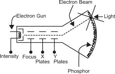
Fig. 11.5. Simplified schematic of a cathode-ray tube (CRT).
Display of Individual Interactions For displaying position information from the scintillation detector, the X and Y voltage pulses are applied to the horizontal and vertical plates of a CRT. The Z signal that carries the energy information exercises a veto on the X and Y signals in such a manner that these are applied to the CRT horizontal and vertical plates only if the Z signal is within the energy range selected by the PHA. If the Z pulses are outside the range selected by PHA, then X and Y are not applied to the CRT horizontal and vertical plates. Thus, only those γ-ray interactions that deposit energy in the crystal in the range selected by PHA are displayed on the CRT screen.
In summary, the display functions as follows. A γ-ray interacts in the detector and the detector produces three signals, giving the location (X and Y pulses) of the γ-ray interaction and the energy transfer (Z pulse) by the γ-ray interaction. The Z pulse is analyzed, and if it is within the selected range, the position signals (X and Y pulses) are applied to the CRT plates, which deflect the light spot from the center of the screen to a distance proportional to the X and Y voltages. When a new γ-ray interacts in the crystal, a new set of X, Y, and Z signals is produced that then deflects the light spot to a new location given by these signals. In this way, as more and more γ-rays interact in the crystal, the light spot on the CRT screen keeps moving from one place to another in correspondence with the location of γ-ray interaction in the crystal up to 500,000 times or more in a typical image (Fig. 11.6). Because the usual size of CRTs range from 3 to 5 inches in diameter, the image on the CRT screen is displayed in a smaller size than the actual size of the organ or part of the body imaged.
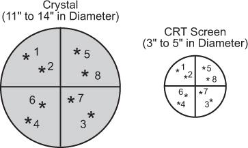
Fig. 11.6. Direct correspondence of the location of γ-ray interaction in scintillation detector with the location of light spot on CRT screen.
Integration on a Film A flying light spot on the screen of a CRT does not constitute an image. This image is formed by point-by-point integration of this information on a photographic film.
Film Characteristics On a film, darker areas represent more radioactivity, whereas lighter areas represent less activity. Film darkening is quantitatively measured by a parameter known as optical density or, simply, density. It is defined as the logarithm (base 10) of the ratio of the intensity of incident light on the film to the intensity of the light transmitted by the film. According to this definition, an area of the film with a density of 2 will transmit only 1% light and will therefore appear almost black to the naked eye. A density of 0 represents 100% transmission; therefore, an area with density of zero will appear white. Densities between 0 and 2 will appear as shades of gray. The relationship of density to exposure for a typical x-ray film is shown in Figure 11.7. This curve is known as the H-D curve of the film. The average slope between points A and B determines the contrast of a film, and the relative log exposure between the points A and B (horizontal distance) determines the latitude of a film. A high-contrast film displays smaller exposure variations than a low-contrast film, but a high-contrast film has smaller latitude. Therefore, the range of exposures that can be displayed on a high-contrast film is smaller (Fig. 11.7).
Film Exposure It can be seen from the H-D curve that the density is dependent on the exposure or the count rate only in the region that lies between points A and B marked on the curves. The trick in photo display is to correspond this region to the range of the count rates that is of most interest. Normally, count rates in an organ may vary from zero to a maximum Rmax for effective display, Rmax (also known as the “hot spot”) should correspond to point B and zero count rate to point A on the H-D curve. The Rmax for individual patients differs because of variations in the administered radiopharmaceutical dose, localization and distribution in the organ, and the size and shape of the organ. Some variations are taken care of when one uses fixed number of counts rather than fixed amount of time for exposure. The proper exposure of the film, which is controlled by the intensity I of the CRT, is inversely related to the number of counts. The more counts in an image, the lower setting of I needed and vice versa. Generally, a table is made for the number of counts in an image and I setting needed for proper exposure for those counts.
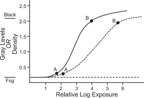
Fig. 11.7. Typical H-D curves of x-ray films used to display information. For the proper display of count rate information, the maximum count rate (hot spot) should correspond to point B and the minimum count rate to point A. Two types of films are shown: solid curve, film with high contrast and small latitude; broken curve, film with low contrast and large latitude.
In fast dynamic studies where the exposure is for a fixed time, I settings are only a guess. This quite often produces bad results. The only solution to this problem is to interface the scintillation camera with a computer, store images, and make exposures after the number of counts in each image has been determined.
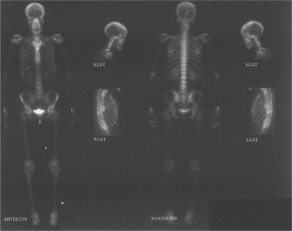
Multiformat Recording A multiformat recording system is commonly used in nuclear medicine. In this system, multiple images are recorded on a single sheet of x-ray film, usually 8 × 10 or 11 × 14 inches in size. The number of images and therefore the size of the image that can be recorded on a single sheet can be varied easily with the help of controls provided for such purposes. Thus, a single sheet may contain from one to as many as 64 images. The main advantage of this device is that all views from one patient, including dynamic studies, can be recorded on a single sheet of film, thus consolidating most of the information in one place. A typical study, a bone scan using this format, is shown in Figure 11.8.
Imaging with a Scintillation Camera
Generally, the following steps are taken to obtain an image with a scintillation camera:
1. Selection of the study to be performed (e.g., brain, liver, etc.);
2. Selection of the radiopharmaceutical and the dose of radiopharmaceutical. A radio-pharmaceutical is generally administered to patients away from the scintillation camera, but sometimes, particularly when fast dynamic studies are to be performed, it may have to be administered with the patient in the appropriate position under the camera (step 7);
3. Selection of the PHA parameters (peak energy and % window corresponding to the γ-ray emitted by the radionuclide to be used);
4. Selection of an appropriate collimator (with respect to energy and spatial resolution);
5. Selection of the mode: accumulation of a certain number of counts or exposure for fixed amount of time;
6. Selection of the appropriate intensity of the CRT for the number of counts expected or to be acquired in the image;
7. Positioning of the patient under the camera and, if the radiopharmaceutical has not been administered, administration of the radiopharmaceutical;
8. Start and finish of the exposure;
9. Development of the film. If more than one view is to be displayed on the same film, then the development of the film takes place at the end of the study.
Related posts:


Stay updated, free articles. Join our Telegram channel

Full access? Get Clinical Tree


