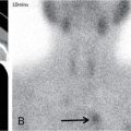
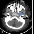
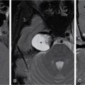
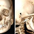
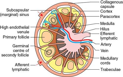
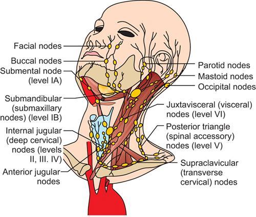
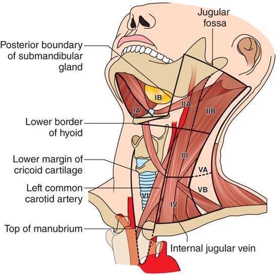
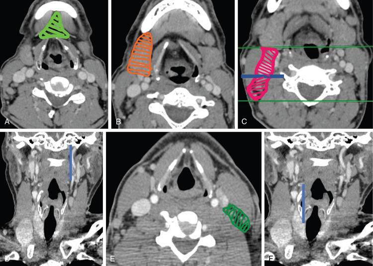
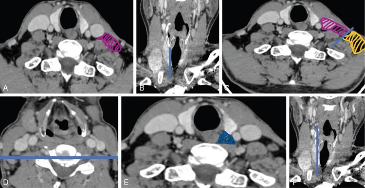
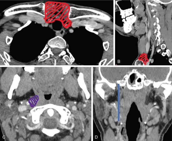
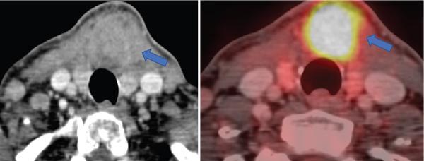
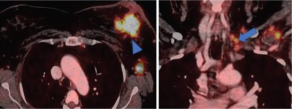
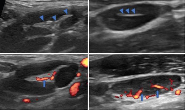
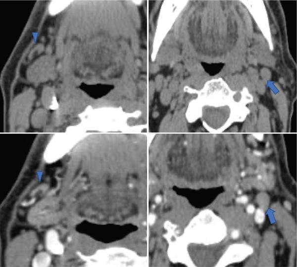
Diva Shah, Abhishek Mahajan, Arpita Sahu Evaluation of cervical lymph nodes is very challenging for both radiologist and head neck specialist. It requires in-depth understanding of neck anatomy with the ability to differentiate between normal and abnormal morphological appearance, including variations in size and shape, image-based classification and various drainage pathways. Clinical correlation is the basis of image interpretation using any modality. With the advent of various imaging advances and aspiration cytology/biopsy techniques under image guidance, it is possible to assess the lymph node pathology accurately. USG, CT, MRI and PET-CT scans provide complementary information to the overall assessment of patients. This chapter covers the basic anatomy of head and neck lymph node stations and its associated pathologies. Posttreatment imaging and PET-CT are covered in a different chapter. Jugular lymph sac is the first sac to develop at the junction of jugular and subclavian veins during fifth week of embryonic life. It spreads lymphatic capillary plexus to thorax, upper limbs and head and neck along the major veins. Lymph node is a bean-shaped structure and part of the lymphatic system. An average length of node ranges from 10 to 20 mm. It is enclosed within a capsule with medial depression called “hilum” where the nodal artery, vein and the efferent lymphatic vessel enter and exit (Fig. 3.21.1). The lymphatic drainage of the head and neck is unique. The head and neck region contains a rich and extensive lymphatic network of more than 300 nodes which constitutes more than 40% of lymph nodes of the human body. Lymph nodes are arranged in two horizontal rings and two vertical chains on either side of neck (Fig. 3.21.2). Head and neck lymph nodes can be classified based primarily on anatomic location (such as groups and chains) or using the American Joint Committee on Cancer’s (AJCC) criteria. The CT and MRI techniques are the basis of such classification using precise anatomical landmarks classifying the nodal levels for comparison and reproducibility. Familiarity with this classification system is essential for both radiologists and clinicians. Image-based classification is done in axial plane on cross-sectional imaging with neutral head position, from skull base to the manubrium. To evaluate thyroid and subglottic laryngeal cancers, the caudal margin should be extended down to the level of carina. The hard palate should be perpendicular to the tabletop position, and the shoulder should be down as far as possible. The anatomical landmarks for image-based classification include the following (Fig. 3.21.3): While using the classification, each side of neck should be evaluated separately. The lines used to define the boundaries of the levels on each side of the neck should be drawn or visualized as an imaginary line from anatomical landmarks on cross-sectional imaging. When a lymph node lies on a junctional area between two levels, the level at which most of the nodal cross-sectional area lies is considered to classify the level of node (Figs 3.21.4–3.21.6 and Table 3.21.1). The supraclavicular fossa (also known as Ho’s triangle) includes level IV and V nodes, and it is difficult to interpret precisely only on axial plane. If a node is located below the clavicle level and lateral to ribs, it is considered a deep axillary node. CT scan axial sections with coronal reformatted CT images help in accurate determination of nodal location. Level II node, also known as jugulodigastric (upper deep cervical) node, drains tonsils and oropharynx. Exposure to microorganisms to this node is highest, and hence, they tend to be larger than any other head and neck nodes. Few nodal stations are referred to their classic anatomic names, e.g. buccal, parotid, occipital and retropharyngeal nodes. Retropharyngeal nodes are located medial to internal carotid artery from skull base to superior margin of hyoid bone. The nodes lying in the central compartment in midline of neck anterior to the cricothyroid membrane, are known as “Delphian nodes” (Fig. 3.21.7). They can harbor metastasis in tumors of anterior commissure or subglottis or thyroid gland. Most inferior and transverse deep cervical chain nodes on the left side include supraclavicular nodes located anatomically at the junction of thoracic duct and left subclavian vein, also known as Virchow’s node or Troisier/Signal nodes (Fig. 3.21.8). These nodes can harbor metastasis from infraclavicular pathology such as abdominal and thoracic malignancies, particularly from carcinoma of lung, breast, oesophagus and gastric cancers. A normal cervical node on USG appears as a bean-shaped, smoothly marginated with echogenic fatty hilum situated either centrally or eccentrically with central or eccentric vascularity (Fig. 3.21.9). On CT scan, it appears isodense to adjacent muscle with lucent fatty hilum. It enhances similarly or slightly more than adjacent muscles on postcontrast images (Fig. 3.21.10). On MRI, the node appears isointense to muscle on T1W images, hyperintense on T2W and STIR images. A high-frequency transducer has great spatial resolution and is superior for morphological and architectural evaluation of node than any other modality. It also aids in doing guided procedures. USG-guided FNAC/biopsy is the most useful tool in the assessment of indeterminate nodes. Doppler assessment is an important adjuvant tool for evaluating internal vascularity and pattern of vascularity within the node. Hilar vascularity is the most common pattern for a reactive node. Pathological node can be avascular or show peripheral pattern due to presence of neovascularity in cortex or subcapsular region. Major limitation of ultrasonography is that it is operator-dependent with a steep learning curve. It cannot evaluate deep nodes (retropharyngeal) and detailed nodal staging in cancer workup. Multidetector computed tomography (MDCT) is a choice of imaging for most head and neck nodal evaluation with suspected primary head and neck cancers or patients with cervical lymphadenopathy of unknown origin. CT scan is faster and overcomes breathing and swallowing artefacts and gives information about nodal site, size, morphological changes and other associated findings. MRI has the advantage of nonionizing radiation and excellent contrast resolution. It is preferable in staging and postneoadjuvant chemotherapy follow-up/response evaluation of nasopharyngeal, tongue and oropharyngeal malignancy. The presence of intranodal necrosis or inhomogeneous signal on T2W images is regarded as the most reliable signs of neck node metastasis. However, nonnecrotic metastatic node shows similar signal as a reactive node. In such cases, one cannot rely on signal intensity criteria alone. Several studies have reported the efficacy of advanced MRI sequences, including DWI, in detection of a metastatic node. A metastatic node shows significantly low ADC value due to densely packed cell and increased nuclear–cytoplasmic ratio in tumour cells. A systematic approach and imaging evaluation are required for evaluation of head and neck nodes. It is essential to know the pattern of lymphatic drainage, common imaging criteria and various imaging pitfalls for diagnosing pathological nodes. Five-step patterns of approach for evaluation of neck node, remembered by using mnemonic SPSES (Table 3.21.2).
3.21: Imaging in head and neck lymphnodes
Abbreviation
Anatomy
Nodal classification, technique and approach to image interpretation
Basic imaging modalities
Ultrasound
Multidetector computed tomography and magnetic resonance imaging
Approach to neck node imaging
Radiology Key
Fastest Radiology Insight Engine