Technique
Description
Stabilization
Fusion (spondylodesis)
Uniting portions of the spine via instrumentation and/or graft materials. A variety of approaches can be implemented (anterior, lateral, posterior, etc.)
Distraction
Halo, traction, interfacet, or interspinous process devices to provide distractive force to vertebral column
Decompression
Laminotomy
Partial removal of the lamina on one side
Hemilaminectomy (unilateral laminectomy)
Removal of a single lamina with exposure limited to one side of the interspinous ligament with decompression of one or both sides of the spinal canal
Total laminectomy
Removal of the bilateral lamina along with the spinous process
Laminoplasty
Expansion of the spinal canal while preserving the dorsal laminar arch
Corpectomy
Complete or partial removal of the vertebral body
Vertebrectomy (spondylectomy)
Complete or partial removal of the vertebra
Foraminotomy
Expansion of the neural foramen, usually via resection of part or all of the facet
Facetectomy
Resection of part or all of the facet
Discectomy/microdiscectomy
Removal of herniated disc material
Miscellaneous
Disc and nucleus pulposus replacement
Dynamic reconstruction of the intervertebral disc with artificial disc or nucleus pulposus
Dynamic stabilization
Various devices inserted into the disc space, interspinous space, or facet joints
Vertebroplasty, kyphoplasty, skyphoplasty, Kiva implantation, and sacroplasty
Minimally invasive injection of cement or device into vertebrae, or sacrum, with or without balloon expansion
Nucleoplasty
Radiofrequency ablation of herniated disc
Epidural blood patch
Minimally invasive closure of dura for treatment of cerebrospinal fluid leaks
11.2 Spine Decompression
11.2.1 Laminotomy and Foraminotomy
11.2.1.1 Discussion
Laminotomy consists of removing the margins of lamina and can be unilateral or bilateral. The spinous process and interspinous ligaments are often preserved; however, a partial resection of the spinous process may be necessary in order to facilitate the approach to the lamina. This procedure can be performed to provide access for foraminotomy or discectomy. On imaging, widening of interlaminar space can be identified, which is often best identified in the coronal plane (Fig. 11.1). These surgical defects often have geometric margins. Sclerosis of the remaining portions of the lamina can be observed, as healing progresses. Similarly, foraminotomy, which is performed for neural foraminal stenosis, can appear as a generously sized neural foramen with circular or rectilinear contours and irregular margins from shaving away of the surrounding cortical bone, which are best appreciated in the sagittal plane (Fig. 11.2).
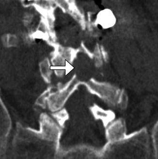
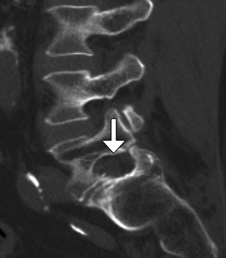
Fig. 11.1
Laminotomy. Coronal CT image demonstrates thinning and of the left L4 and L5 lamina (arrows) resulting in a widened interspinous space
Fig. 11.2
Foraminotomy. Sagittal CT image shows an artificially widening L5–S1 neural foramen (arrow)
11.2.2 Laminectomy
11.2.2.1 Discussion
Hemilaminectomy or unilateral laminectomy consists of resecting the lamina via dissection on one side of the interspinous ligament. This procedure is mainly performed in order to gain access for foraminotomy or discectomy. The hemilaminectomy defect is readily apparent on CT and MRI, but can be of variable width (Fig. 11.3).
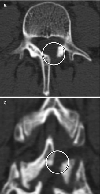
Fig. 11.3
Hemilaminectomy. Axial (a) and coronal (b) CT image demonstrates an opening in the left lamina (encircled)
In some instances, when preservation of the interspinous ligament is necessary, after the unilateral hemilaminectomy is performed, the ligamentum flavum is removed bilaterally for bilateral decompression of the neural structures.
Bilateral laminectomy consists of removing the spinous process along with both laminae, thereby “unroofing” the posterior spinal canal. This procedure is commonly performed for spinal canal decompression, particularly related to degenerative disc disease, spinal stenosis, epidural infections, epidural or subdural hematomas, and tumor. Bilateral laminectomy can be performed in conjunction with other procedures such as discectomy, facetectomy, and/or fusion for restoring stability. Both CT and MRI can readily show changes related to laminectomy and are routinely used to assess patients after surgery, even in the presence of hardware (Fig. 11.4). If the dura is opened (durotomy) or resected during the procedure, duraplasty is often performed, in which artificial dural replacement materials are used (Fig. 11.5). Too tight closure of the dura or duraplasty material can lead to compression of the spinal canal contents. This can be evaluated via MRI, in which there is concavity of the dura or duraplasty material (Fig. 11.6). Spinal cord contusions can occur secondary to decompression of severe stenosis. Contusions lead to typically transient and rarely permanent neurological deficits, with severity depending on location, which can be delineated on MRI as T2 hyperintense lesions (Fig. 11.7). Spinal cord infarct can result from disruption of the blood supply to the spinal cord and acutely appears as predominantly central high T2 signal with corresponding restricted diffusion on MRI (Fig. 11.8). This is due to hypoperfusion of the anterior spinal artery. Additional complications related to laminectomy are depicted in the “Failed Back Surgery” section.
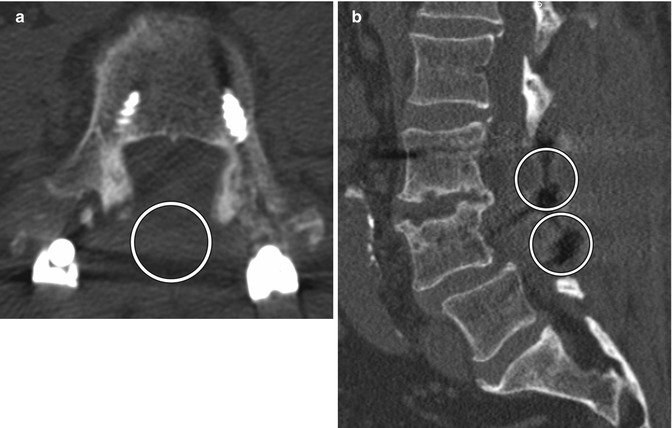
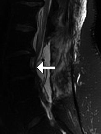

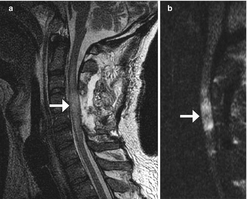
Fig. 11.4
Bilateral laminectomy. Axial (a) and sagittal (b) CT images show absence of the lamina and spinous processes at L3 and L4 (encircled). There is also posterior fusion hardware
Fig. 11.5
Laminectomy and duraplasty. Axial CT image (a) shows hyperattenuating Gore-Tex duraplasty material that lines the posterior spinal canal at laminectomy site (arrow). The sagittal T2-weighted MRI (b) shows that the duraplasty material has low signal (arrow), similar to normal dura
Fig. 11.6
Tight durotomy closure. The patient experienced worsening radiculopathy after surgery. Sagittal T2-weighted MRI shows compression of the cauda equina nerve roots by the dura (arrow) after recent laminectomy. The patient returned to the operating room for release of the durotomy repair and duroplasty with immediate relief of symptoms
Fig. 11.7
Spinal cord contusion. The patient woke up with a right hemiparesis. Axial T2-weighted MRI shows edema in the right lateral cortical spinal tract after cervical laminectomy and fusion for cervical spine stenosis
Fig. 11.8
Spinal cord infarct. The patient experienced paraplegia after surgery. Sagittal T2-weighted (a) and DWI (b) MR images show edema and restricted diffusion within the mid-cervical spinal cord at the same level of the laminectomies (arrows)
11.2.3 Facetectomy
11.2.3.1 Discussion
Facetectomy is mainly performed as part of treating far lateral disc herniations, facet hypertrophy, and limbus vertebral fractures. Facetectomy can essentially be performed as partial (usually medial) or total (Gil’s procedure). At times, a partial lateral facetectomy would be performed if an extra-foraminal decompression and approach is required. Various approaches can be used, including endoscopic, intertransverse, extra-foraminal, and transpars techniques. The degree of bony resection is best appreciated on CT, while MRI is optimal for the assessment of nerve root decompression (Figs. 11.9 and 11.10). Scar tissue often fills the facetectomy defect.
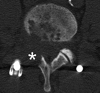
Fig. 11.9
Partial facetectomy. Preoperative axial CT image (a) shows bilateral facet degenerative changes. Postoperative axial CT image (b) shows resection of the medial aspects of the bilateral facet joints
Fig. 11.10
Total facetectomy. Axial CT shows complete absence of the right facet joint (*)
11.2.4 Microdiscectomy
11.2.4.1 Discussion
Microdiscectomy is a minimally invasive technique for treating symptomatic disc herniations and consists of curettage of disc material under surgical microscope visualization typically done with a midline or paramedian approach (Fig. 11.11). Portions of ligamentum flavum are often removed (flavectomy) in order to provide adequate access to the disc and to contribute to decompression of the spinal canal (Fig. 11.12). The posterior elements otherwise remain intact, thereby preserving stability of the spinal column. Clinical success of microdiscectomy is over 90% at 6 months and over 80% at 10 years. Complications are uncommon and include infection, dural tear, nerve root injury, and residual or re-herniation of disc fragments. Imaging is important for evaluating potential complications. Occasionally, hemostatic agents placed near the disc space can resemble a residual or re-herniated disc fragment, except these materials tend to have lower signal on T1-weighted and T2-weighted MRI sequences than does disc material (Fig. 11.13).
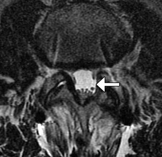
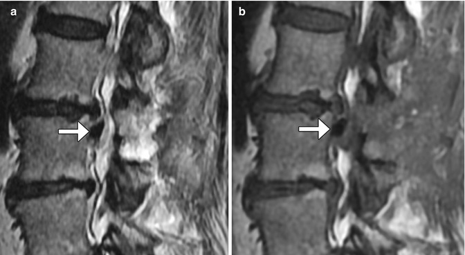
Fig. 11.11
Microdiscectomy. Preoperative sagittal T2-weighted MRI (a) shows a disc herniation at L5–S1 (arrow). Sagittal T2-weighted MRI (b) obtained after microdiscectomy shows interval resection of the herniated disc material, without significant alteration to the surrounding structures
Fig. 11.12
Flavectomy. Axial T2-weighted MRI shows absence of a portion of the left ligamentum flavum (arrow)
Fig. 11.13
Sagittal T2-weighted (a) and sagittal T1-weighted (b) MR images show low-intensity hemostatic material packed into the left lateral recess just inferior to the operated disc space (arrows)
11.2.5 Laminoplasty
11.2.5.1 Discussion
Laminoplasty is performed to widen the spinal canal while preserving as much of the anatomy as possible in order to conserve stability. Cervical laminoplasty is recommended for the treatment of cervical degenerative myelopathy or ossification of the posterior longitudinal ligament, with recovery rates of nearly 60% and improvement in about 80%. Commonly implemented surgical techniques consist of either performing bilaminar osteotomies and shifting the posterior elements backward or performing laminar osteotomy on one side and using a burr to thin the contralateral lamina in order to create a hinge and rotating the posterior elements posterolaterally and often trimming the spinous processes (Fig. 11.14). Alternatively, “French door” osteotomy can be performed in which a trough is drilled bilaterally in the lamina and the spinous process is split in half, opening up the spinal canal. The osteotomy gaps (“open door”) can be filled using bone or hardware (laminar prosthesis). Imaging may be performed after laminoplasty in order to evaluate for patients with complications such as persistent neck pain and diminished cervical motion, which can manifest as canal restenosis and loss of cervical lordotic alignment.
Fig. 11.14
Laminoplasty. Axial CT image (a) shows bilateral laminar osteotomies with posterior translation of the posterior elements, which are secured using a metal prosthesis on the right side. Axial CT image (b) in a different patient shows a right laminar hinge and bone graft (arrow) interposed in the left laminar open door, In addition, there has been resection of the spinous process
11.2.6 Vertebrectomy
11.2.6.1 Discussion
Vertebrectomy is sometimes necessary to treat extensive spine, tumors, infections, or fracture-dislocations. Part (partial vertebrectomy) or all (total vertebrectomy) of a vertebra can be removed. In particular, corpectomy is a specific type of partial vertebrectomy in which the vertebral body is partially or completely resected. Extensive vertebrectomy operations are often performed in stages. For example, en bloc bone resection can be performed using a diamond threadwire saw (T-saw), osteotome, and/or Gigli saw. The threadwire is sometimes left in the surgical bed for staged operations, such that the device may sometimes be encountered on interval imaging (Fig. 11.15). Subsequently, the vertebra can be reconstructed using iliac crest, tibia, and fibula strut grafts or various types of synthetic cages. Interbody cages, such as the Harms cage, are interposed vertically between vertebral bodies after vertebral body resection in order to promote fusion and provide mechanical support (Fig. 11.16). Expandable cage designs that can be adjusted to fit the length of the surgical defect are also available (Fig. 11.17). Morselized bone graft material is often packed inside the cage. The Harms cage is often used in combination with anterior or posterior fusion hardware, which yields fusion rates of over 90%. Carbon fiber cage systems can also be used for anterior column reconstruction following corpectomy, mainly in the setting of spine tumor and trauma surgery. Carbon fiber is a biocompatible material that can be used to make stackable cage systems. Except for the central metallic rod, on radiographs and CT, the carbon fiber components are radiolucent, while on MRI, the carbon fiber components are of low signal intensity on T1 and T2 sequences (Fig. 11.18). The role of imaging, particularly with CT, is to assess the progression of fusion and to evaluate for complications, such as graft or instrument displacement (Figs. 11.19 and 11.20). High-resolution CT with 3D renderings is particularly useful for assessing the position and integrity of the hardware.

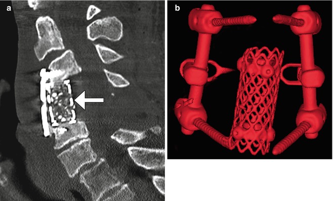

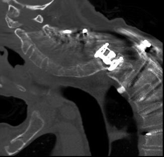
Fig. 11.15
Staged total vertebrectomy using threadwire saw and fibular bone graft reconstruction. Axial (a) and sagittal (b) CT images and the frontal radiograph (c) show the wire encircling a diseased vertebral body following laminectomy and posterior fusion. The follow-up sagittal CT image (d) shows interval corpectomy with fibular grafting and removal of the wire
Fig. 11.16
Harms cage. Sagittal (a) CT image shows a cage filled with bone graft (arrow). There is also anterior fusion hardware. 3D CT image (b) in a different case shows a cylindrical metal mesh cage and adjacent posterior fusion hardware
Fig. 11.17
Expandable cage. Sagittal CT image demonstrates the telescoping components of the metallic expandable cage (a). Photograph of an expandable cage (b)
Fig. 11.18
Corpectomy with stackable carbon fiber reconstruction. Frontal (a) radiograph shows corpectomy and fusion with stackable carbon fiber-reinforced cages constrained by a central metallic rod (arrow). The cages are otherwise radiolucent except for tiny metallic markers. Axial CT image (b) shows the low attenuation rectangular stackable cages and constraining metallic rod. Axial T2-weighted MRI (c) shows the low signal intensity rectangular carbon fiber cage
Fig. 11.19
Slippage of expandable cage. Sagittal CT image shows complete dislocation of the spine from the corpectomy cage with associated angular kyphosis of the cervical spine and compromise of the spinal canal contents
Fig. 11.20
Dislocated bone grafts. Frontal radiograph (a) and coronal CT image (b) show lateral displacement of the bilateral fibular grafts out of the corpectomy defect such that the inferior end of the right graft and the superior end of the left graft no longer contact the adjacent endplates
11.2.7 Cordectomy
11.2.7.1 Discussion
Cordectomy involves resection of the spinal cord. This unusual procedure is reserved for selected patients with severe neurologic deficits and symptoms related to intramedullary tumors or extramedullary tumors that invade the spinal cord. Laminectomy, corpectomy, or vertebrectomy can be performed in conjunction with cordectomy. Therefore, materials used to stabilize the spine, such as methyl methacrylate, can safely extend into the spinal canal at the level of the cordectomy (Fig. 11.21).
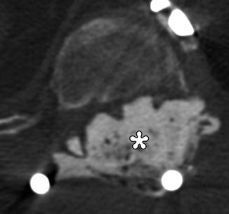
Fig. 11.21
Cordectomy. The patient is status post chordoma excision with recurrence, which required resection of the spinal cord and placement of posterior rods and methyl methacrylate for spinal stabilization. Axial CT image shows cement filling the spinal canal (*)
11.3 Spine Stabilization and Fusion
11.3.1 Halo and Traction Devices
11.3.1.1 Discussion
A variety of surgically affixed devices are available for immobilization and traction of unstable cervical spine fractures and dislocations, including halo vests and Gardner-Wells tongs (Figs. 11.22 and 11.23). Halo vests comprise a metallic ring secured to the skull via screws. The ring is attached to a padded fiberglass or plastic thoracic cast by metal struts. The Gardner-Wells device consists of two screws attached to both sides of the skull that support the tongs to which traction is applied. Both types of devices provide excellent long-term cervical spine fixation. Pullout of the screws is a rare, but potentially devastating complication. In addition to pullout, screw site infection or screw breaking through the inner cortex of the skull is a rare complication. In general, devices composed of aluminum or graphite-carbon composites and plastic joints are MRI compatible.

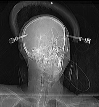
Fig. 11.22
Halo vest. Scout image shows the device secured to the skull and shoulder girdle
Fig. 11.23
Gardner-Wells device. Scout image shows the traction device with bilateral scalp screw fixation
11.3.2 Bone Graft Materials
11.3.2.1 Discussion
Several options are available for promoting bone fusion, including autologous, allograft, and synthetic bone grafts. Autologous bone grafts are often harvested from the iliac crest, rib, or local lamina, and spinous process (Fig. 11.24). Alternatively, a trephine system can be used to obtain a core of cancellous bone from an adjacent vertebral body, which leaves a cylindrical defect in the anterior portion of the vertebral body and pedicle (Fig. 11.25). Allografts are derived from cadavers and are available as bone chips or cylinders from fibula or rib and retain some bony structure (Fig. 11.26). Ultimately, an uninterrupted bony bridge should form across the vertebral bodies and facet joints as the bone graft fusion matures (Fig. 11.27).

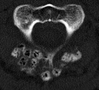
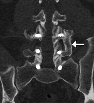
Fig. 11.24
Autologous bone graft harvested from the iliac crest. Axial CT of the spine (a) shows bilateral cortical and cancellous bone fragments with sharp edges (encircled). Demineralized bone matrix was also applied. Axial CT at a lower level (b) shows the iliac donor site packed with hemostatic agent (arrow)
Fig. 11.25
Local vertebral body bone harvest. Axial CT image shows cylindrical defect in the anterior vertebral body (arrow)
Fig. 11.26
Allograft bone chips. Axial CT image shows numerous cubes of cancellous cadaveric bone grafts within an adjacent to the laminectomy site. Many of the chips show a trabecular bone structure and contain air
Fig. 11.27
Mature bone graft fusion. Coronal CT image shows a solid fusion mass that bridges the left L4 and L5 vertebrae from transverse process to transverse process (arrow)
The main types of synthetic bone graft substitutes that are used during spine surgery include ceramics, demineralized bone matrix, and composite materials. Demineralized bone matrix consists of non-collagenous proteins, bone growth factors, and collagen, which are intended to stimulate bone healing. These materials are radiolucent and difficult to visualize directly on imaging. Demineralized bone matrix is available in powder form or as putty that can be used to fill voids (Fig. 11.28). Sometimes demineralized bone matrix is combined with bone grafts, which has attenuation intermediate between medullary and cortical bone. Ceramics include calcium sulfate, hydroxyapatite, tricalcium phosphate, or a combination of hydroxyapatite and tricalcium phosphate that are available in the form of pellets, pastes, or cement. These materials are denser than native bone. Composite materials such as moldable morsels contain mixtures of ceramic and collagen or other demineralized bone matrix components. The mineralized component (i.e., calcium phosphate) provides compressive strength and a substrate for bone formation, while the collagen contributes tensile strength and promotes hemostasis at the surgical site. On CT, such materials appear as grainy foci of heterogeneous attenuation (Fig. 11.29).
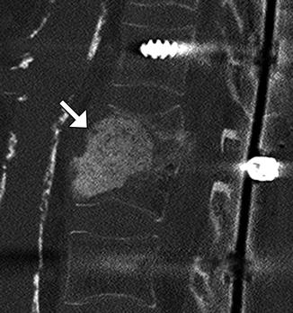
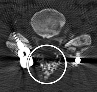
Fig. 11.28
Demineralized bone matrix. Sagittal CT image shows amorphous hyperattenuating material filling the space of partially collapsed vertebral bodies secondary to prior osteomyelitis (arrow)
Fig. 11.29
Composite Mozaik moldable morsels. Axial CT image shows the mixture of bone putty and moldable morsels as numerous tiny heterogeneously hyperattenuating foci (encircled) spanning the posterior surgical defect adjacent to the segmental instrumentation
Recombinant bone morphogenic protein (BMP) is often added to bone graft agents in order to promote fusion. This substance promotes bone resorption or osteolysis. Despite this finding, fusion typically progresses and matures within 2 years. In fact, BMP expedites arthrodesis. On imaging, BMP-induced osteolysis appears as multiple cystic spaces in the endplate adjacent to the implant (Fig. 11.30). BMP is also known to form an excessive inflammatory response with excessive fluid collections in the early postoperative period, sometimes even leading to undesired bone formation within the spinal canal.
Fig. 11.30
Recombinant BMP-induced osteolysis. Sagittal (a) CT image shows rounded lucencies (arrow) along the inferior endplate of the vertebral body above the interbody fusion. Sagittal T2-weighted MRI (b) shows high-intensity foci (arrows) within the endplates adjacent to the interbody fusion material
11.3.3 Implantable Bone Stimulators
11.3.3.1 Discussion
Implantable (internal) bone stimulators are devices that deliver electrical currents to promote bone growth and healing and to expedite fusion. This device consists of electrodes that are positioned in contact with the site of spinal fusion and a small power source that is implanted in the subcutaneous tissues (Fig. 11.31). The role of imaging is to confirm proper positioning of the electrodes and assess progression of bony fusion or healing.
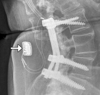
Fig. 11.31
Bone stimulator. Lateral radiograph shows the leads in contact with the fusion masses and the battery pack (arrow) implanted in the subcutaneous tissues
11.3.4 Odontoid Screw Fixation
11.3.4.1 Discussion
Anterior fixation of odontoid fractures consists of securing the fracture fragment with one or two lag or cortical screws depending on the diameter of the dens. A lag screw is used in order to help reduce the fracture. Complications of this procedure include hematomas, dysphagia, hoarseness, and vascular, spinal cord, or nerve root injuries. Radiographs and/or CT may be obtained for follow-up, especially in order to assess for union (Fig. 11.32). The tip of the screw can often safely project beyond the posterosuperior edge of the dens by several millimeters. Other options for treating odontoid fractures include posterior spinal fusion or halo-vest immobilization.
Fig. 11.32
Odontoid screw fixation. Sagittal CT (a) shows anterior fixation of the dens fracture via a single lag screw. The dens fracture fragments are well aligned, but remain unfused. Photograph of an odontoid lag screw (b)
11.3.5 Occipitocervical Fusion
11.3.5.1 Discussion
Indications for occipitocervical fusion include anterior and posterior bifid C1 arches with instability, absent occipital condyles, severe reducible basilar invagination, unstable dystopic os odontoideum, unilateral atlas assimilation, traumatic occipitocervical dislocation, complex craniovertebral junction fractures of C1 and C2, transoral craniovertebral junction decompression, cranial settling in Down’s syndrome, tumors, and inflammatory disease such as Grisel’s syndrome.
A variety of internal fixation methods have been developed for posterior craniocervical junction fusion including sublaminar wiring (Fig. 11.33) and occipital rods and plates (Fig. 11.34). Bone grafts are often added alongside the posterior elements in order to promote bony fusion. Interestingly, the degree of stability does not seem to correlate with the presence or absence of radiographically evident bone graft fusion. Sublaminar wires have the potential to unravel, resulting in recurrent malalignment and instability (Fig. 11.35) and generally provide less stability than screw constructs. In addition, wire fracture can lacerate the spinal cord. The occipital screws can sometimes penetrate the inner table of the occipital bone (Fig. 11.36), which may not necessarily result in cerebellar injury, especially if it is only by a small extent. Transarticular screw fixation of the cervical spine can encroach upon the transverse foramina and potentially injure the vertebral arteries or even impinge upon the internal carotid arteries (Fig. 11.37). The incidence of nonunion or loosening is about 7% for occipitocervical fusion and atlantoaxial fusion, which appears as lucency around the hardware on CT (Fig. 11.38).
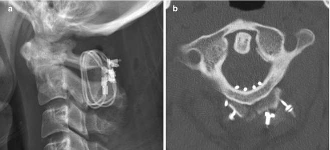
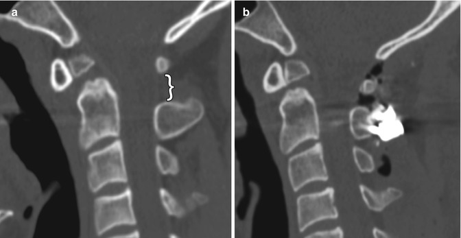
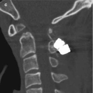
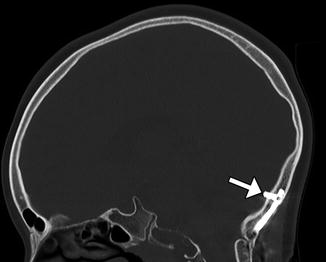
Fig. 11.33
Atlantoaxial fusion with sublaminar wiring. The patient has a history of an unstable dens fracture. Lateral radiograph (a) and axial CT image (b) demonstrate posterior atlantoaxial fixation with bilateral cables that pass into the spinal canal and around iliac crest bone grafts applied posterior to the C1 and C2 arches
Fig. 11.34
Occipitocervical fusion with rods and screws. Sagittal CT image (a) shows the curvilinear posterior rod (arrow) attached to the occipital bone via plate (arrow) and screws and to the upper cervical spine via lateral mass screws. Photograph of an occipital plate (b)
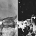
Fig. 11.35
Unraveled sublaminar wire. The patient has a history of unstable os odontoideum. Preoperative sagittal (a) CT image shows a dystopic os odontoideum angled anteriorly and a widened C1–C2 interspinous space (bracket). Initial postoperative sagittal CT image (b) shows interval fixation of the posterior elements of C1 and C2 with sublaminar wires and application of bone graft. There is resulting decreased C1–C2 interspinous distance and angulation of the os odontoideum. Subsequent sagittal CT image (c) shows interval widening of the C1–C2 interspinous distance and angulation of the os odontoideum similar to the configuration before surgery
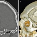
Fig. 11.36
Occipital screw intracranial penetration. Sagittal CT image shows penetration of the inner table with intracranial extension of a lateral occipital plate screw (arrow)
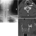
Fig. 11.37
Vascular compromise by screw malposition. Axial CT image (a) shows a right lateral mass screw within the right foramen transversarium (arrow). Coronal CTA image in another patient (b) shows impingement of the left internal carotid artery (encircled)
Fig. 11.38
Hardware loosening. Sagittal CT image (a) shows lucency surrounded the hardware in the occipital bone (arrow). Sagittal CT image (b) shows lucencies surrounding multiple lateral mass screws (arrows), which have begun to pull out
11.3.6 Anterior Cervical Fusion
11.3.6.1 Discussion
Anterior cervical plates are commonly used for fusion to treat degenerative conditions, as well as fractures, infections, and tumors. The hardware most commonly spans two or three vertebral body levels, but can be as many as five vertebral bodies. The plates are affixed to the vertebral bodies via screws (Fig. 11.39). The screws should not transgress the adjacent disc space. The plates and screws are most often metallic, although some biodegradable devices have been developed. Another technique for anterior cervical fusion is the use of interbody devices without the use of plate (stand-alone). These devices are typically composed of polyether ether ketone (PEEK) and are fixed to the vertebral body either with two or three screws or fins (Fig. 11.40). For example, Zero P is a Synthes device used as a stand-alone implant in cervical interbody fusion and incorporates both the interbody cage and fixation plate. The device has a low profile anteriorly, resulting in decreased soft tissue and esophageal irritation. Zero P and all similar devices are designed to reduce adjacent level ossification, since the plate does not irritate the adjacent disc.
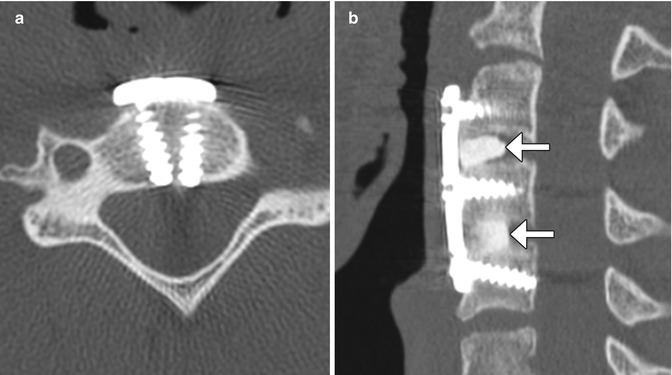

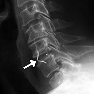
Fig. 11.39
Anterior cervical discectomy and fusion (ACDF). Axial (a), sagittal (b), and 3D (c) CT images show an anterior cervical plate secured flush against the vertebral bodies via screws. Anterior discectomy and placement of intervertebral allografts was also performed (arrows)
Fig. 11.40
Stand-alone anterior cervical discectomy and fusion. Lateral radiograph shows the LDR ROI-C cage and fins C6-7 (arrow)
Complications of anterior cervical fusion include hardware infection, dysphagia, hematoma, esophageal perforation, subsidence, spinal cord injury in the cervical spine, and bowel, or vascular injury in the lumbar spine. A fluid collection and foci of gas can be identified in the prevertebral space on CT with hardware infection (Fig. 11.41). MRI is used to evaluate for an associated epidural abscess.
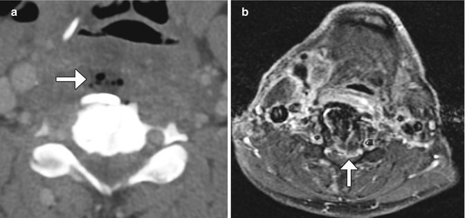
Fig. 11.41
Infection. Axial CT image (a) demonstrates a fluid collection containing foci of gas anterior to the anterior cervical spine hardware (arrow). Axial fat-suppressed post-contrast T1-weighted MRI (b) shows extensive enhancement in the prevertebral space as well as extension into the anterior epidural space (arrow)
Subsidence of the hardware or graft material is a chronic process in which the materials penetrate into the adjacent vertebral bodies or disc spaces. This can lead to postoperative deformity and sclerosis, which can be assessed on CT (Fig. 11.42).

Fig. 11.42
Bone graft subsidence and retropulsion. Sagittal CT image shows the bone graft dowel (arrow) protruding into the spinal canal and adjacent vertebral bodies
Cervical spinal cord injury can rarely occur during screw placement, potentially creating a transecting spinal cord injury (Fig. 11.43). Dysphagia and dysphonia are common following anterior cervical fusion due to injury to the pharyngeal plexus and recurrent laryngeal nerve. CT can be used to assess the neck soft tissue in such cases, which may reveal supraglottic edema (Fig. 11.44). Otolaryngology consultation should be obtained for patients with postoperative dysphagia or dysphonia, particularly if that persists longer than 1–2 months.
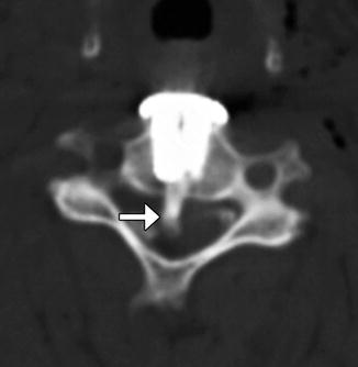
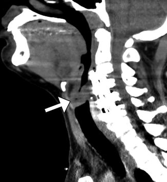
Fig. 11.43
Iatrogenic spinal cord transection from anterior cervical fusion. Axial CT image of the cervical spine shows a cylindrical bone fragment (arrow) within the central spinal canal. There is anterior fusion hardware and soft tissue air from the recent surgery (Courtesy of Richard White, MD)
Fig. 11.44
Supraglottic swelling after anterior cervical fusion. The patient experiences difficulty breathing after cervical spine surgery. Sagittal CT image shows multiple level cervical anterior fusion with surgical hardware and swelling of the supraglottic soft tissues (arrow)
11.3.7 Anterior Approach Thoracolumbar Spine Stabilization Devices
11.3.7.1 Discussion
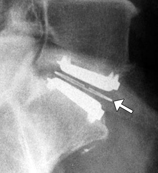
Anterior surgical approach short-segment stabilization systems, such as the Kaneda device (DePuy Spine, Raynham, Mass) and the Vantage plate (Medtronic, Sofamor Danek, Memphis TN), are adjustable devices that can provide rigid fixation of the thoracolumbar vertebral column in the setting of burst fracture stabilization or corpectomy via anterior approaches. The Kaneda device consists of a rod and screws with additional staples, which reinforce the purchase of the screws in the vertebrae, resulting in robust fixation (Fig. 11.45). The Vantage plate features several slots for selecting the optimal level of the screws that are secured to adjacent vertebral bodies (Fig. 11.46). The device is inserted by using an anterior approach.
Fig. 11.45
Kaneda device. Axial (a) and coronal (b) CT images show the rod and screw system positioned along the left lateral aspect of the vertebrae. An expandable cage is also present in the intervening space
Fig. 11.46
Adjustable plate system. Lateral thoracic spine radiograph (a) and coronal CT image (b) show the adjustable plate (arrow) spanning the corpectomy site, where there is a tibial structural allograft
11.3.8 Posterior Fusion
11.3.8.1 Discussion
Most thoracic and lumbar spine fixation is performed via a posterior approach, most commonly using rods and pedicle screws. Pedicle screws attach posteriorly to rods or plates via clamps or bolts and have shallow cancellous threads that pass through the pedicle and into the vertebral body. The screw should enter 50–80% of the vertebral body and be parallel to the endplates with at least 2 mm of separation. The screws can produce considerable beam-hardening artifacts on CT, which can be minimized through the use of metal artifact reduction software (Fig. 11.47). On MRI, the pedicle screws can produce variable degrees of metal susceptibility artifact that can obscure adjacent structures, which is more pronounced at higher magnetic field strength (Fig. 11.48). Imaging via CT is sometimes performed in order to assess whether the screws are malpositioned (Fig. 11.49). Medial malpositioning is a potentially devastating complication that can result in spinal cord or nerve injury. Laterally malpositioned screws can injure exiting nerve roots. Pedicle screws can also potentially cause vascular injury, such as the aorta or inferior vena cava, if they are too long and exit the anterior vertebral body. Although transdiscal screws are sometimes used for fixation in scoliosis surgery, penetration into the disc space is generally avoided. Another option for securing rods is through lateral mass screws, which are situated between the superior and inferior articular processes, thereby lowering the likelihood of the types of malpositioning associated with pedicle screws (Fig. 11.50).
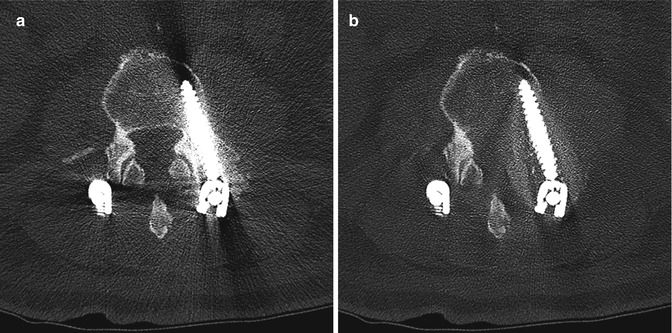
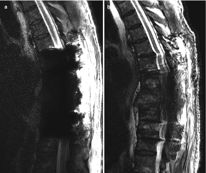
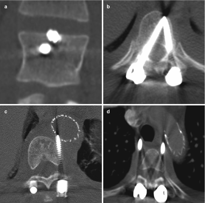
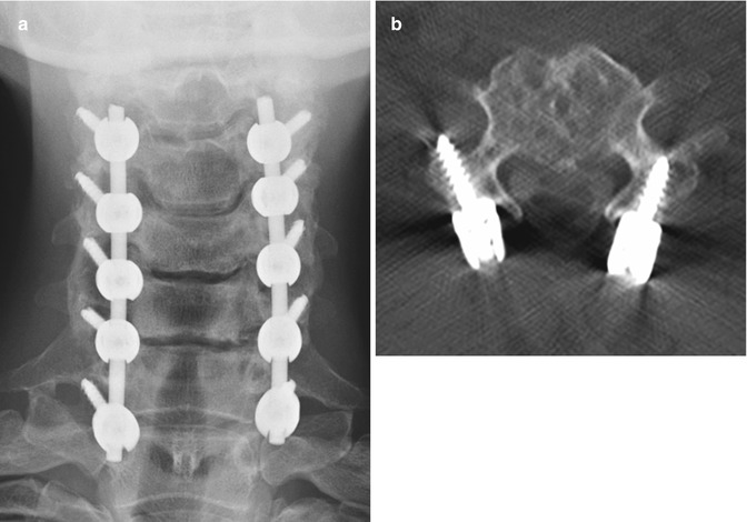
Fig. 11.47
Metal artifact reduction software. Axial CT image (a) shows extensive metal artifact associated with the surgical hardware. The corresponding axial CT image with metal artifact reduction software (b) shows much less artifact
Fig. 11.48
Spine hardware artifacts at 3 T versus 1.5 T. Sagittal T2-weighted MRI performed on a 3 T scanner (a) shows extensive susceptibility artifact related to the pedicle screws, which obscures the surrounding anatomy. Sagittal T2-weighted MRI performed on a 1.5 T scanner (b) shows much less artifact from the hardware
Fig. 11.49
Malpositioned screws. Coronal CT image (a) shows a screw that breaches the superior endplate and enters the intervertebral disc space. Axial CT image (b) in another patient shows medial malposition of the right thoracic pedicle screw into the spinal canal (arrow), resulting in paraplegia. Axial CT images (c and d) in another patient show screws impinging upon the aorta, which contains an endograft and impinging upon the trachea
Fig. 11.50
Lateral mass screws and rods. Frontal radiograph (a) and axial CT image (b) show bilateral screws traversing the lateral mass. Unlike transpedicular screws, lateral mass screws are directed laterally
Instead of screws, rods can also be secured to the vertebrae via sublaminar wires or cables (Fig. 11.51). Sublaminar wires or cables pass around the lamina and rods and are twisted or clamped at their ends. Alternatively, laminar or sublaminar hooks can be used for compression or distraction. Hooks that pass below the lamina are termed up-going, while those that pass above the lamina are termed down-going (Fig. 11.52). These two configurations are usually applied simultaneously for optimal stability. The hooks are connected to the rods via screws, bolts, or washers. Facet screw fixation is an alternative to pedicle screw fixation whereby the articular facets are fused. The screws are not attached to rods but may be used in conjunction with interbody fusion or anterior plating (Fig. 11.53).

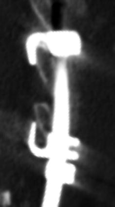
Fig. 11.51
Wire fixation. 3D CT image shows sublaminar wires attached to the rods
Fig. 11.52
Pedicle hooks. Sagittal CT image shows upgoing and down-going hooks secured to the laminae and attached to a rod
Fig. 11.53
Facet screws. Frontal radiograph (a) and axial CT image (b) demonstrate bilateral L5–S1 facet screws. Anterior fusion was also performed
11.3.9 Scoliosis Rods
11.3.9.1 Discussion
A variety of rods are used for posterior spinal fixation in the treatment of scoliosis, including Harrington, Knodt, and Luque (Figs. 11.54, 11.55, and 11.56). In contrast to threaded Knodt rods, Harrington rods feature flanged ends, which can attach to laminar hooks. Harrington rods are usually paired and interconnected by segmental wires for added stability. Luque rods are spinopelvic fixation devices that can be used to treat scoliosis, among other applications. The apparatus has a characteristic L shape in which the inferior angled portion can be affixed to the ilium. Depending on the direction in which the hooks are placed, the rods can provide either compression or distraction. Perhaps the most common usage of these rods is for treatment of severe scoliosis, which can sometimes be partially corrected.
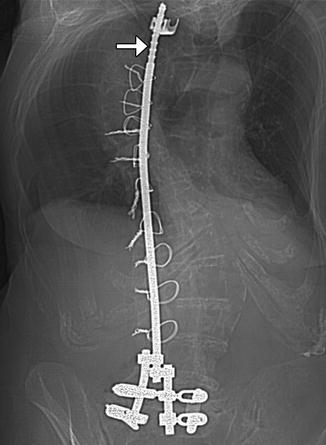
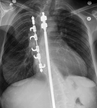
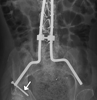
Fig. 11.54
Harrington rod. Frontal radiograph shows a metallic rod with flanged end (arrow) spanning the thoracolumbar spine in a patient with scoliosis
Fig. 11.55
Knodt rods. Frontal radiograph shows two rods with threaded ends
Fig. 11.56
Luque rods. Frontal radiograph shows instrumentation with pelvic fixation using the Galveston technique (arrow)
Complications include rod fracture or dislocation and screw pullout, which can be predisposed by the high torque inherent to the length of the hardware (Figs. 11.57, 11.58, and 11.59). The thoracolumbar fixation hardware may also lead to “flat-back” syndrome, in which there is loss of lumbar lordosis (Fig. 11.60). Scout and 3D CT reconstructions are particularly helpful for evaluating mechanical complications, while MRI might be more useful for assessing spinal canal involvement.
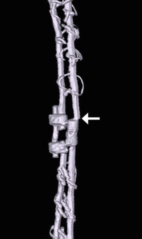
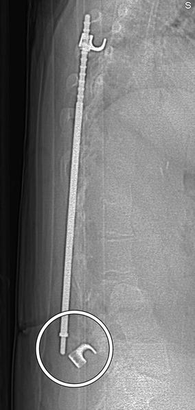
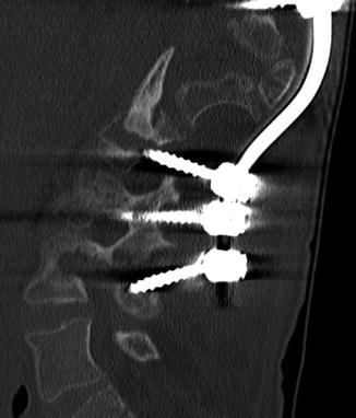

Fig. 11.57
Rod fracture. 3D CT image shows a displaced fracture of one of the Harrington rods (arrow)
Fig. 11.58
Rod dislocation. Lateral scout images show posterior displacement of the inferior end of the Harrington rod (encircled) with separation from the hook
Fig. 11.59
Screw pullout. Sagittal CT image shows multiple screws that are posteriorly displaced along with the inferior end of the scoliosis rod
Fig. 11.60
Flat-back syndrome. The patient presents with chronic low back pain and poor posture. Sagittal CT image demonstrates straightening vertebral alignment with loss of lumbar lordosis along the same levels as the rods
11.3.10 Vertebral Stapling
11.3.10.1 Discussion
Vertebral body stapling is a minimally invasive, fusionless alternative to reduce curvature progression in patients with mild idiopathic scoliosis. Vertebral staples are composed of shape memory alloys that can be custom fit to the size of the vertebral body. The staples are inserted into the lateral aspects of the vertebral bodies across the disc spaces unilateral to the convex side of the scoliosis (Fig. 11.61). A thoracoscopic approach can be used for thoracic curves and a mini-open retroperitoneal approach for lumbar curves. Initial success rates are high and with few associated complications, although long-term follow-up is not yet available.
Fig. 11.61
Vertebral staples. Frontal (a) and lateral (b) radiographs show the C-shaped staples positioned in multiple contiguous vertebral bodies along the convex side of the thoracic scoliosis
11.3.11 Vertical Expandable Prosthetic Titanium Rib (VEPTR)
11.3.11.1 Discussion
VEPTR is used to gradually correct chest wall deformity and scoliosis in selected pediatric patients, with repeated lengthening sessions. The devices are typically implanted at the time of wedge thoracostomy and consist of an adjustable metal rod that is interposed vertically between ribs on the concave side of the scoliosis for distraction (Fig. 11.62). Most patients with VEPTR maintain near-normal thoracic spine growth rates and satisfactory lung volumes. Complications include device migration, infection, and brachial plexus injury.
Fig. 11.62
Vertical expandable prosthetic titanium rib. The patient is a child with a history of severe scoliosis and associated chest wall deformity. Frontal (a) and lateral (b) radiographs show two metallic devices interposed between the right ribs
11.3.12 Interbody Fusion
11.3.12.1 Discussion
The goal of lumbar interbody fusion with prosthetic devices is to provide stability while promoting bony ingrowth. Many materials and devices have been used for this purpose, including bone threaded bone graft dowels or femoral rings, metal cages, and polymer cages. Femoral ring grafts are cylindrically shaped and inserted into the intervertebral disc space via anterior lumbar interbody fusion, posterior lumbar interbody fusion, or transforaminal lumbar interbody fusion approach (Fig. 11.63). A major disadvantage of such allograft device is the risk of disease transmission. Wide varieties of metal cages have been and continue to be developed. The first-generation Bagby and Kulich (BAK) and second-generation Ray threaded fusion cages are cylindrical, hollow, porous, threaded, titanium alloy cages that can be screwed into position in the intervertebral disc space (Fig. 11.64). The more recent third-generation LT-CAGE has been widely used in North America and has a trapezoidal, tapered configuration that provides increased surface area for bone growth and facilitates restoration of lumbar lordosis (Fig. 11.65).
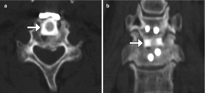
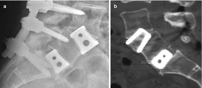
Fig. 11.63
Femoral ring allograft. Axial (a) and coronal (b) CT images show a cylindrical bone fragment inserted into the intervertebral disc space (arrows)
Fig. 11.64
Threaded cage. Sagittal (a) and coronal (b) CT images show two cylindrical hollow cages screwed into the intervertebral disc space
Fig. 11.65
Tapered LT-CAGE. Lateral radiograph (a) and sagittal CT image (b) show two metallic cages fitted into the intervertebral disc spaces. Mature bony fusion is most apparent on the CT
More recent interbody fusion devices are mainly composed of polyether ether ketone (PEEK) or biocompatible high-density carbon fiber. These materials are radiolucent, which facilitates visualization of the bone graft-vertebral body endplate interface. The devices also contain press-fit titanium markers in order to demarcate the boundaries of the device on radiographs. Many designs are in use, but generally are rectangular with grooves in order to promote vertebral body attachment. There are a variety of approaches that can be used for interbody fusion (Figs. 11.66, 11.67, 11.68, 11.69, 11.70, and 11.71 and Table 11.2).
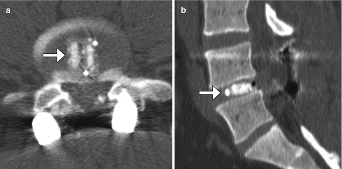
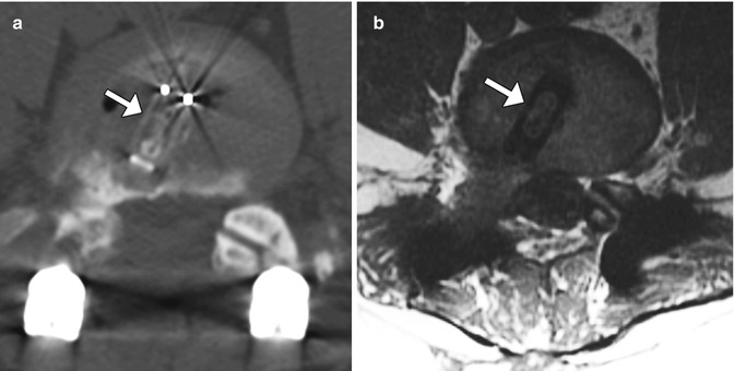
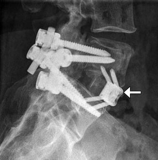
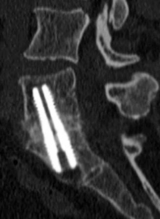
Fig. 11.66
PLIF. Axial (a) and sagittal CT (b) images show the radiolucent PEEK cage with metallic markers and filled with bone graft (arrows) in the midline of the intervertebral disc space. Laminectomy and posterior fusion hardware is also present
Fig. 11.67
TLIF. Axial CT (a) and axial T1-weighted (b) show the PEEK cage (arrows) positioned obliquely in the intervertebral space at nearly a 45° angle with respect to the sagittal plane
Fig. 11.68
XLIF. Axial (a) and coronal (b) CT images show the metallic markers of the XLIF device, which is positioned in the intervertebral space. There is bone graft material within the device. Axial T1-weighted (c) MRI shows the XLIF device as low signal intensity with a “figure of 8” shape
Fig. 11.69
ALIF. Lateral radiograph shows a Synfix device implanted in the L5–S1 anterior disc space (arrow). Posterior stabilization hardware is also present
Fig. 11.70
Stalif. Frontal radiograph (a) and sagittal CT image (b) show that the device composed of both radiolucent and metallic parts, including titanium screws that enter the anterior vertebrae above and below. Note the absence of additional hardware. As such, the device “stands alone”
Fig. 11.71
Transsacral fusion. Sagittal CT image shows the vertically oriented axial lumbar interbody fusion hardware and mature bony bridging across the L5–S1 disc space
Table 11.2
Types of interbody fusion
Device | Description | Photographs of various types of interbody fusion devices |
|---|---|---|
PLIF (posterior lumbar interbody fusion) | Consists of a posterior midline approach to the disc space. The interbody cage is inserted into the intervertebral disc space via a laminectomy or hemilaminectomy defect. As a result, the long axis of the device is typically positioned nearly parallel to the sagittal plane. Concurrent facetectomy is often performed |  |
TLIF (transforaminal lumbar interbody fusion) | Modification of the PLIF procedure, in which the interbody fusion prosthesis is more lateral. The long axis of the cage tends to be positioned obliquely (approximately 45°) with respect to the sagittal plane. This procedure can be performed via a midline approach as a PLIF or a minimally invasive approach with two paramedian incisions. Full facetectomy (unilateral or bilateral) is also performed. Fixed-size or expandable cages can be inserted into the disc space | |
XLIF (extreme lateral interbody fusion; NuVasive, Inc., San Diego, CA) | Proprietary PEEK implant that is inserted laterally into the intervertebral space through a minimally invasive retroperitoneal approach. These implants have a characteristic of long, rectangular shape, designed to maximize surface area on which the epiphyseal ring can rest. There are also slots for packing bone graft. Other vendors endorse this approach and have different variations on the lateral cage | |
OLIF (oblique lumbar interbody fusion; Medtronic, Minneapolis, MN) | A variant on the XLIF where the lateral spine is approached obliquely instead of orthogonally. The cages are placed in a similar fashion to the XLIF technique | |
ALIF (anterior lumbar interbody fusion) | Consists of anterior discectomy and insertion of the interbody prosthesis via a retroperitoneal approach. The procedure can be performed with or without posterior stabilization. However, the addition of pedicle screw fixation with ALIF results in a significant increase in the rate of interbody fusion | |
Stalif (stand-alone lumbar interbody fusion) | Can absorb energy, handle the normal weight of the body, and minimize stress on adjacent levels. Thus, the devices do not require additional fusion procedures, such as posterior pedicle screw and rod fixation | |
AxiaLif (transsacral fusion) | Can be performed using the AxiaLif® system (TranS1, Inc., Wilmington, NC). Initially, a series of guide pins and dilator tubes are inserted under fluoroscopic guidance and used to obtain access to the L5–S1 disc space. Subsequently, a discectomy is performed percutaneously. Finally, a threaded titanium pin is placed across the disc space. This procedure is often combined with posterior fixation with facet or pedicle screws introduced through a minimally invasive technique | Photograph of AxiaLif device. (Courtesy of Quandary Medical) LLC  |
Imaging can be used to assess the position of the implants, which should be located at least 2 mm anterior to the posterior wall of the vertebral body. Another role of imaging following interbody fusion surgery is to assess fusion versus pseudarthrosis. Radiographs with lateral flexion and extension views can be used for this purpose, although the accuracy is highly dependent upon precise positioning and the type of implant. Rather, CT is the modality of choice for evaluating interbody fusion, although the streak artifact from the early stainless devices can obscure adjacent bone formation. Early bone healing can often be appreciated at 3 months and is usually nearly complete at 6 months after surgery.
11.4 Dynamic Stabilization Devices of the Spine
11.4.1 Total Disc Replacement
11.4.1.1 Discussion
Total disc replacement is an option for treating degenerative disc disease, in which motion at the operated level is preserved. In theory, this technique results in less load transfer to adjacent levels compared with fusion. Several types of disc replacement are available, including one-piece implants and implants with single- or double-gliding articulations with metal-on-metal or metal-on-polymer bearing surfaces (Figs. 11.72, 11.73, and 11.74). For example, the Charite® device is a three-part device consisting of two cobalt-chromium-molybdenum (CoCrMo) alloy endplates and a radiolucent ultra-high-molecular-weight polyethylene core. The radiolucent core is delineated by a small radiopaque metal wire. There are small “teeth” along the device endplates in an attempt to anchor the device in the vertebral endplates and limit migration. The endplates are coated with porous plasma-sprayed titanium and with calcium phosphate to promote bony ingrowth. ProDisc is also a three-part disc arthroplasty device with two metallic endplates and a radiolucent inlay that snaps onto the lower endplate to prevent extrusion. The device is secured in the adjacent vertebral bodies by ridged keels along both of the endplates (Fig. 11.75).
 Imaging of the Postoperative Skull Base and Cerebellopontine Angle
 Imaging of Cerebrospinal Fluid Shunts, Drains, and Diversion Techniques
 Imaging the Paranasal Sinuses and Nasal Cavity
 Imaging the Postoperative Scalp and Cranium
 Imaging of Vascular and Endovascular Surgery
 Imaging the Postoperative Neck


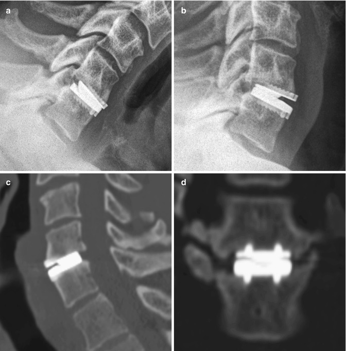
Fig. 11.72
Prestige cervical spine total disc prosthesis. Flexion (a) and extension (b) views of the cervical spine show the range of motion of the device. Sagittal (c) and coronal (d) CT images show the device positioned within the disc space, secured by two rows of corrugated keels
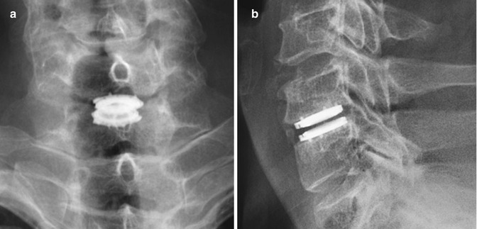
Fig. 11.73
Advent cervical spine total disc prosthesis. Frontal (a) and lateral (b) radiographs show the total disc replacement prosthesis in the lower cervical spine
Related posts:
Imaging of the Postoperative Skull Base and Cerebellopontine Angle
Imaging of Cerebrospinal Fluid Shunts, Drains, and Diversion Techniques
Imaging the Paranasal Sinuses and Nasal Cavity
Imaging the Postoperative Scalp and Cranium
Imaging of Vascular and Endovascular Surgery
Imaging the Postoperative Neck
Stay updated, free articles. Join our Telegram channel
Full access? Get Clinical Tree
