Fig. 4.1
Occipital nerve stimulator. The patient has a history of intractable migraine headaches. Frontal (a) and lateral (b) radiographs of the skull show the electrodes situated in the bilateral occipital subcutaneous tissues (arrows)
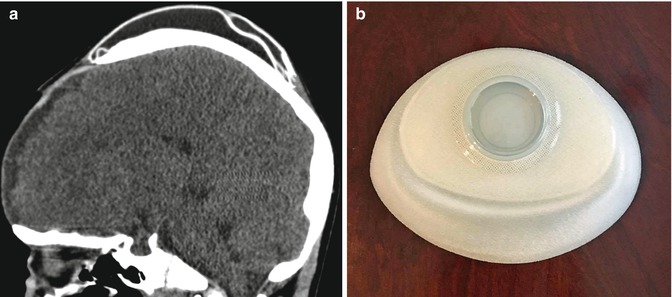
Fig. 4.2
Scalp tissue expander. The patient has a history of severe burns to the face. Sagittal CT image (a) shows a saline-filled skin expander device within the scalp, posterior to the craniectomy defect. Photograph of an unfilled expander (b) (Courtesy of Melissa Guilbeau)
4.3 Temporal Fossa Implants
4.3.1 Discussion
Soft tissue deficiency in the temporal fossa can produce cosmetic impairment and can result from the transposition of temporalis myofascial flaps and tumor debulking procedures, among other surgeries. The contours of the temporal fossa can be augmented using implants, such as prefabricated porous high-density polyethylene (Fig. 4.3), silicone (Fig. 4.4), and methyl methacrylate (Fig. 4.5). The implants are usually inserted via a hemicoronal approach and can be secured using titanium screws to the underlying bone.
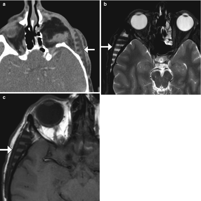
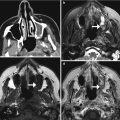
Fig. 4.3
Porous polyethylene temporal fossa implant. Axial CT image (a) shows a low-attenuation polyethylene implant with inner ridged surface positioned in the left temporal fossa (arrows). There is also left orbital exenteration. Axial T2-weighted (b) and axial T1-weighted (c) MR images in a different patient show a polyethylene implant in the right temporal fossa (arrows) with near-anatomic contours of the overlying scalp
Fig. 4.4
Silicone temporal fossa implant. The patient has a history of neurofibromatosis and is status post tumor debulking. Axial T2-weighted MRI shows a low-intensity plate in the right temporal scalp subcutaneous tissues (arrow)
Fig. 4.5
Methyl methacrylate temporal fossa implant. Axial CT image shows a heterogeneous plate implanted in the right temporal scalp soft tissues (arrow)
4.4 Mohs Micrographic Surgery and Skin Grafting
4.4.1 Discussion
Mohs micrographic surgery is a technique that enables skin neoplasms to be fully resected while maximizing preservation of normal tissues. Mohs surgery consists of removing the tumor via sequential thin sections, which are concurrently examined under the microscope. The process is repeated until no remaining tumor is identified microscopically. When discernible on imaging, the defects characteristically appear as well-defined cavities in the skin and underlying soft tissues (Fig. 4.6). Large defects can be reconstructed using split-thickness skin grafts (Fig. 4.7), flaps, or synthetic materials such as AlloDerm.
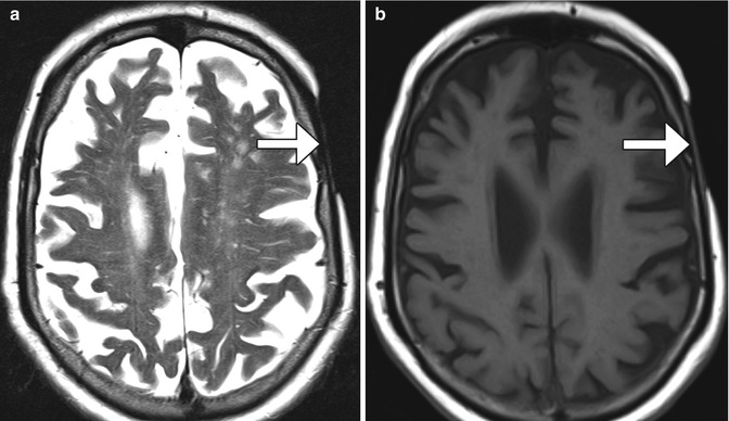
Fig. 4.6
Mohs micrographic surgery. The patient has a history of basal-cell carcinoma of the scalp. Coronal CT image shows a well-defined defect in the left scalp (encircled)
Fig. 4.7
Split-thickness skin graft. Axial T2-weighted (a) and T1-weighted (b) MR images show that the skin graft (arrows) is thinner than the adjacent normal scalp
4.5 Rotational Galeal Flap Scalp Reconstruction
4.5.1 Discussion
Galeal flaps, such as the retroauricular rotation flap, can be used to cover scalp defects as large as 60% of the scalp surface area. Galeal flaps are comprised of fascia, subcutaneous tissue, and vascular components. In the early postoperative period, a remote donor site defect can be apparent, such as with “flip-flop” flaps (Fig. 4.8). Galeal flaps can incur essentially the same complications as other types of flaps, including infection, tumor recurrence, and necrosis, as well as dehiscence and alopecia.
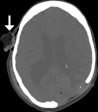
Fig. 4.8
Galeal flap, early postoperative period. The patient has a history of infected hardware, necrotic bone, and open scalp wound. A rotational scalp flap was advanced to cover the defect after wound debridement. Axial CT image shows a left parietal skull defect covered by a rotational fasciocutaneous flap. There is surgical packing material (arrow) in the contralateral donor site
4.6 Free Flap Reconstruction of Complex Scalp Defects
4.6.1 Discussion
Free flap transfer is used for repairing complex scalp defects in order to provide functional, cosmetic, and structural support when the use of skin grafts, locoregional flaps, and tissue expanders is not feasible. The latissimus dorsi myocutaneous flap is particularly useful for subtotal and total skull reconstruction, in which there is considerable dead space (Fig. 4.9). Latissimus dorsi flaps can be harvested with ribs (myo-osseocutaneous) or combined with titanium mesh for added support. Omental flaps are another option for closing large scalp and cranium defects (Fig. 4.10). These contain mostly adipose tissues and are covered by skin grafts. Other donor tissues for free flap transfer include rectus abdominis muscle flaps, scapular flap, radial forearm flap, and anterolateral thigh flap. Vascular supply is typically obtained via anastomosis to the superficial temporal artery and vein or at times the occipital artery. Complications include delayed flap failure, which requires secondary reconstruction, neck hematoma, venous thrombosis, skull base infection, large wound dehiscence, small wound dehiscence, donor site hematoma and seroma, and cerebrospinal fluid leak.
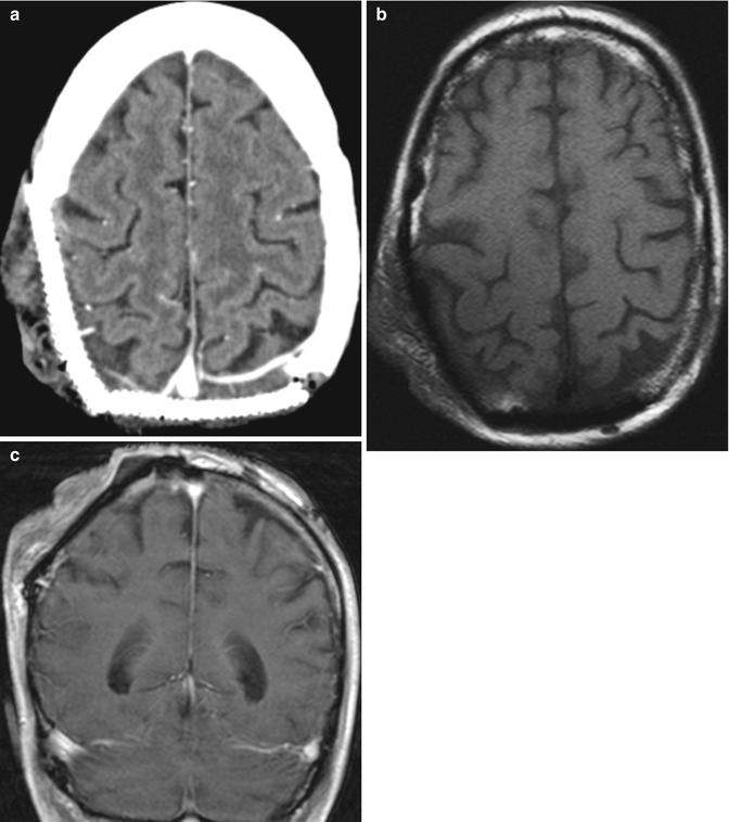
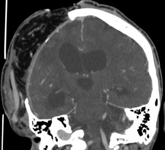
Fig. 4.9
Latissimus dorsi muscle flap. The patient has a history of extensive squamous cell carcinoma of the scalp, with invasion of the calvarium. Axial CT image (a) shows titanium cranioplasty of the right occipital and parietal regions and an overlying muscle flap. Characteristic muscle fibers are apparent in the flap on the axial T1-weighted MRI (b). Axial post-contrast Tl-weighted MRI (c) shows enhancement of at least some of the muscle fibers
Fig. 4.10
Omental free flap. The patient is status post motorcycle accident during which loss of cranial bone occurred. Coronal CT image shows the flap overlying the right hemicraniectomy site contains fat and omental vessels and is covered by skin graft
4.7 Scalp Tumor Recurrence
4.7.1 Discussion
Most recurrent tumors manifest within the first 2 years following resection and are most common in the tumor bed near the anastomosis. Imaging can detect both locoregional recurrence and the extent of intracranial extension of recurrent tumors (Fig. 4.11). Postoperative imaging can also help in distinguishing tumor recurrence from fibrosis related to the surgery or radiation therapy. Recurrent tumors typically appear as nodular foci of enhancement and have higher T2-weighted signal intensity on MRI than fibrosis.
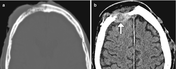
Fig. 4.11
Skin tumor recurrence. The patient has a history of locally invasive squamous cell carcinoma, presenting as a large fungating scalp lesion. Axial preoperative CT image (a) shows a right frontal scalp mass that invades the underlying skull. CT images obtained 14 months after surgery (b) show an enhancing mass (arrow) deep to the myocutaneous free flap. There are also several metastatic nodules in the left scalp
4.8 Burr Holes
4.8.1 Discussion
Burr hole craniostomy is a commonly performed maneuver as part of creating craniotomy flaps, stereotactic biopsy, hematoma decompression, ventricular endoscopic procedures, insertion of ventricular catheters, drains, and electrode insertion. Burr holes are surgical defects that traverse the full thickness of the calvarium created using various drills and can be packed with a variety of materials, such as bone wax and methyl methacrylate and may be covered with a plate (Fig. 4.12). Linear enhancement along the edges of burr holes is commonly observed as vascular granulation tissue forms, thereby potentially mimicking abscesses or neoplasms (Fig. 4.13).
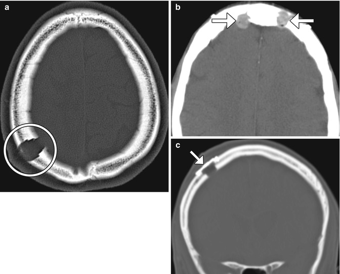
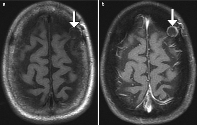
Fig. 4.12
Burr holes. Axial CT image (a) shows a right parietal calvarium defect that matches the contours of the drill (encircled). Axial CT image (b) shows methyl methacrylate filling the bifrontal burr holes (arrows). Axial CT image (c) shows a metallic burr hole cover (arrow)
Fig. 4.13
Burr hole neovascularization. Axial T1-weighted (a) and post-contrast fat-suppressed T1-weighted (b) MR images show a left frontal burr hole with marginal enhancement (arrows)
4.9 Craniotomy
4.9.1 Discussion
Craniotomy consists of opening the cranial vault by removing a bone flap during the course of surgery and replacing it at the completion of the procedure, as opposed to craniectomy in which the bone is removed and not replaced. Once the skull is exposed by raising the overlying scalp and pericranial flap, burr holes are drilled, from which the bone flap is created using a saw or drill. The bone flap is set aside during the procedure and replaced upon completion of the surgery. Some of the standard types of craniotomy include the following:
Pterional
Orbitozygomatic
Modified orbitozygomatic
Frontal or bifrontal
Parietal or biparietal
Subtemporal
Anterior parasagittal
Posterior parasagittal
Suboccipital
Retrosigmoid
Pre-sigmoid
Far lateral
Hemicraniotomy
Skin staples are often used to close the scalp flap after surgery and can be present on imaging during the early postoperative period (Fig. 4.14). A variety of devices and methods are available to secure cranial bone flaps following craniotomy. The most commonly used are microfixation plates or clamps (Fig. 4.15). Microfixation plates are often composed of titanium, which produces minimal streak or susceptibility artifact. Complications related to the presence of microfixation plates and screws, such as transcranial migration, are uncommon, except in young children, where absorbable hardware or suture may be used. Stainless steel wires threaded across the craniotomy margin to the bone plates is no longer performed in developed countries, but may still be encountered on imaging (Fig. 4.16).
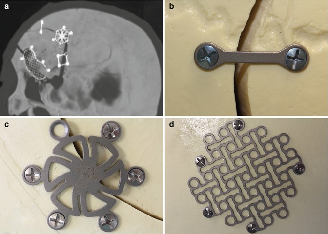
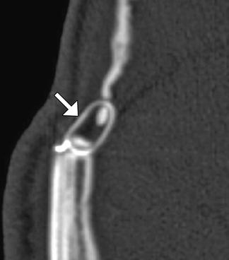
Fig. 4.14
Skin staples. Coronal CT image shows numerous staples (arrows) used to close the skin flap after craniotomy
Fig. 4.15
Microfixation plates. 3D CT image (a) shows a variety of titanium microfixation plates securing the bone flap. Photographs of a variety of low-profile fixation plates (b–d) (Courtesy of Patricia Smith and Sarah Paengatelli)
Fig. 4.16
Fixation wire. Axial CT image shows a stainless steel wire that secures the bone flap (arrow)
Hinge craniotomy is an alternative to traditional decompressive craniectomy and allows swollen brain parenchyma to expand extracranially while avoiding some of the complications associated with cranial revision. The bone flap is left attached on one side to the scalp soft tissues, usually the temporalis muscle. This results in the appearance of an outwardly displaced bone flap on CT (Fig. 4.17).
Fig. 4.17
Hinge craniotomy. Coronal CT image shows that the right parasagittal bone flap is not secured to the adjacent calvarium in order to allow the edematous brain to expand freely across the craniotomy defect
The normal imaging appearance of the craniotomy site can evolve over time. In the early postoperative period, the bone flap margins are sharp and should align precisely with the rest of the skull, unless a craniectomy was done to provide more surgical accessibility. The extent of dural enhancement that normally occurs after craniotomy ranges considerably. Dural enhancement is present in the majority of patients following cranial surgery and can be seen within the first postoperative day (Fig. 4.18). The presence and degree of enhancement are largely dependent on the time elapsed since the time of surgery and the types of substitutes used during closure, which in some cases can persist indefinitely. Dural enhancement tends to be apparent earlier and lasts longer with gadolinium-based contrast than with iodine-based contrast. Granulation tissue also normally forms along the edges of the bone flap, which manifests as linear enhancement that is often visible on MRI and often accompanies dural enhancement. This type of enhancement usually persists up to 1 year following craniotomy.
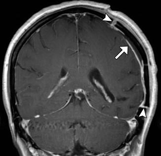
Fig. 4.18
Expected dural enhancement after craniotomy. Coronal post-contrast T1-weighted MRI shows linear dural enhancement deep to the craniotomy flap (arrow). There is also enhancement along the edges of the bone flap (arrowheads)
Pneumocephalus is the presence of intracranial air and is an expected finding after recent cranial surgery. Indeed, virtually all patients exhibit some degree of pneumocephalus during the immediate postoperative period. Pneumocephalus can be identified by air attenuation on CT and signal voids on MRI (Fig. 4.19). Regardless of the location, pneumocephalus normally resolves within 3 weeks of surgery.
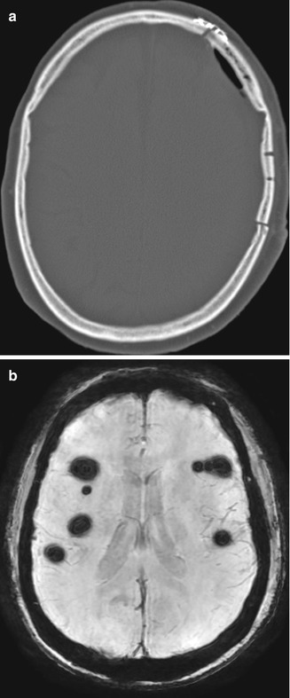
Fig. 4.19
Postoperative pneumocephalus. Axial CT image (a) shows and small amount of left frontal convexity extra-axial pneumocephalus. Axial SWI image in another patient (b) shows scattered foci of supratentorial signal voids from subarachnoid pneumocephalus after posterior fossa surgery
During the early postoperative period, typical changes also occur in the soft tissues overlying the craniotomy site, including temporalis muscle swelling (Fig. 4.20), which likely represents edema due to manipulation during surgery.
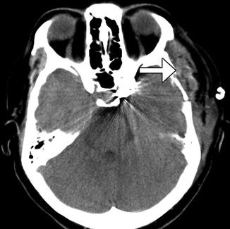
Fig. 4.20
Temporalis muscle swelling. Axial CT image obtained after recent left pterional craniotomy shows diffuse enlargement of the left temporalis muscle (arrow)
4.10 Cranioplasty
4.10.1 Discussion
Intraoperatively fashioned acrylic cranioplasty is composed of methyl methacrylate resin that can be molded to a desired shape on the surgical field. The material tends to appear heterogeneous on CT and low signal on MRI (Fig. 4.21). The material often contains multiple foci of air due to the exothermic reaction that occurs when formed. The trapped bubbles should not be confused with infection. The methyl methacrylate at times can migrate prior to hardening, the appearance of which can potentially mimic hemorrhage on CT.
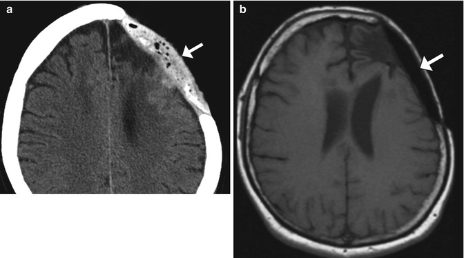
Fig. 4.21
Intraoperatively fashioned acrylic cranioplasty. Axial CT image (a) shows an acrylic cranioplasty flap containing low-attenuation bubbles (arrow). The cranioplasty plate (arrow) has low signal on the corresponding T1-weighted MRI (b)
Preformed acrylic methyl methacrylate plates are specially molded to fit individual craniectomy defects using a computer-aided design system and 3D CT data. These flaps are usually secured to the adjacent calvarium using titanium plates and are thus continuous with the calvarium. On CT, preformed acrylic plates demonstrate homogeneous intermediate attenuation, around 100 HU (Fig. 4.22). Unlike the acrylic plates prepared intraoperatively, the preformed plates do not contain air bubbles. However, the preformed acrylic plates contain holes that are drilled to promote tissue ingrowth and leave a pathway to prevent accumulation of fluid in the epidural space.
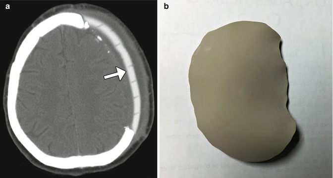
Fig. 4.22
Preformed acrylic cranioplasty. Axial CT image (a) demonstrates a high-attenuation left frontal acrylic cranioplasty (arrow), conforming to the natural contours of the calvarium. The plate is traversed by numerous holes to allow tissue ingrowth. Photograph of customized acrylic cranioplasty flap without holes (b)
Hydroxyapatite cement paste is sometimes used to close off small gaps in the calvarium. It can be molded to match the particular anatomy and can be applied in conjunction with other materials, such as titanium mesh. The cement appears as homogeneously hyperattenuating on CT, similar in attenuation as natural bone (Fig. 4.23). On MRI, the hydroxyapatite appears as a signal void.
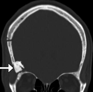
Fig. 4.23
Hydroxyapatite cement. Coronal CT image shows the hyperattenuating material (arrow) filling a gap between the craniotomy flap and the adjacent skull
Titanium mesh is commonly used as a cranioplasty material. These plates generally produce good cosmetic results and minimal discomfort. Titanium produces minimal streak artifact on CT (Fig. 4.24). Solid titanium plates are now infrequently used but may be observed on follow-up imaging (Fig. 4.25).
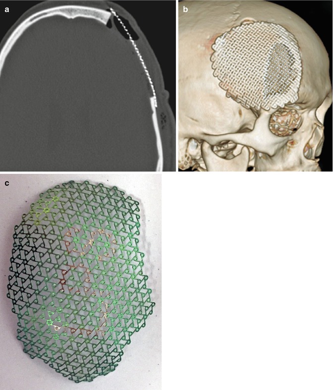
Fig. 4.24
Titanium mesh cranioplasty. Axial (a) and 3D surface rendered (b) CT images show a titanium mesh that spans a left frontal craniectomy defect. Photograph (c) of a titanium mesh (Courtesy of Caroline Dufault, RN)
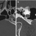
Fig. 4.25
Titanium plate. Axial CT image shows the metal attenuation plate (arrow) that spans the left retrosigmoid craniectomy, which was performed in the 1980s
Porous polyethylene implants are also suitable for covering cranial defects. This type of implant is also custom created for each patient using a computer-aided design system and 3D CT data. The material enables soft tissue and bone ingrowth and displays low attenuation on CT and low signal intensity on T2- and T1-weighted MRI sequences (Fig. 4.26).
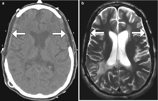
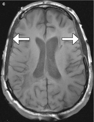
Fig. 4.26
Porex (porous polyethylene) cranioplasty. Axial CT image (a) shows bilateral low-attenuation implants (arrow). The cranioplasty material also displays low signal on T2-weighted (b) and T1-weighted (c) MR images
Synthetic bone grafts that are biocompatible have been developed for cranioplasty. For example, Bioplant HTR Synthetic Bone is a microporous composite of poly(methyl methacrylate) (PMMA), polyhydroxyethylmethacrylate (PHEMA), and calcium hydroxide. On CT, the HTR cranioplasty appears as heterogeneous with an overall attenuation that is greater than soft tissue but lower than bone (Fig. 4.27).
Fig. 4.27
Synthetic (HTR) bone graft cranioplasty. Coronal CT image shows right hemicraniectomy with heterogeneously hyperattenuating cranioplasty material (arrow)
Autologous bone grafts can also be used for cranioplasty. These are often used in the form of split calvarial grafts in which the inner table is separated from the outer table in order to increase surface area for maximal coverage of a craniectomy defect (Fig. 4.28).
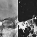
Fig. 4.28
Split-thickness bone graft cranioplasty. Initial 3D CT image (a) shows a right temporal skull defect (*). 3D CT image after cranioplasty (b) shows interval harvesting of bone from the right parietal calvarium and repositioning it into the temporal skull defect (curved arrow). Corresponding coronal CT image (c) shows the split calvarium at the donor site (arrow) and the repositioned split calvarial graft in the right temporal region (encircled)
4.11 Autocranioplasty
4.11.1 Discussion
Several options are available for storing autologous bone flaps after decompressive craniectomy for delayed autocranioplasty. Often, bone flaps are stored in a sterile freezer. This approach preserves the bone flap very well, providing good cosmetic results. An alternative is subcutaneous storage, which allows the bone flap to stay with the patient and may decrease the risk of devitalization and/or infection of the flap. Bone flaps can be kept fresh by implanting them into subcutaneous pockets in the abdomen and may be encountered on imaging (Fig. 4.29). Bone grafts stored in this manner tend to undergo remodeling.
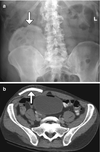
Fig. 4.29
Autocranioplasty. Frontal radiograph (a) and axial CT image (b) show a skull flap (arrows) embedded within the right lower quadrant subcutaneous tissues
4.12 Craniectomy, the Meningogaleal Complex, and Suboccipital Craniectomy
4.12.1 Discussion
Decompressive craniectomy is performed in order to decrease intracranial pressure when medical management alone is insufficient and is most commonly used in the setting of traumatic brain injury, subarachnoid hemorrhage, intraparenchymal hemorrhage, and cerebral infarction. The procedure consists of removal of portions of the skull, which is not replaced during the procedure. Hemicraniectomy is performed when one side of the brain is affected and usually entails removal of bone in the frontoparietotemporal region. On the other hand, bilateral (bifrontal) craniectomy is performed when both sides of the brain are affected and consists of removing the calvarium of the anterior cranial fossa to the coronal sutures.
Decompressive craniectomy has characteristic imaging findings. Following craniectomy, the galea aponeurotica becomes juxtaposed against the dura. Scar tissue then forms between these two layers, which creates the meningogaleal complex beneath the subcutaneous tissues. Normally, this complex measures between 2 and 6 mm in thickness. On CT, the meningogaleal complex is slightly hyperattenuating, while the appearance on MRI is variable depending on the degree of hypervascular tissue that is incorporated (Fig. 4.30). Smooth, uniform enhancement is expected on CT and MRI.
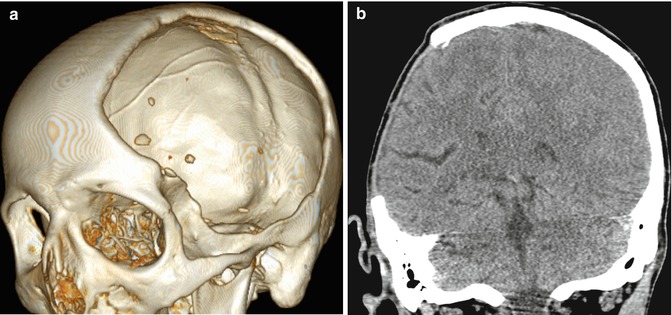
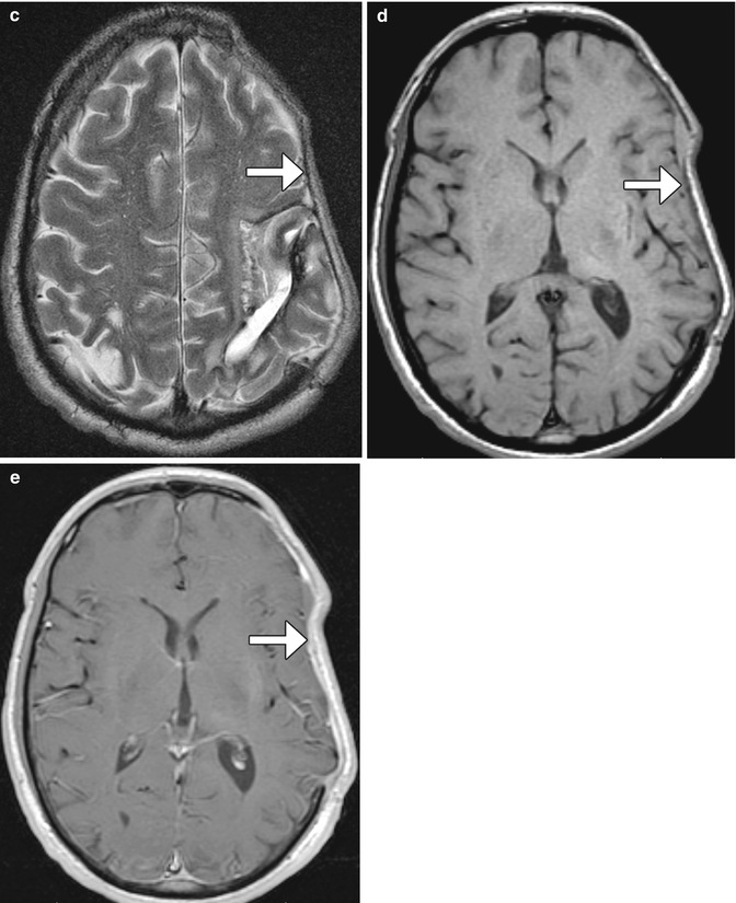
Fig. 4.30
Craniectomy and normal meningogaleal complex.3D (a) and coronal (b) CT images show a large right hemicraniectomy defect and a normal meningogaleal complex in which the dura is juxtaposed to the scalp. Axial T2-weighted (c), T1-weighted (d), and post-contrast T1-weighted (e) MRI sequences in a different patient show enhancement of the left hemicraniectomy meningogaleal complex (arrows)
4.13 Cranial Vault Surgical Remodeling for Craniosynostosis
Sagittal synostosis is a relatively common type of craniosynostosis that results from premature fusion of the sagittal suture. Surgery is performed for relieving associated elevated intracranial pressure and for cosmesis. There are several approaches to correcting the deformity including bone removal and reshaping with barrel stave osteotomies (Fig. 4.31), endoscopic craniectomy with adjuvant use of a remodeling helmet, and placement of distraction devices. Follow-up imaging may be obtained for planning additional surgical reconstruction or if complications are suspected.
Correction cranioplasty and orbitofrontal advancement is a treatment option for trigonocephaly. This procedure generally entails take down of a bifrontal bone flap, removal of the orbital bandeau, followed by cranial vault reconstruction and advancement (Fig. 4.32). The use of reabsorbable fixation plate and screws yields superior cosmetic results and can appear as tiny bone defects without discernible radio-attenuating components otherwise on CT. The orbitofrontal advancement procedure can be augmented using onlay cements (Fig. 4.33). The incidence of complications is about 2%, and there is a 12% reoperation rate. Residual hypotelorism usually autocorrects, while bitemporal depressions may develop over time. High-resolution craniofacial CTs with 3D reformatted images are particularly useful for postoperative assessment and planning additional surgical intervention, if needed.
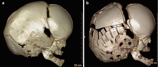
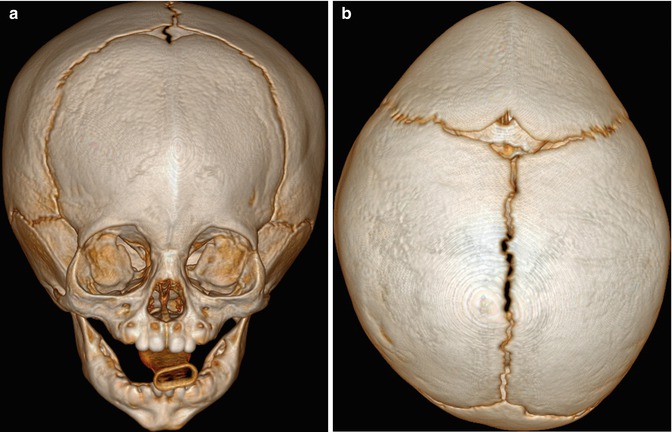
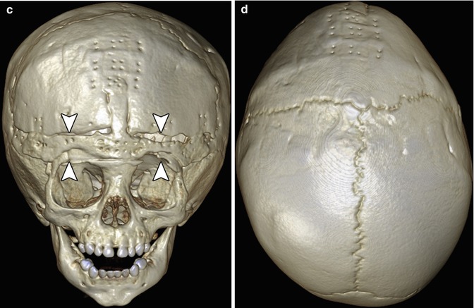
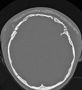
Fig. 4.31
Barrel stave osteotomies and cranial remodeling for scaphocephaly. Preoperative 3D CT image (a) shows dolichocephaly. Postoperative 3D CT image (b) demonstrates multiple parietal barrel stave osteotomies, resulting in improved skull morphology
Fig. 4.32
Correction cranioplasty and orbitofrontal advancement. The patient has a history of nonsyndromic trigonocephaly. Preoperative frontal (a) and top view 3D CT (b) images show fusion of the metopic suture, with prominent frontal beaking. Postoperative frontal (c) and top view 3D CT (d) images show osteotomies along the orbital bandeau (arrowheads). The multiple tiny holes in the calvarium correspond to the attachment sites of the absorbable plates, which are otherwise not visible
Fig. 4.33
Orbitofrontal advancement surgery with onlay cement. Axial CT image shows the hyperattenuating artificial bone cement superficial to the reconstructed frontal bone. The presence of seroma displaces the cement away from the surface of the calvarium and bifrontal craniotomies
Management of raised intracranial pressure in syndromic multi-suture craniosynostosis by cranial vault expansion can be achieved by posterior calvarial vault expansion using distraction osteogenesis (Fig. 4.34).
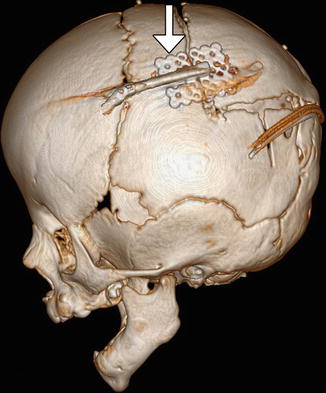
Fig. 4.34
Posterior cranial vault distraction. Lateral 3D CT image of the skull shows parietal osteotomies with a distraction device in position (arrow)
Endoscopic craniosynostosis repair is a minimally invasive treatment option available to patients under 6 months of age. The technique consists of performing a strip craniectomy, whereby the affected suture is resected (suturectomy). This results in a linear gap along the course of the suture and allows the calvarium to be remodeled with postoperative helmet therapy (Fig. 4.35). Endoscopic-assisted wide-vertex craniectomy and barrel stave osteotomies can also be performed.
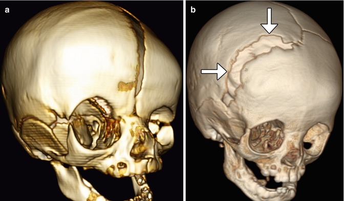
Fig. 4.35
Endoscopic strip craniectomy. Preoperative 3D CT image (a) shows asymmetric right coronal synostosis, resulting in deformity of the calvarium. Postoperative 3D CT image (b) shows interval resection of the right coronal suture (arrows), resulting in improved contours of the skull
Calcium phosphate cement has been used to fill bony defects created during cranial remodeling surgery for craniosynostosis repair in the pediatric population and is intended to be osteoconductive. The bone cement initially has a putty-like consistency and can be applied in an inlay or onlay fashion. The material can undergo bioresorption and generally does not impede the actively growing calvarium. On CT, calcium phosphate cement appears as hyperattenuating with respect to bone (Fig. 4.36). The appearance of the junction between the native bone and the bone cement is variable, ranging from a sharp interface to a lucent gap when resorption occurs. The bone cement tends to be brittle and can also fragment. The presence of bone cement fragmentation does not necessarily imply palpable motility and is not particularly problematic if fragmentation occurs as an onlay.
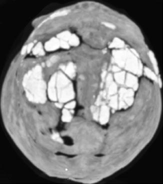
Fig. 4.36
Calcium phosphate cement for craniosynostosis repair. 3D CT image shows several areas of the hyperattenuating cement used to fill the craniectomy defects
4.14 Cranial Vault Encephalocele Repair
4.14.1 Discussion
Traditional management of encephaloceles consists of resecting the abnormal herniated brain tissue and closing the wound via primary intention if there is sufficient skin available (Fig. 4.37), with the goal of avoiding new deficits related to extended surgery. Cranioplasty can be performed at the same time as the primary surgery or at a later time, using materials such as methyl methacrylate, hydroxyapatite bone cement, demineralized bone matrix, and autologous grafts, which can be harvested from the adjacent calvarium, for example (Fig. 4.38). If a substantial amount of functional brain tissue has herniated through the encephalocele sac, expansile cranioplasty can be performed. This technique consists of reconstructing the calvarial defect with autologous bone graft harvested from the adjacent parietal region. This approach effectively enlarges or extends the intracranial cavity to encompass the herniated brain tissue.
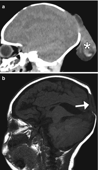
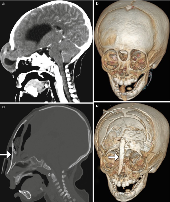
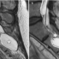
Fig. 4.37
Occipital encephalocele resection and primary closure. Preoperative sagittal CT image (a) shows herniation of dysplastic brain tissue (*) through a posterior calvarial defect. Postoperative sagittal T1-weighted MRI (b) shows interval resection of the herniated brain tissue and closure of the defect via duraplasty and skin (arrow)
Fig. 4.38
Frontonasal encephalocele repair. Preoperative sagittal (a) and 3D (b) CT images show a frontonasal encephalocele herniating through a midline skull defect. Postoperative sagittal (c) and 3D (d) CT images show interval resection of the encephalocele and repair of the defect using calvarial bone graft (arrows)
4.15 Box Osteotomy
Hypertelorism can be corrected by performing box osteotomy, which involves creating a frontal bone flap to help remove excess interorbital bone and to mobilize the orbits. Once the orbits are repositioned closer to one another, they can be secured with plates and screws (Fig. 4.39).
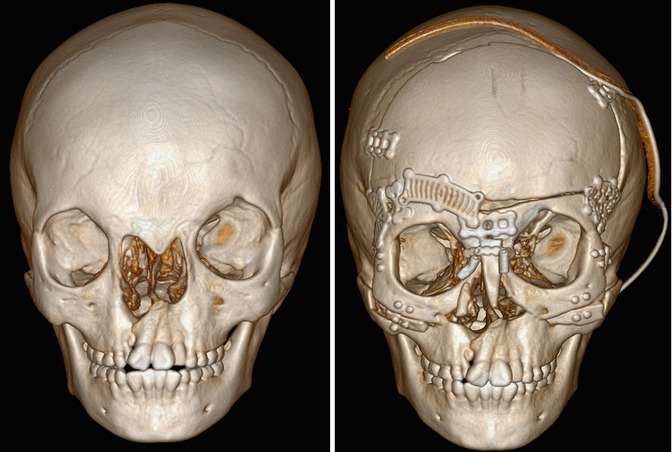
Fig. 4.39
Box osteomtomy. Preoperative 3D CT image (a) shows craniofacial dysplasia with hypertelorism. Postoperative 3D CT image (b) shows interval medial repositioning of the orbits and reconstruction of the nose with bone graft
4.16 Absorbable Hemostatic Agents
4.16.1 Discussion
Several types of topical absorbable hemostatic agents are available for neurosurgical procedures, including cellulose-, gelatin-, and collagen-based agents and thrombin and fibrin glue.
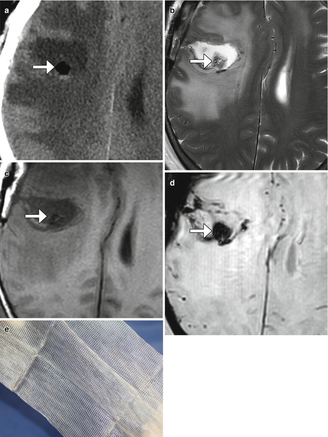
Oxidized regenerated cellulose, such as Surgicel, is available in the form of a fabric that can be used to line the margins of resection cavities or packed tightly to control a more focal source of bleeding. Implanted oxidized cellulose has been reported to mimic abscesses and masses on postoperative imaging. On CT, oxidized cellulose often displays low attenuation, and on MRI, it usually shows low signal on T2, but variable T1 signal (Fig. 4.40). Sometimes, the presence of high T1 signal can potentially mimic residual tumor on contrast-enhanced images. The hemostatic agent ultimately resorbs over the course of months.
 Imaging of the Postoperative Skull Base and Cerebellopontine Angle
 Imaging of Cerebrospinal Fluid Shunts, Drains, and Diversion Techniques
 Imaging the Paranasal Sinuses and Nasal Cavity
 Imaging of Vascular and Endovascular Surgery
 Imaging of the Postoperative Ear and Temporal Bone
 Imaging of Postoperative Spine


Related posts:
Imaging of the Postoperative Skull Base and Cerebellopontine Angle
Imaging of Cerebrospinal Fluid Shunts, Drains, and Diversion Techniques
Imaging the Paranasal Sinuses and Nasal Cavity
Imaging of Vascular and Endovascular Surgery
Imaging of the Postoperative Ear and Temporal Bone
Imaging of Postoperative Spine
Stay updated, free articles. Join our Telegram channel
Full access? Get Clinical Tree
