Fig. 8.1
The patient has a history of conductive hearing loss due to aural atresia. Lateral scout image (a) shows the BAHA device in position (arrow). Axial CT image (b) shows the screw embedded in the temporal bone (arrow) and the overlying abutment (arrowhead). Photograph of BAHA device components (c) (Courtesy of Cochlear Corp)
8.2 Auriculectomy
8.2.1 Discussion
Auriculectomy consists of resection of all or part of the pinna. This procedure is usually performed for resection of external ear cutaneous malignancies, such as basal cell carcinoma or squamous cell carcinoma. Parotidectomy and neck dissection may be performed in conjunction with auriculectomy if there is extension of tumor along the fascial planes or if regional lymph node metastasis is suspected. In addition, lateral temporal bone resection is often performed if there is extension of tumor from the outer pinna into the external auditory canal. Depending upon the extent of resection, the resulting surgical defect can be closed primarily (Fig. 8.2) or via a variety of reconstruction techniques using skin grafts or soft tissue flaps (Fig. 8.3), for example. Furthermore, auricular prostheses can also be applied for cosmetic purposes, and these may be held in place with osseointegrated magnetic implants (Vistafix, Cochlear Corporation, Australia). Ultimately, postoperative imaging, particularly CT or MRI, is typically obtained to evaluate for tumor recurrence in this group of patients.
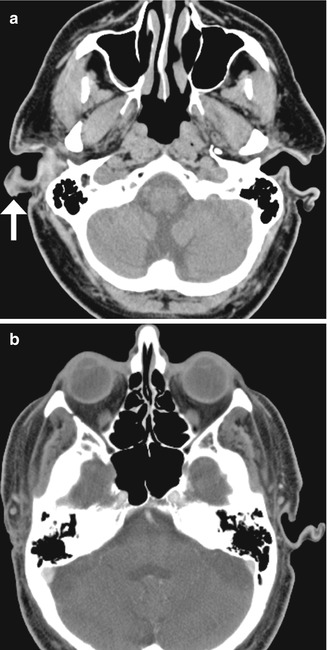
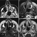
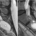
Fig. 8.2
Auriculectomy. Axial CT image (a) shows a right auricular squamous cell carcinoma (arrow). Postoperative axial CT image (b) shows complete absence of the right auricle
8.3 Auricular Reconstruction
8.3.1 Discussion
Ear reconstruction is performed to reproduce the normal appearance of the auricle for conditions such as microtia. Autogenous rib cartilage reconstruction has been one of the more traditional methods. The cartilage grafts often appear calcified (Fig. 8.3). High-density porous polyethylene (Medpor) is a more recent option. Medpor is a stable alloplastic implant material that can integrate with host tissues and is relatively resistant to infection. For auricular reconstruction, the prosthesis is enveloped in a temporoparietal fascial flap with full-thickness skin graft coverage in order to provide good cosmetic results and minimize the risk of implant extrusion. On CT, Medpor ear prostheses demonstrate attenuation values between fat and soft tissue and are shaped to resemble the natural morphology of the auricle (Fig. 8.4).
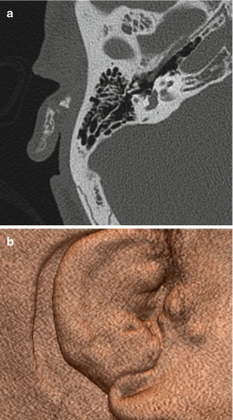

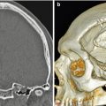
Fig. 8.3
Auricular reconstruction with rib graft. Axial (a) and 3D (b) CT images show cartilage and bone fragments within the remodeled right auricle
Fig. 8.4
Auricular reconstruction with porous polyethylene. Coronal (a) and sagittal (b) CT images show a low-attenuation left auricular implant that has near-anatomic configuration
8.4 Canaloplasty and Meatoplasty
8.4.1 Discussion
Canaloplasty and meatoplasty consist of surgically widening the bony external auditory canal and soft tissue/cartilaginous meatus, respectively. This can be performed for treating congenital or acquired canal stenosis and other lesions such as exostoses. Canaloplasty is also often performed as part of a transcanal approach in order to augment surgical exposure during middle ear surgery. Meatoplasty is often performed in conjunction with canal wall down mastoidectomy to provide postoperative access to the resultant mastoid cavity for evacuation of debris in the office. The resulting appearance on CT is an external auditory canal with a relatively capacious lumen (Fig. 8.5). In particular, thinning, irregularity, and/or flattening of the bone, soft tissue thickening, and bony wall defects are common findings on postoperative imaging and should not be mistaken for pathology. Complications of canaloplasty include canal restenosis, temporomandibular joint violation, osteonecrosis, and facial nerve palsy—especially if the distal aspect of the mastoid portion of the facial nerve courses lateral to the tympanic annulus thereby being at risk of drill trauma in the posterior-inferior aspect of the external auditory canal. If persistent pain, trismus, or delayed healing is encountered after canaloplasty, radiologic assessment of the integrity of the anterior canal wall is made to determine if the temporomandibular joint has been violated and assessment of whether this has resulted in a prolapse of joint capsule into the canal lumen. Chronic otitis externa and failed epithelialization after canaloplasty may suggest the possibility of iatrogenic osteonecrosis from excessive burning of the bone by a drill bur that was applied with insufficient irrigation, which will appear as a lytic defect on CT.
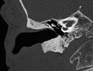
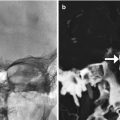
Fig. 8.5
Canaloplasty and meatoplasty. Coronal CT image shows a capacious meatus and external auditory canal with straightening of the floor and loss of the inferior tympanic sulcus
8.5 Atresiaplasty
8.5.1 Discussion
Atresiaplasty consists of creating an external auditory canal and tympanic membrane in order to restore hearing in selected patients with congenital external aural atresia. An opening is drilled through the atresia plate, a new tympanic membrane is usually created using temporalis fascia, and the external auditory canal is often lined with split-thickness skin grafts (Fig. 8.6). Complications of the procedure include external auditory canal restenosis, lateralization and perforation of the tympanic membrane, ossicular chain refixation, sensorineural hearing loss, facial nerve injury, and cholesteatoma, usually in the created external auditory canal, which appears as globular soft tissue on CT, sometimes with associated bone erosions (Fig. 8.7).
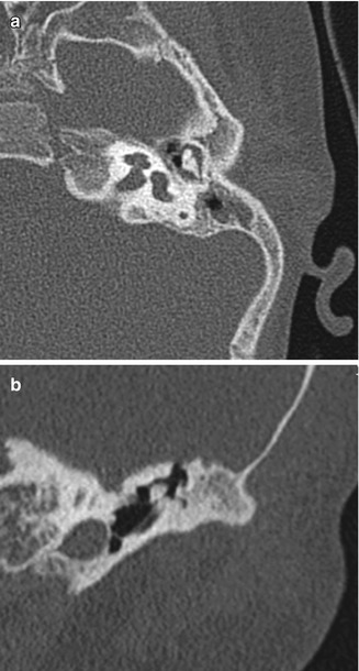

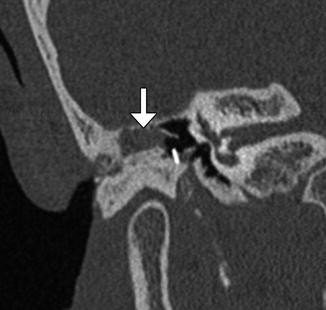
Fig. 8.6
Atresiaplasty. Preoperative axial (a) and coronal (b) CT images show bony atresia of the left external auditory canal with intact ossicles. Postoperative axial (c) and coronal (d) CT images show interval resection of the atretic plate and partial mastoidectomy, resulting in a passage that communicates with the exterior and neotympanic membrane
Fig. 8.7
Cholesteatoma after atresiaplasty. Coronal CT image shows soft tissue material (arrow) within the surgically created external auditory canal, which proved to be a cholesteatoma. There is also scar tissue that tethers the ossicular prosthesis in an abnormal position
8.6 Myringotomy and Tympanostomy Tubes
8.6.1 Discussion
Tympanostomy tubes (pressure equalization tubes) are commonly used to treat the manifestations of Eustachian tube dysfunction including recurrent acute otitis media or chronic otitis media with effusion by providing an alternative outlet for middle drainage and intratympanic pressure equalization via the external auditory canal. Tube placement follows myringotomy, in which an opening is made in the tympanic membrane. Tympanostomy tubes are available in a variety of shapes, sizes, and materials, including plastics and metals, which are readily apparent on CT (Figs. 8.8, 8.9, and 8.10). However, the presence of fluid or malpositioning may make identification of these tubes difficult. The tubes may be found incidentally on CT. Thus, recognizing tympanostomy tubes on imaging is important as to not confuse these with unintended foreign bodies or ossicular dislocation. CT may also be performed to confirm the presence of tympanostomy tubes that are not readily visible on physical exam and to evaluate for suspected complications, such as persistent effusions within the middle ear or mastoid, cholesteatoma, or diffuse tympanosclerosis (Fig. 8.11). Occasionally a tube may be detected in the middle ear space due to a rare incidence of medial migration, but more often a result of accidental loss of a tube within the middle ear during placement. Tympanostomy tubes are normally expelled spontaneously from the tympanic membrane after 3–24 months (Fig. 8.12) depending on the design and shape of the particular tube utilized. The main complications of tympanostomy tubes include formation of a foreign body granuloma on the tympanic membrane immediately adjacent to the tube or chronic otorrhea due to unresolved underlying chronic otitis media or mastoiditis.

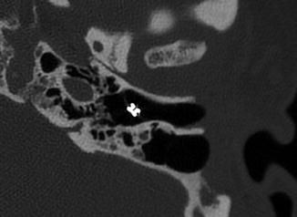
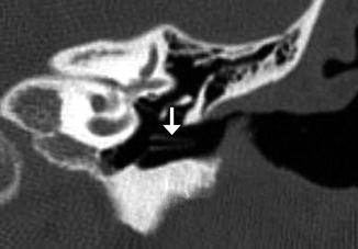
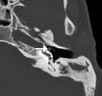
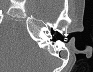
Fig. 8.8
Plastic grommet. Axial CT image shows a Teflon grommet appropriately situated across the tympanic membrane
Fig. 8.9
Metal grommet. Axial CT image shows a metal grommet in the tympanic membrane
Fig. 8.10
Plastic shaft tympanostomy tube. Coronal CT image shows a long shaft Teflon tube (arrow)
Fig. 8.11
Medial dislocation of tympanostomy tube. Axial CT image shows a tympanostomy tube in the hypotympanum (arrow). Note the myringotomy, which appears as a gap in the tympanic membrane
Fig. 8.12
Extrusion of tympanostomy tube. Axial CT image shows a tympanostomy tube in the external auditory canal (arrow)
8.7 Myringoplasty and Tympanoplasty
8.7.1 Discussion
Myringoplasty is a simple procedure that is limited to tympanic membrane repair without exploration or manipulation of the middle ear space. Myringoplasty is most often applied to very small tympanic membrane defects caused by extruded tympanostomy tubes. In contrast, tympanoplasty involves reconstruction of the tympanic membrane with concurrent middle ear exploration and possible ossicular chain reconstruction. Several types of tympanoplasty procedures can be performed, which are depicted in Figs. 8.13, 8.14, 8.15, 8.16, 8.17, 8.18, 8.19, and 8.20 and described in Table 8.1. Among these, Type 1 and Type 3 tympanoplasties are overwhelmingly the most commonly performed. Some forms of mastoidectomy may be performed concurrent with tympanoplasty if chronic suppurative otitis media and/or cholesteatoma is present.
The most common materials used for tympanoplasty include autologous temporalis fascia and auricular cartilage grafts—with the later gaining progressive popularity among ear surgeons when dealing with chronic middle ear disease due to their resistance to the effects of negative middle ear pressure. Tympanoplasty grafts appear slightly thicker than the normal native tympanic membranes, especially if cartilage is utilized. However, excessive thickness may signify scarring within the middle ear or postoperative myringitis. Silastic sheeting is sometimes implanted during tympanoplasty in order to prevent the formation of adhesions as part of a staged surgical process wherein removal is performed months later during a second-stage middle ear exploration and ossicular chain reconstruction procedure.
High-resolution CT is the main imaging modality used for studying the architectural changes from tympanoplasty and evaluating suspected causes of graft failure and persistent conductive hearing loss, such as recurrent perforation, middle ear effusion, tympanosclerosis affecting the ossicular chain, tympanic membrane lateralization, and tympanic membrane blunting. The latter two of these are more likely to be encountered if canaloplasty was performed at that same time as tympanic membrane repair or if the malleus has been completely removed.
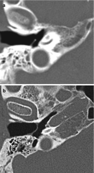
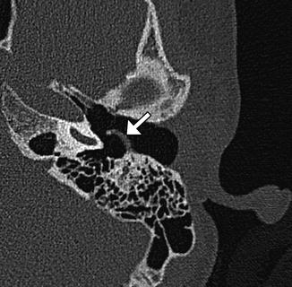
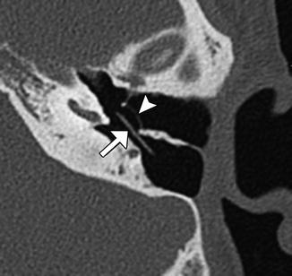
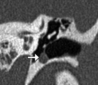
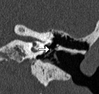
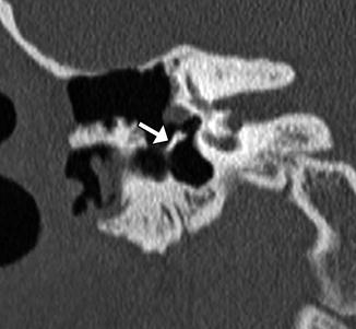
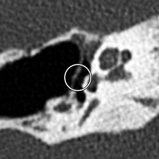
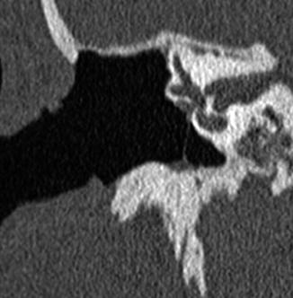
Fig. 8.13
Type I tympanoplasty with temporalis fascia. The patient has a history of long-standing right-sided tympanic membrane perforation. Since the patient was a possible candidate for cochlear implantation, repair of the tympanic membrane perforation was necessary. Preoperative axial CT image (a) demonstrates a perforation of the right tympanic membrane. Axial CT image obtained after tympanoplasty (b) shows a tympanic membrane graft composed of temporalis fascia, which is slightly thicker than native tympanic membrane
Fig. 8.14
Type I tympanoplasty with cartilage graft. Axial CT image shows the reconstructed posterior portion of the left tympanic membrane as a thick sheet (arrow). Note the relative thickness of the normal anterior portion of the tympanic membrane
Fig. 8.15
Type I tympanoplasty with silastic implant for preventing adhesions. Axial CT image shows the implant (arrow) inserted into the middle ear cavity, medial to the reconstructed tympanic membrane (arrowhead)
Fig. 8.16
Iatrogenic intratympanic cholesteatoma following tympanoplasty. Coronal CT image shows expansile soft tissue (arrow) along the inferior tympanic annulus, splaying the tympanic membrane graft
Fig. 8.17
Type II tympanoplasty. Coronal CT image shows the long process of the incus (arrow) in contact with the tympanic membrane graft
Fig. 8.18
Type III tympanoplasty minor columella with bone strut. Coronal CT image shows a bone graft (arrow) interposed between the tympanic membrane and stapes head
Fig. 8.19
Type III tympanoplasty stapes columella. Axial CT image demonstrates a reconstructed tympanic membrane with cartilage graft applied directly to the head of the stapes (encircled)
Fig. 8.20
Type IV tympanoplasty. Coronal CT image shows the tympanic membrane graft applied to the stapes footplate such that the footplate is exteriorized into the mastoid cavity and external auditory canal. Note the small middle ear space (cavum minor) created during Type IV tympanoplasty
Table 8.1
Wullstein classification of types of tympanoplasty
Type | Description | Diagram |
|---|---|---|
I | Repair of the tympanic membrane without altering the ossicles. Most common type performed |  |
II | Repair of the tympanic membrane with drumhead reconstructed onto intact incus (malleus usually absent). This procedure is only rarely performed |  |
III | Repair of the tympanic membrane and ossicular chain in a manner that couples the stapes to the drumhead. Variations include minor columella (usually a PORP prosthesis or sculpted incus interposition autograft) where drumhead is connected to intact stapes superstructure major columella, usually a TORP prosthesis, where the drumhead is connected to stapes footplate without intact superstructure, or stapes columella where drumhead is placed directly upon the intact stapes superstructure |  |
IV | Tympanic membrane repair graft is applied directly to the stapes footplate such that it is exteriorized into the ear canal while shielding of the round window niche using a thick graft, resulting in small middle ear space termed cavum minor. Usually performed along with canal wall down mastoidectomy |  |
V | Same as type IV tympanoplasty except stapes footplate is removed and oval window is sealed with soft tissue graft. Performed when the stapes footplate is ankylosed |  |
8.8 Ossicular Interposition
8.8.1 Discussion
Ossicular interposition grafting is a form of ossicular reconstruction (Type 3 tympanoplasty mechanism) that consists of resecting the malleus head or incus and then reinserting it between the stapes and either the malleus manubrium or tympanic membrane after it has been sculpted with a drill bur. The most common form of this technique is incus interposition grafting, in which the long process is amputated and a notch is cut into the short process such that it can be wedged between the manubrium of the malleus and the stapes superstructure (Fig. 8.21). If the stapes superstructure is absent, the long process of the incus is positioned in contact with the stapes footplate, and the notched short process is positioned below the manubrium (notched incus with long process); however, results of incus interposition are much poorer if the stapes superstructure is absent and the technique is only rarely utilized. The malleus head can also be used as an interposition graft by drilling a small groove at the point where the head was amputated from the malleus neck, thereby allowing the graft to be set securely between the stapes superstructure and the undersurface of the tympanic membrane. Complications related to ossicular interposition include encasement by granuloma, iatrogenic cholesteatoma, graft necrosis (Fig. 8.22), and graft dislocation (Fig. 8.23).
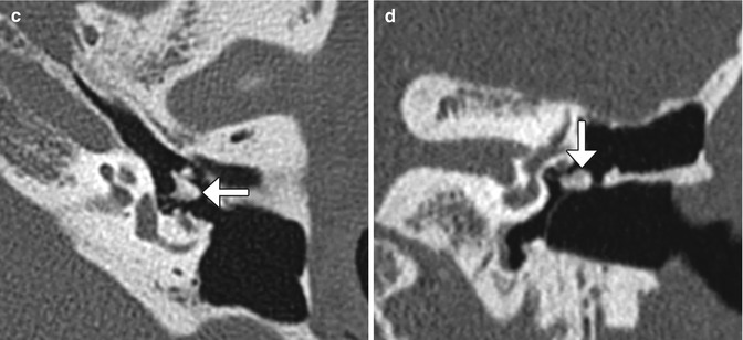
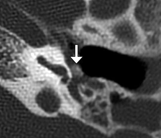
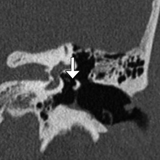
Fig. 8.21
Incus interposition. Illustration of incus interposition (a). Axial (b) CT image shows that only the malleus is present in the epitympanic space due to disarticulation of the malleoincudal joint. Axial (c) and coronal (d) CT images show that the sculpted incus (arrows) articulates with the head of the stapes
Fig. 8.22
Osteonecrosis of incus interposition graft. Axial CT image shows a demineralized incus interposition graft (arrow)
Fig. 8.23
Incus interposition dislocation. Coronal CT image shows an air gap between the head of the stapes and the remodeled incus (arrow)
8.9 Ossicular Reconstruction with a Synthetic Prosthesis: Partial Ossicular Reconstruction Prosthesis (PORP), Total Ossicular Reconstruction Prosthesis (TORP), Incudostapedial Joint Reconstruction Prosthesis, and Vibrating Ossicular Reconstruction Prosthesis
8.9.1 Discussion
PORPs and TORPs are synthetic implants used for ossicular chain reconstruction typically composed of a head to engage the tympanic membrane and a shaft to engage the stapes. Most modern prostheses are composed of dense hydroxyapatite, titanium, or some combination of the two. Hydroxyapatite has the advantage of being compatible with direct contact to the tympanic membrane, whereas titanium has a tendency to erode through the drumhead if directly in contact; therefore, an overlying protective cartilage cap is mandatory if a titanium head is utilized and optional with hydroxylapatite. On CT, cartilage appears as a thickened segment of tympanic membrane overlying the prosthesis. Plastipore, Teflon, polyethylene, stainless steel, gold, platinum, nitinol, and cortical bone have also been used. Some PORPs and TORPs feature a notched head that is intended to stabilize the implant by engaging the malleus manubrium, while others are placed in direct contact with the posterior/superior quadrant of the tympanic membrane. PORPs extend to the head of the intact stapes and are set upon the superstructure with an open cradle located at the end of the shaft. TORPs extend from the tympanic membrane to the stapes footplate where a cylindrical distal end of the shaft is set (Fig. 8.24). Occasionally a separate “footplate shoe” prosthesis is used in combination with a TORP to prevent it from slipping off of the footplate, since TORPs are often considered less secure than PORPs. A final class of incudostapedial joint reconstruction prosthesis exists to deal with the common scenario of isolated incus erosion involving the long process—including its articulation with the stapes superstructure. These prostheses can be observed spanning from the residual incus long process to the stapes capitulum. However, synthetic hydroxylapatite bone cement products are also commonly utilized for this purpose. Selected examples of various prostheses are shown in Figs. 8.25, 8.26, 8.27, 8.28, and 8.29 and listed in Table 8.2.
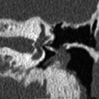

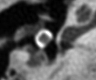
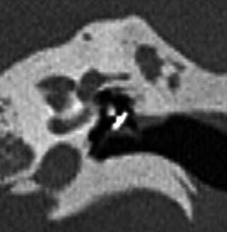
Table 8.2
Examples of ossicular prostheses
Prosthesis | Description |
|---|---|
Applebaum | Hydroxylapatite incudostapedial joint reconstruction prosthesis spanning from the incus long process to stapes head. Features a characteristic L-shaped configuration |
Black oval top | Available as PORP or TORP. Features a bulky head with a “horseshoe” or C shape |
Dornhoffer | Available as PORP or TORP with notched hydroxylapatite head and a titanium shaft |
Goldenberg | Available as PORP or TORP. Triangular notched hydroxylapatite head with off-centered Plastipore shaft |
Fig. 8.24
Schematics of PORP (a) and TORP (b). The PORP inserts between the tympanic membrane or cartilage graft complex and the head of the stapes. In contrast, the TORP inserts between the tympanic membrane or cartilage graft complex and the stapes footplate at the oval window. Photographs of various ossicular prostheses (c) (Courtesy of Grace Medical)
Fig. 8.25
Cortical bone sculpted TORP. Coronal CT image shows a linear bone fragment that extends between the tympanic membrane cartilage graft and stapes footplate
Fig. 8.26
Goldenberg TORP. Coronal CT image shows the flathead prosthesis attached to the tympanic membrane with cartilage graft reconstruction and shaft well seated upon the stapes footplate
Fig. 8.27
Applebaum PORP. Axial (a) and coronal (b) CT images show the characteristic hollow L-shaped hydroxyapatite prosthesis, which articulates with the stapes medially and incus laterally
Fig. 8.28
Black oval-top PORP. Axial CT image shows the tympanic membrane and tragal cartilage graft draped over the C-shaped hydroxyapatite head of the prosthesis. The piston of the prosthesis, which articulates with the head of the stapes, is not conspicuous
Fig. 8.29
Dornhoffer PORP. Stenver reformatted CT image shows the hydroxyapatite head in contact with the reconstructed tympanic membrane and the titanium cradle in contact with the stapes superstructure
Vibrating ossicular reconstruction prostheses (VORPs) are part of an electronic implantable hearing device (Vibrant Soundbridge, Med-El, Austria) that may be used to treat conductive hearing loss in cases where the prognosis for a favorable hearing outcome with a PORP or a TORP is extremely poor, such as severe congenital middle ear anomalies or end-stage middle ear disease. A VORP can also be used in cases of mixed hearing loss where the amplification needs are beyond the capability of a conventional hearing aid. VORPs consist of an external sound processor that is held magnetically over an implanted receiver-stimulator located under the postauricular scalp. The receiver-stimulator is connected by a wire to a magnetic vibrating floating mass transducer that is either connected to the ossicular chain or placed directly onto the round window membrane (Fig. 8.30).
Fig. 8.30
VORP. The illustration (a) shows the components of the VORP including the floating mass transducer (arrow) in the round window niche attached to the incus. Axial CT image (b) shows the floating mass transducer in the round window niche (arrow) (Courtesy of Christine Toh, MD)
8.10 Stapedectomy, Stapedotomy, and Stapes Prosthesis
8.10.1 Discussion
Stapes reconstruction is performed for treatment of conductive hearing loss in patients with otosclerosis, stapes fracture, adhesions, or tympanosclerosis. Stapedectomy usually consists of resecting the entire stapes, while stapedotomy involves removing the superstructure and creating a small hole into the stapes footplate. Stapedotomy often involves minimally traumatic surgical techniques, such as hands-free laser application.
Stapes prostheses typically extend from the incus to the stapedotomy defect in the footplate and ideally do not extend medially into the vestibule more than 0.25 mm. Several types of stapes prostheses are available, but most fall into the categories of being either a bucket or piston (Fig. 8.31). Bucket prostheses are set just under the lenticular process of the incus with a small wire that secures it, while pistons usually consist of a smaller barrel and a wire that is crimped around the long process (Figs. 8.32, 8.33 and 8.34). Alternatively, stapes prostheses can be attached to the malleus if the incus is not available for reconstruction (Fig. 8.35). Stapes prostheses can be made from a variety of materials including titanium, Teflon, fluoroplastic, and nitinol. Virtually all stapes prostheses are MRI compatible, except for the McGee stainless steel prostheses dating from 1987. Nevertheless, the metal components of the prosthesis can produce susceptibility artifact that obscures detail of surrounding structures and can resemble labyrinthitis ossificans (Fig. 8.36).

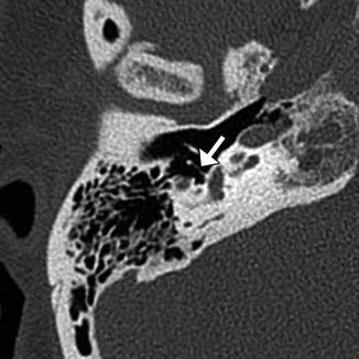
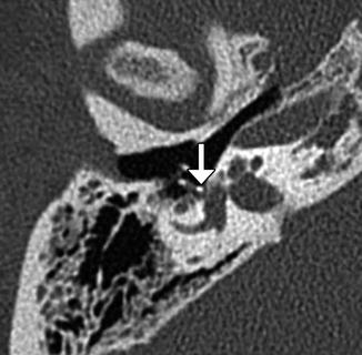
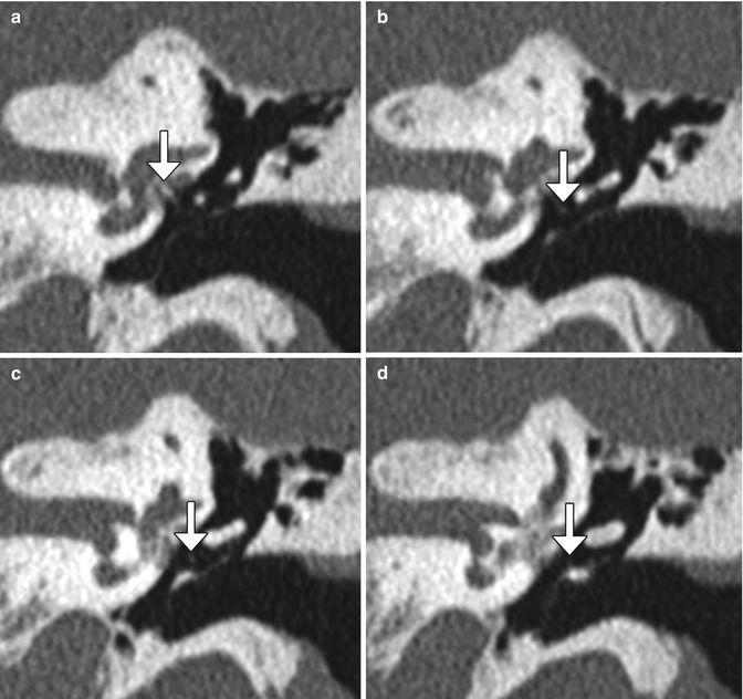
Fig. 8.31
Schematic of a stapes piston prosthesis (a). Photographs of piston and bucket handle stapes prostheses (b) (Courtesy of Grace Medical)
Fig. 8.32
Robinson bucket handle prosthesis. Coronal CT image shows a metallic prosthesis that extends from the long process of the incus to the oval window, where there is beam-hardening artifact
Fig. 8.33
Schuknecht Teflon wire stapes piston prosthesis. Axial CT image shows the filamentous prosthesis in position (arrow)
Fig. 8.34
Smart nitinol wire piston prosthesis. Axial CT image shows the prosthesis in position (arrow) in contact with the stapes footplate
Fig. 8.35
Stapedectomy with malleus grip prosthesis. Serial coronal CT images (a–d) demonstrate a wire prosthesis (arrows) extending from the stapes footplate to the malleus
Fig. 8.36
Susceptibility artifact from stapes prosthesis mimicking labyrinthitis ossificans. Axial CT image (a) shows a large metallic Robinson prosthesis. The corresponding axial CISS image (b) shows obscuration of a portion of the cochlea due to the artifact (encircled)
8.11 Ossicular Prosthesis Complications
8.11.1 Discussion
CT imaging may be obtained after ossicular chain reconstruction if a poorer-than-expected hearing outcome results in order to determine if the prosthesis has slipped or if there is another potential cause of hearing loss such as middle ear effusion, fixation of prosthesis or ossicular remnant by scar tympanosclerosis (especially involving the malleus or incus head in the epitympanum), or recurrent cholesteatoma. Encasement of a prosthesis by granulation tissue or cholesteatoma can cause conductive hearing loss whether or not the ossicular prosthesis is displaced.
Complications of ossicular prostheses depend on the particular type of prosthesis, but generally include migration into the vestibule (TORP or stapes prosthesis) (Fig. 8.37), perilymphatic fistula (Fig. 8.38), subluxation, dislocation, extrusion or other form of malposition (Figs. 8.39, 8.40, 8.41, 8.42, 8.43, 8.44, 8.45, and 8.46), encasement/displacement by granulation tissue or recurrent cholesteatoma (Figs. 8.47 and 8.48), tympanic membrane dehiscence (Fig. 8.49), and bending or fracture of the prostheses (Fig. 8.50). Prosthesis subluxation or dislocation is the most common complication responsible for up to 60% of postoperative hearing loss and occurs most commonly in the first 6–8 weeks before fibrosis occurs. Stapes prostheses most commonly displace posterior and inferior to the oval window. Alternatively, these prostheses can migrate into the vestibule, which can cause vertigo and possibly a concurrent perilymphatic fistula. Vestibular penetration is a serious complication that represents 10% of stapes prosthesis complications. Signs of perilymphatic fistula include the presence of air in the labyrinth (pneumolabyrinth) and rarely middle ear effusion. The portion of the prosthesis at the stapes footplate can reliably penetrate the vestibule without causing symptoms is 0.25 mm, but slightly deeper penetration may be asymptomatic in some cases. Prosthesis extrusion through the tympanic membrane occurs in 2.6–7% of cases depending on the type of prosthesis and method of tympanoplasty. The main risk factor for prosthesis extrusion is ongoing Eustachian tube dysfunction. CT is the modality of choice for evaluating most of these complications, especially in the late postoperative period. However, MRI is generally better for characterizing granulation tissue and cholesteatoma.
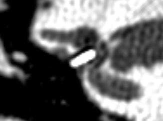
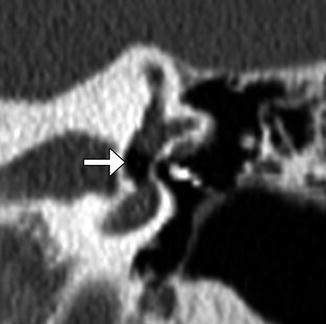
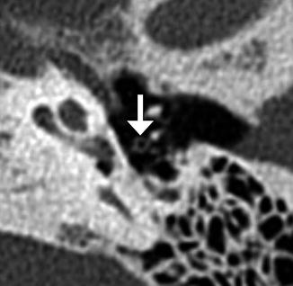
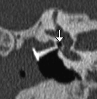
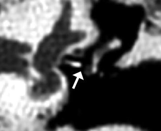

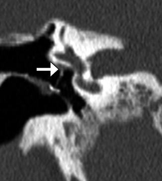
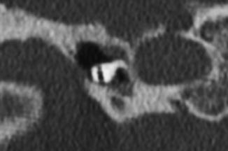
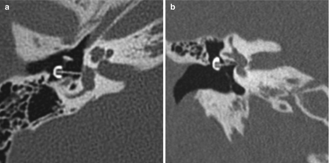
Fig. 8.37
Vestibular perforation. Coronal CT image shows medial displacement of the stapes prosthesis into the vestibule through the oval window
Fig. 8.38
Perilymphatic fistula. The patient presented with acute vertigo after stapedectomy. Coronal CT image shows air within the vestibule (arrow) and a laterally displaced stapes prosthesis
Fig. 8.39
Stapes prosthesis separation from the incus. Axial CT image shows an empty prosthesis wire loop (arrow) adjacent to the incus (Courtesy of Mary Elizabeth Cunnane, M.D.)
Fig. 8.40
Lateralized TORP. Coronal CT image shows an air gap (arrow) between the shaft of the hydroxyapatite prosthesis and the oval window. There is also extensive nonspecific opacification of the widened external auditory canal
Fig. 8.41
Stapes prosthesis detachment from the incus. Coronal CT image shows an air gap (arrow) between the lenticular process of the incus and McGee stapes prosthesis
Fig. 8.42
Stapes bucket prosthesis dislocation. Axial CT image shows the distal end of the prosthesis (arrow) projecting far anterior to the region of the oval widow
Fig. 8.43
TORP facial nerve impingement. Coronal CT image shows the medial ends of the prosthesis contacting the tympanic segment of the facial nerve canal (arrow)
Fig. 8.44
Dislocated PORP. Coronal CT image shows the Wehr’s short single-notch incus prosthesis in the hypotympanum, adjacent to the Eustachian tube orifice
Fig. 8.45
PORP detachment from stapes. Coronal (a) and axial (b) CT images show the shaft of the prosthesis separated and angled away from the oval window, far removed from the stapes (arrow)
Fig. 8.46
Extruded TORP. Axial (a) and coronal (b) CT images show the black oval-top prosthesis head that extends lateral to the tympanic membrane, while the shaft still contacts the footplate
Fig. 8.47
 Imaging of the Postoperative Skull Base and Cerebellopontine Angle
 Imaging of Cerebrospinal Fluid Shunts, Drains, and Diversion Techniques
 Imaging the Paranasal Sinuses and Nasal Cavity
 Imaging the Postoperative Scalp and Cranium
 Imaging of Vascular and Endovascular Surgery
 Imaging of Postoperative Spine


Dislocated TORP encased in soft tissue. Poschl plane CT image shows a hydroxyapatite TORP orientated upside down and encased by nonspecific soft tissue
Related posts:
Imaging of the Postoperative Skull Base and Cerebellopontine Angle
Imaging of Cerebrospinal Fluid Shunts, Drains, and Diversion Techniques
Imaging the Paranasal Sinuses and Nasal Cavity
Imaging the Postoperative Scalp and Cranium
Imaging of Vascular and Endovascular Surgery
Imaging of Postoperative Spine
Stay updated, free articles. Join our Telegram channel
Full access? Get Clinical Tree
