Fig. 6.1
External ventricular drain. Coronal CT image (a) shows the catheter within the right lateral ventricle and the external portion (arrow). Photograph of an external ventricular drain (b) (Courtesy of Marc Moisi)
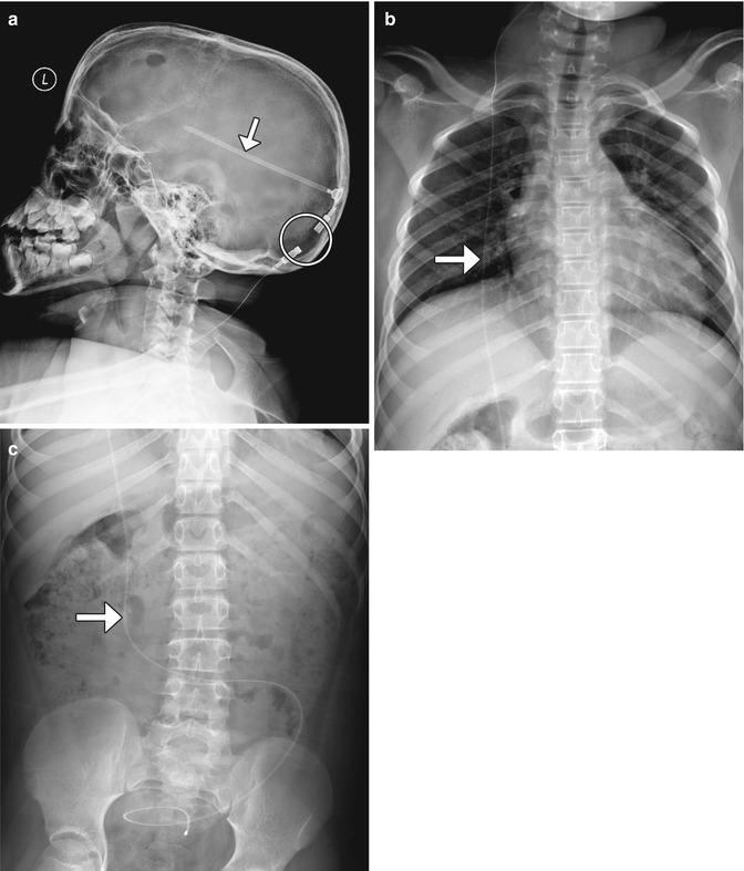
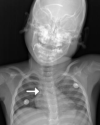
Fig. 6.2
Shunt series. Selected radiographs (a–c) show the proximal portion of the shunt catheter overlies the lateral ventricle (arrow); exits through a burr hole; tunnels into the subcutaneous tissues of the head, neck, chest, and abdomen (arrow); and terminates within the peritoneal cavity (arrow). Radiolucent portions (encircled) of the shunt should not be mistaken for discontinuities
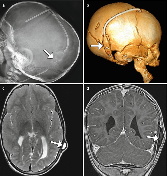
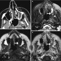
Fig. 6.3
Delta 1.5 valve VP shunt. Lateral skull radiograph (a) and 3D CT (b) images demonstrate the reservoir component (arrows) of the VP shunt containing performance level markers. Axial T2-weighted (c) and coronal post-contrast T1-weighted (d) MR sequences show the cerebrospinal fluid-filled reservoir (arrows) positioned in the subgaleal space
Programmable valves contain radiopaque chiral markers that enable the valve opening pressure setting or performance level to be determined radiographically (Figs. 6.4, 6.5, 6.6, and 6.7). Some models have devices that allow these settings to be determined without radiographs. Antisiphon devices are also incorporated into some models in order to prevent cerebrospinal fluid overdrainage, when the patient is upright. While programmable shunts are generally MRI compatible up to 3T, there is a potential risk for inadvertent change of settings during MRI scanning. Thus, it is imperative to verify the settings following MRI. The pressure settings can be adjusted noninvasively using a magnetic tool. Furthermore, recent innovations have made available programmable valves that are resistant to environmental magnetic influences.
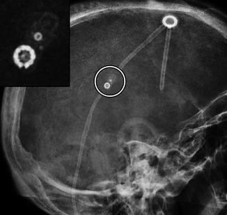

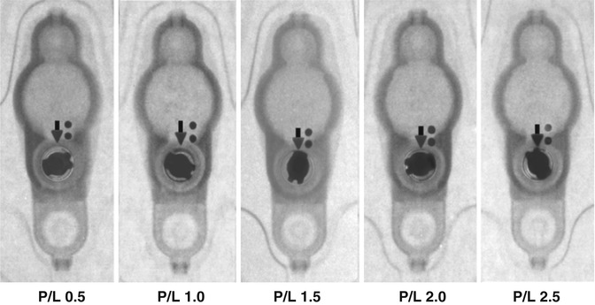
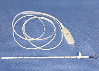
Fig. 6.4
Codman Hakim programmable shunt valve. Lateral radiograph with magnified view (inset) shows the components of the device (encircled) with pressure setting markers
Fig. 6.5
Strata valve programmable shunt. Lateral radiograph (a) with magnified view (inset) of the VP shunt valve (encircled). The pressure setting can be read on the radiograph, but not on the axial CT image (b). The magnetic components of the programmable shunt produce extensive susceptibility artifacts on MRI (c)
Fig. 6.6
Valve performance level setting chart (Courtesy of Medtronic)
Fig. 6.7
Photograph of ventriculoperitoneal shunt components (Courtesy of Patricia Smith and Sarah Paengatelli)
Gliosis often forms around the ventricular shunt catheter tract, but generally does not have clinical significance. The gliosis typically appears as circumferential low attenuation on CT and high signal on T2-weighted MRI measuring up to several millimeters in thickness (Fig. 6.8).
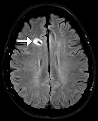
Fig. 6.8
Catheter-associated gliosis. Axial FLAIR MRI shows circumferential high signal surrounding the shunt catheter tract (arrow)
Up to one-third of VP shunts fail within 1 year of placement, and shunt revision is necessary in up to 70–80% of patients during their lifetime. Overall, programmable VP shunts have a similar failure rate as standard shunts. However, the pressure adjustment capability of programmable VP shunts leads to patient improvement in over 50% of cases. Complications include the following, for which examples are depicted later in this chapter:
Infection (most common: 5–47%)
Obstruction (usually proximal: emergency condition due to resulting increased ICP)
Subcutaneous cerebrospinal fluid collections
Catheter disconnection/migration/retraction (anywhere from mouth to anus!)
Incisional hernia
Bowel obstruction/volvulus
Viscus perforation
Cerebrospinal fluid pseudocysts
Conduit for metastatic spread
Imaging plays an important role in evaluating patients with VP shunts. Radiographic shunt series are commonly performed as an initial screening for suspected shunt failure. However, these studies are less sensitive than cross-sectional imaging modalities. Nuclear medicine shunt studies are uncommonly performed but can be used to assess for shunt patency. Radiotracer, usually Tc-99m DTPA or In-111 DTPA, is injected into to the reservoir (Fig. 6.9). Normally, the radiotracer material spills freely throughout the peritoneal cavity. A focal collection of radiotracer suggests the presence of a pseudocyst. Reflux may normally occur into the ventricles and the reservoir emptying half-time of less than 10 min, although this may vary depending on the type of shunt. A similar concept for evaluating shunt patency is the “shuntogram,” which involves injection of contrast material into the shunt valve, and tracking the flow of the contrast via serial radiographs of the cranial, chest, and abdominal components of the shunt system is obtained over the course of approximately 15 min.
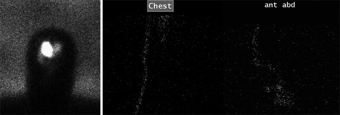
Fig. 6.9
Patent shunt catheter depicted on a nuclear medicine shunt study. Sequential 99mTc DTPA shunt images obtained over a 30-min period after injection of radiotracer into the ventricles via a shunt catheter show unimpeded passage of radiotracer from the ventricular system into the peritoneal cavity
6.1.3 Atypical Ventricular Shunts
6.1.3.1 Discussion
Other parts of the body can be used as terminals for the distal portions of ventricular shunt catheters. Ventriculoatrial, ventriculopleural, ventriculovesical, and ventriculo-gallbladder shunts are plausible alternatives for diverting cerebrospinal fluid away from the ventricles in patients with hydrocephalus, particularly when ventriculoperitoneal shunts fail.
Ventriculoatrial Shunts (Fig. 6.10): The distal tip of a ventriculoatrial shunt should terminate in the right atrium or even in the superior vena cava. Complications particular to ventriculoatrial shunts include pulmonary embolism and endocarditis.
Ventriculopleural Shunts (Fig. 6.11): The terminus is within the pleural space. Variable amounts of cerebrospinal fluid may accumulate in the pleural space, in which up to 20% are symptomatic. This complication is more prevalent in infants due to the smaller surface area for fluid resorption.
Ventriculoureteral Shunts: The terminus of the shunt is located in the ureter through a Roux-en-Y anastomosis. Diversion of cerebrospinal fluid can result in electrolyte abnormalities and cystitis.
Ventriculocholecystic Shunts: Shunt tip terminations in the gallbladder have a satisfactory long-term success rate of over 60%. The most common complications include obstruction and cholecystitis, with an incidence of about 10% each.
Fig. 6.10
Ventriculoatrial shunt. Frontal radiograph shows a ventricular shunt tip (arrow) at the level of the atriocaval junction (arrow)
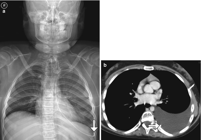
Fig. 6.11
Ventriculopleural shunt. Frontal radiograph (a) and axial CT (b) show a shunt catheter with distal end (arrows) located within the left pleural space, where there is cerebrospinal fluid
6.1.4 Ventriculosubgaleal Shunts
6.1.4.1 Discussion
Ventriculosubgaleal shunting is diversion of intraventricular cerebrospinal fluid into the subgaleal space for temporary absorption by the subcutaneous tissues of the scalp. These shunts are a relatively straightforward, effective, and safe option for temporary treatment of hydrocephalus. Ventriculosubgaleal shunting can avoid the need for external drainage or frequent cerebrospinal fluid aspiration in unstable neonates until the cerebrospinal fluid characteristics and abdomen are suitable for ventriculoperitoneal shunting. On CT and MRI, the ventriculosubgaleal shunt catheter can be traced from the ventricular system to the subgaleal space, where there is often a variable amount of cerebrospinal fluid accumulation (Fig. 6.12).

Fig. 6.12
Ventriculosubgaleal shunt. Sagittal T2-weighted MRI in a neonate show a pocket of subgaleal cerebrospinal fluid surrounding the ventriculosubgaleal shunt reservoir (Courtesy of Tina Young Poussaint MD)
6.1.5 Ventriculo-cisternal (Torkildsen) Shunts
6.1.5.1 Discussion
The Torkildsen shunt was initially conceived to bypass aqueductal stenosis and allow cerebrospinal fluid to drain directly through an extracranial pathway from the lateral ventricle to the cervical subarachnoid space. While this technique has been replaced by endoscopic third ventriculocisternostomy, the Torkildsen shunt approach is occasionally necessary in cases of complex hydrocephalus. The Torkildsen shunt typically courses from a lateral ventricle to the cisterna magna at the level of the foramen magnum (Fig. 6.13). These shunts are introduced into the lateral ventricle via a parieto-occipital burr hole and then exit to the extracranial space via that burr hole to course into the foramen magnum where the shunting tube is introduced into the cervical subarachnoid space. Occasionally, a C1 laminectomy is required for this procedure. The proximity of the distal end of the shunt to the cervicomedullary junction can predispose to upper spinal cord compression, rarely resulting in cervical myelopathy. Imaging can be used to evaluate such symptoms.
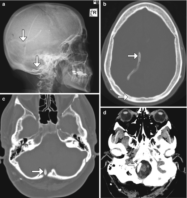
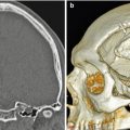
Fig. 6.13
Ventriculo-cisternal shunt. The patient has a history of chronic headaches and multiple shunts, including a Torkildsen shunt that was placed many years before. Lateral radiograph (a) and axial CT images (b–d) demonstrate the course of the internal shunt catheter (arrows) from the right lateral ventricle, inferiorly behind the cerebral hemisphere and cerebellum, and terminating at the level of the foramen magnum. There is a right occipital burr hole, through which the catheter was introduced
6.1.6 Percutaneously Accessed Cerebrospinal Fluid Reservoirs
6.1.6.1 Discussion
The subcutaneous cerebrospinal fluid devices consist of reservoirs positioned over the calvarium in the subgaleal space and catheters inserted into the intracranial compartment. The catheters can be inserted into the ventricular system or tumor cyst for decompression and connected to the reservoirs (Fig. 6.14). The reservoir can be accessed percutaneously using a needle. Ventricular reservoirs can also be converted into ventriculosubgaleal shunts or ventriculoperitoneal shunts, as many of these also have side ports. Complications of ventricular reservoirs include skin erosion and intracranial migration, which may require endoscopic retrieval, as well as generic complications encountered with all shunting systems.

Fig. 6.14
Percutaneous cerebrospinal fluid reservoir with catheter in ventricular system. Scout images in two different patients (a, b) show the reservoirs (encircled) in the scalp connected to ventricular catheters
6.1.7 Subdural-Peritoneal Shunts
6.1.7.1 Discussion
Subdural-peritoneal shunting devices can be used to treat chronic subdural hematomas that are sufficiently degraded to a fluid state, such that the collection can flow into the peritoneal space (Fig. 6.15). Compared with burr hole decompression and drainage alone, subdural-peritoneal shunts result in a lower recurrence rate. Complications include acute subdural hematoma, subdural empyema, and cerebral edema.
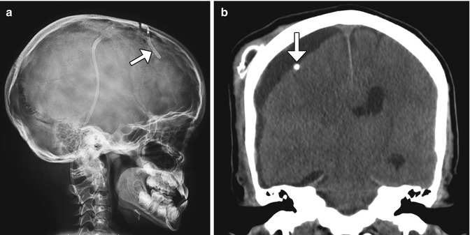
Fig. 6.15
Subdural-peritoneal shunt for chronic hematoma. Lateral radiograph (a) shows that the catheter tip lies just beneath the calvarium, in the subdural space(arrow). The rest of the catheter is tunneled in the subcutaneous tissues and runs toward the abdomen. The corresponding coronal CT image (b) shows the catheter tip (arrow) located within the right frontal convexity fluid collection
6.1.8 Cystoperitoneal and Cystoventriculostomy Shunts
6.1.8.1 Discussion
In rare instances, arachnoid cysts can cause symptoms and require surgical intervention. In some reports, cystoperitoneal (subarachnoid-peritoneal) shunting has proven effective for decompression of arachnoid cysts into the peritoneal cavity (Fig. 6.16). Meningoceles and cystic schwannomas are also sometimes amenable to cystoperitoneal shunting. Internal drainage of arachnoid cysts into regional ventricles or cisterns via stereotactic cystoventriculostomy is another feasible treatment approach, in which a drain is inserted in the cyst lumen and directed into an adjacent ventricle or cistern (Fig. 6.17).
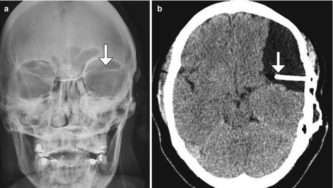
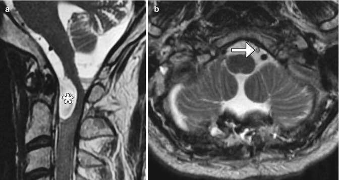
Fig. 6.16
Cystoperitoneal shunting. The patient has a history of ventriculoperitoneal shunt placement for arachnoid cyst and presents with headache. Frontal radiograph (a) shows that the tip of the shunt catheter (arrow) projects over the left hemisphere, not in the expected location of the ventricular system. Axial CT image (b) shows a cystoperitoneal shunt catheter (arrow) within a large left frontotemporal convexity arachnoid cyst
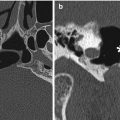
Fig. 6.17
Cystocisternal shunt. The patient has a history of arachnoid cyst secondary to Candida meningitis with obstruction of cerebrospinal fluid at the level of craniocervical junction, resulting in cord compression. Preoperative sagittal T2-weighted image (a) shows a cerebrospinal fluid intensity collection at the craniocervical junction, which exerts mass effect upon the spinal cord and medulla (*). Postoperative axial (b) T2-weighted MRI demonstrates a drainage catheter (arrow) within the subarachnoid space anterior to the cervicomedullary junction
6.1.9 Syringosubarachnoid and Syringopleural Shunts
6.1.9.1 Discussion
Direct intervention for syringohydromyelia is generally considered a rescue procedure and can be accomplished via syringosubarachnoid or syringopleural shunting. Syringosubarachnoid shunting can be used to treat syringohydromyelia related to a variety of causes, such as tumor, trauma, and Chiari malformations. This procedure serves to free the obstructed cerebrospinal fluid pathways via myelotomy and insertion of a Silastic T-shaped tube. The tube extends from the syringohydromyelia cavity to the subarachnoid space, into which the excess cerebrospinal fluid drains (Fig. 6.18). The T-shaped configuration of the tube allows cerebrospinal fluid to drain from both superior and inferior directions in the syrinx.
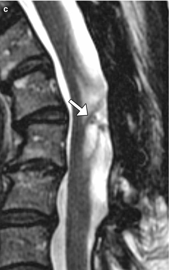
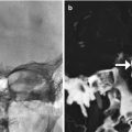
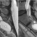
Fig. 6.18
Syringosubarachnoid shunt. Two patients’ status post T-tube insertion for cervical spine syringomyelia decompression. Sagittal (a) CT image in one patient shows the hyperattenuating portions of the T-tube. Sagittal preoperative T2-weighted MRI (b) in another patient shows a large syrinx (*) in the cervical spinal cord, which was successfully decompressed following T-tube insertion (arrow), as shown on the postoperative T2-weighted MRI (c). There is also new kyphotic deformity after multilevel laminectomy
Syringopleural shunts can also be used to treat syringomyelia by extending a catheter from the syrinx to the pleural cavity as a negative pressure terminus (Fig. 6.19).
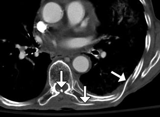
Fig. 6.19
Syringopleural shunt. Axial CT image shows a shunt catheter that extends from the spinal canal along the left back subcutaneous tissues into the pleural cavity (arrows)
6.1.10 Lumboperitoneal Shunts
6.1.10.1 Discussion
Lumboperitoneal shunting is an alternative method for treating pseudotumor cerebri and communicating hydrocephalus separate from ventriculoperitoneal shunting. The procedure consists of introducing an intrathecal catheter and tunneling a distal catheter through the abdominal subcutaneous tissues and into the peritoneal cavity (Fig. 6.20). Lumboperitoneal shunt catheters can incorporate percutaneous programmable or gravity-actuated antisiphon components, in order to regulate pressure and reduce the risk of overdrainage (Figs. 6.21 and 6.22). Reported complications include malfunction, malposition, hemorrhage, and infection.
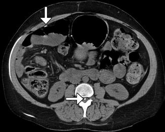
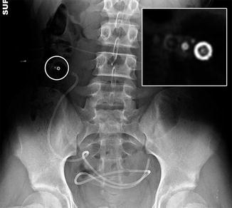
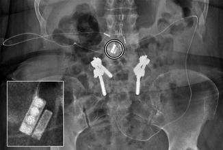
Fig. 6.20
Lumboperitoneal shunt. The patient has a history of pseudotumor cerebri and cerebrospinal fluid rhinorrhea. Axial CT image shows the shunt catheter (arrows) extending from the spinal canal, through the subcutaneous tunnel, and into the peritoneum
Fig. 6.21
Lumboperitoneal shunt catheter with percutaneously programmable valve. Frontal radiograph shows the lumboperitoneal shunt catheter in position with a programmable valve component (encircled), which is magnified in the inset
Fig. 6.22
Lumboperitoneal shunt catheter with gravity-actuated horizontal-vertical (HV) valve system. Frontal radiograph shows the lumboperitoneal shunt catheter in position with gravity-actuated valve component (encircled), which is magnified in the inset
6.1.11 Third Ventriculocisternostomy
6.1.11.1 Discussion
Endoscopic fenestration of the anterior floor of the third ventricle (Liliequist’s membrane) creates an alternative route for cerebrospinal fluid into the subarachnoid space via the prepontine cistern. This procedure bypasses obstruction at the level of the Sylvian aqueduct and restores cerebrospinal fluid flow out of the ventricular system. Third ventriculocisternostomy is a minimally invasive alternative to shunt implantation and is indicated for patients with aqueductal stenosis, obstructive tumors, and obstructive cysts.
The hemodynamic changes induced by third ventriculocisternostomy can be detected on MRI (Fig. 6.23). In particular, the sagittal phase-contrast cine sequence is the gold standard for evaluating cerebrospinal fluid flow dynamics. Following successful third ventriculostomy, a flame-shaped jet of high signal (flow) intensity across the floor of the third ventricle is characteristic. A jet of cerebrospinal fluid can also manifest on T2-weighted sequences. With high-resolution heavily T2-weighted cisternogram-type sequences, the normal Liliequist’s membrane can be identified. Following third ventriculostomy, the membrane will appear disrupted.
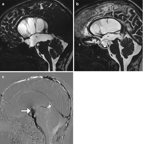
Fig. 6.23
Third ventriculocisternostomy. Preoperative sagittal FIESTA (a) shows enlargement of the third and lateral ventricles. Postoperative sagittal FIESTA (b) shows a defect in Liliequist’s membrane (encircled) and decrease in size of the third and lateral ventricles. The postoperative sagittal phase-contrast MRI(c) shows the a strong jet of cerebrospinal fluid (arrow) across the third ventriculostomy
6.1.12 Endoscopic Septum Pellucidum and Intraventricular Cyst Fenestration
6.1.12.1 Discussion
Endoscopic fenestration can be performed to treat symptomatic septum pellucidum cysts. The procedure consists of creating a burr hole, introducing a cannula and endoscope into the lateral ventricles, and coagulating the septum pellucidum to allow communication between the right and left lateral ventricles. Postoperative MRI can show the disrupted membranes of the septum pellucidum and decrease in size of the cyst after successful fenestration (Fig. 6.24). Arachnoid and porencephalic cysts can be successfully fenestrated to create a communication with the ventricular system or cisterns, averting the need for a shunt catheter. Rarely, tumor cysts are decompressed into the ventricular system as a last resort (Fig. 6.25). This approach is generally avoided due to the risk of subsequent hydrocephalus secondary to malabsorption from the cyst contents.
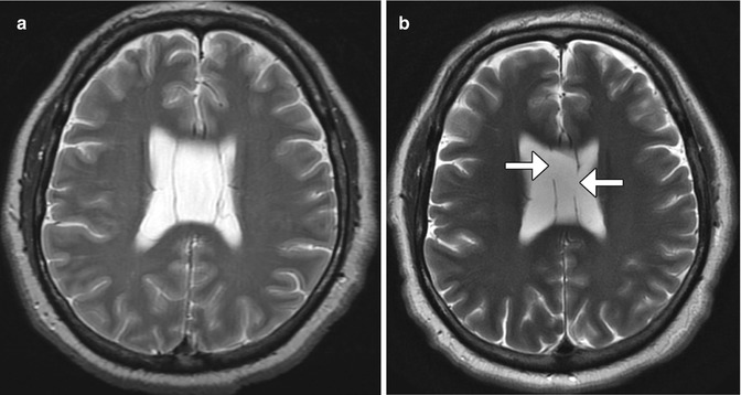
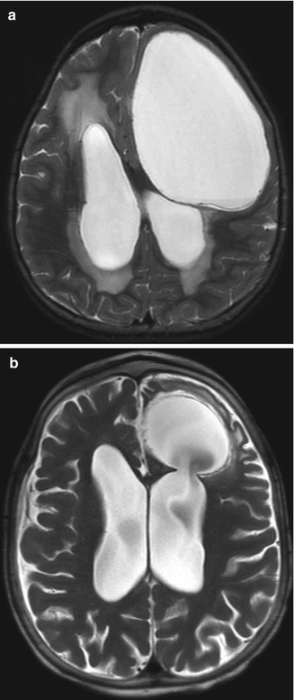
Fig. 6.24
Endoscopic septum pellucidum cyst fenestration. Preoperative T2-weighted MRI (a) shows a dilated cavum septum pellucidum cyst. Postoperative T2-weighted MRI (b) shows bilateral defects in the septum pellucidum (arrows) resulting in decompression of the cyst
Fig. 6.25
Endoscopic cyst fenestration into the ventricular system. Preoperative axial T2-weighted MRI (a) shows a large cystic lesion that compresses the left frontal lobe and abuts the left lateral ventricle. Postoperative axial T2-weighted MRI (b) shows interval decrease in size of the cystic lesion, which now communicates with the left lateral ventricle through a surgical defect
6.1.13 Aqueductoplasty
6.1.13.1 Discussion
Aqueductoplasty with or without stenting is a treatment option for isolated fourth ventricle resulting from membranous aqueductal stenosis. Balloon dilatation can be performed to expand the obstructed aqueduct of Sylvius (Fig. 6.26). Alternatively, a small-caliber flexible endoscope can be used to create a perforation in the offending membrane and to introduce a stent. Following aqueductoplasty, the third and lateral ventricles usually decrease in size. If inserted, the aqueductal stent is visible as a radioattenuating tubular structure on CT that extends from the fourth ventricle to the floor of the third ventricle and should not be misconstrued as a migrated shunt fragment in the appropriate setting.
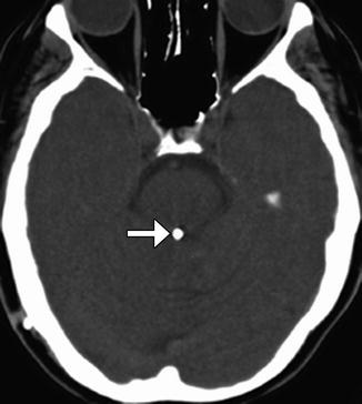
Fig. 6.26
Aqueductoplasty and stenting. Axial CT image shows a stent within the aqueduct of Sylvius (arrow)
6.1.14 Endoscopic Choroid Plexus Cauterization
6.1.14.1 Discussion
Choroid plexus surgery is an option for treating hydrocephalus in patients with suspected cerebrospinal fluid overproduction and patients lacking a septum pellucidum. Choroid plexus cauterization can be performed endoscopically and consists of coagulating a portion of the choroid plexus. On imaging, truncation of the treated choroid plexus can be appreciated (Fig. 6.27). Interestingly, following choroid plexus cauterization alone, ventricular size does not necessarily decrease significantly, although sulci become more prominent indicating decreased cerebrospinal fluid pressure. Nevertheless, choroid plexus cauterization is often performed in conjunction with ventriculocisternostomy.
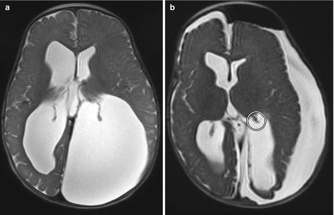
Fig. 6.27
Choroid plexus cauterization. Preoperative axial T2-weighted MRI (a) shows dilatation of the lateral ventricles, particularly the atrium of the left lateral ventricle, resulting in cranial vault deformity. Postoperative axial T2-weighted MRI (b) shows interval truncation of the left lateral ventricle choroid plexus secondary to fulguration (encircled). Sequelae of left ventricular fenestration are also demonstrated, with resultant decompression of the ventricular system and development of extra-axial cerebrospinal fluid
Choroid plexus papillomas can cause hydrocephalus due to overproduction of cerebrospinal fluid with rates of over 1.0 mL/min as well as subarachnoid obstruction. Total surgical resection of the tumor and vascular pedicle is the treatment of choice. Coagulation of the tumor can facilitate resection. After resection, the hydrocephalus usually resolves (Fig. 6.28). Additional treatment for hydrocephalus after resection may be required due to intraventricular hemorrhage, inflammation from surgery, and mechanical distortion of the ventricular system.
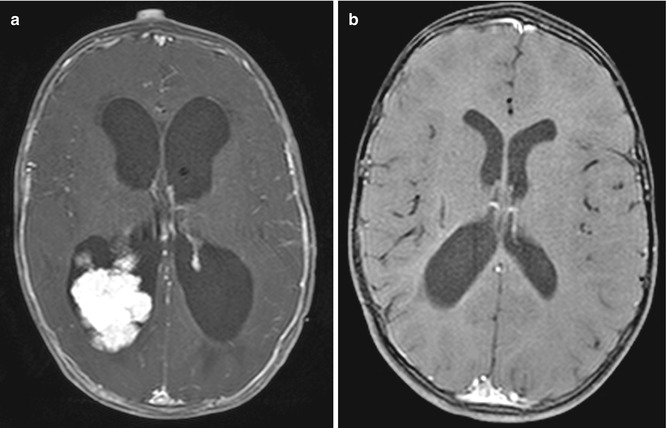
Fig. 6.28
Choroid plexus tumor resection. Preoperative axial post-contrast T1-weighted MRI (a) shows a lobulated mass within the right lateral ventricle and marked enlargement of the ventricular system. Postoperative post-contrast T1-weighted MRI (b) shows interval resection of the tumor and markedly decreased ventricular size
6.2 Complications Related to Cerebrospinal Fluid Diversion Surgeries
6.2.1 Corpus Callosum Changes Secondary to Shunt Catheterization
6.2.1.1 Discussion
Due to its proximity to lateral ventricle shunt trajectories, the corpus callosum is prone to injury during catheter insertion. This can result in linear areas of high T2 signal in the corpus callosum adjacent to the catheter. Corpus callosal swelling can also occur after ventricular shunting for long-standing obstructive hydrocephalus. This appears as enlargement and hypoattenuation on CT images corresponding to increased T2 and decreased T1 signal on MRI that are often oriented transversely with a striated pattern, mainly within the body of the corpus callosum (Fig. 6.29). The etiology for the signal changes is likely attributable to compression of the corpus callosum against the rigid falx cerebri from hydrocephalus prior to shunting. These changes are typically not associated with symptoms and should not be misinterpreted as neoplasm, white matter disease, or leukoencephalopathy in particular, the corpus callosum can acquire a scalloping deformity, which is best appreciated on sagittal images. Furthermore, the changes often resolve over time.
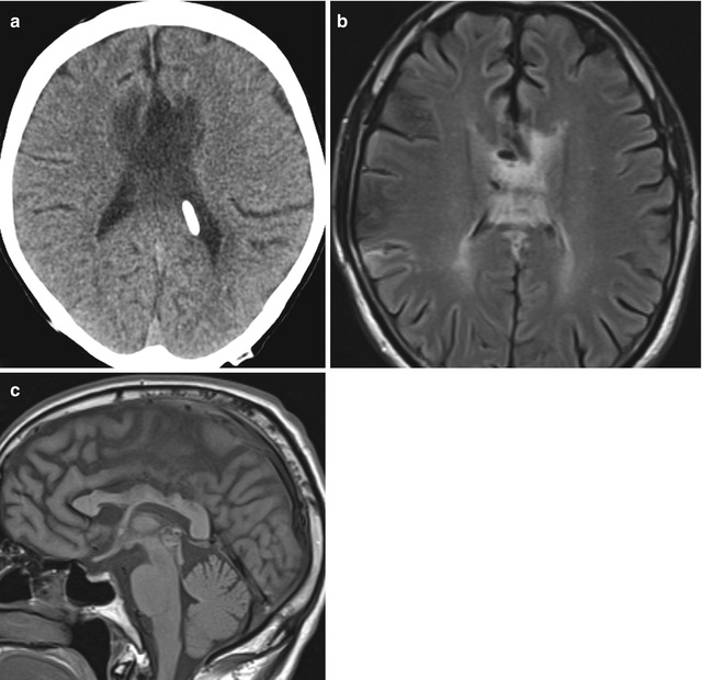
Fig. 6.29
Corpus callosal swelling. Axial CT image (a) shows low attenuation and enlargement of the body of the corpus callosum. Axial T2-weighted MRI (b) shows striated high signal in the corpus callosum. Sagittal T1-weighted MRI (c) shows scalloping deformity of the corpus callosum
6.2.2 Shunt-Associated Intracranial Hemorrhage
6.2.2.1 Discussion
Intraparenchymal, subdural, and intraventricular hemorrhage associated with placement of VP shunts is an uncommon complication, with an estimated incidence of 0.3–4% (Fig. 6.30). Intracranial hemorrhage may present soon after ventricular catheterization or it can be delayed. Predisposing factors include underlying parenchymal friability, venous occlusion, coagulopathy, multiple catheter passes, choroid plexus injury, and malpositioning near a vascular structure. Intraparenchymal hemorrhage associated with VP shunting typically runs parallel to the length of the tubing and can be circumferential. Frequently, choroid plexus hemorrhage can lead to disseminated intraventricular hemorrhage and can contribute to shunt malfunction.
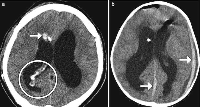
Fig. 6.30
Shunt-associated hemorrhage. Axial CT image (a) obtained 2 days following VP shunt placement shows a focus of right frontal lobe hemorrhage adjacent to the catheter (arrow). There is also hemorrhage within the choroid plexus and the posterior horn of the right lateral ventricle (encircled). Axial CT image in a different patient (b) shows subdural hematomas (arrows) that formed shortly after shunt catheter insertion.
The development of chronic calcified subdural hematomas is a potential long-term complication of ventriculoperitoneal shunting. The calcifications tend to occur at the margins of the fluid collection (Fig. 6.31), but may sometimes be more confluent. When bilateral, these have been termed “armored brain.” Although the calcified subdural hematomas can produce symptoms, they generally do not require further intervention.
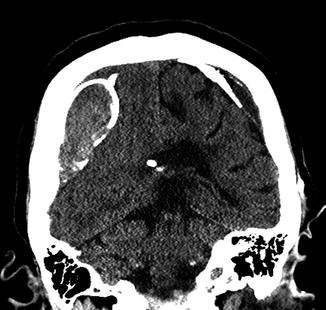
Fig. 6.31
Chronic calcified subdural hematoma. Coronal CT image shows peripherally calcified bilateral cerebral convexity subdural collections in a patient with long-standing ventricular shunting
6.2.3 Intraventricular Fat Migration
6.2.3.1 Discussion
Fragments of subcutaneous adipose tissue can uncommonly migrate into the intracranial cisterns and ventricular system either during placement of a cerebrospinal fluid shunt catheter, since the catheter is tunneled through subcutaneous fat. This complication is apparent on MRI and CT as nodules with fat characteristics within the ventricles or cisterns (Fig. 6.32) can be adherent to the ventricular walls. Nevertheless, patients are often not symptomatic from this.

Fig. 6.32
Intraventricular fat. The patient underwent recent lumboperitoneal shunt insertion. Coronal CT image shows fat-attenuation material within the suprasellar cistern and right Sylvian fissure (arrows)
6.2.4 MRI-Induced Programmable Valve Setting Alteration
6.2.4.1 Discussion
Recurrent hydrocephalus in patients with indwelling ventricular shunts is a sign of shunt failure. Of note, high-field-strength MRI can alter the pressure setting of most percutaneous programmable cerebrospinal fluid shunts and may also result in acute hydrocephalus, mimicking shunt malfunction, if the setting is not checked and reset after the scan (Fig. 6.33). The accumulation of cerebrospinal fluid can lead to ventricular enlargement, unless there is extensive preexisting ventricular scarring that limits ventricular expansion. Enlargement of the temporal horns is among the earliest findings of this complication. Other signs include effacement of the sulci and transependymal flow of cerebrospinal fluid. Hydrocephalus can result in sutural diastasis and enlargement of cranial diameter in children.
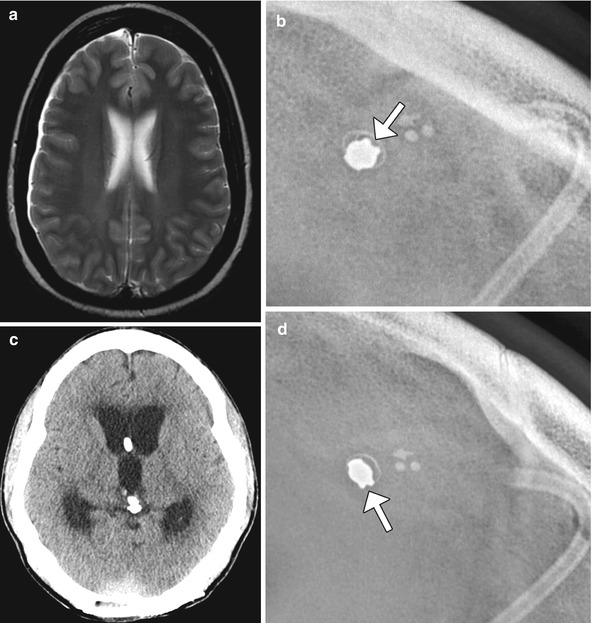
Fig. 6.33
MRI-induced programmable valve setting alteration. The patient with a percutaneously programmable cerebrospinal fluid shunt, presented acutely obtunded after undergoing MRI at 1.5T the previous day. The pressure settings were not checked following MRI. The following day, the patient was minimally responsive and was noted that the pressure setting changed from 0.5 to 2.5 on the Medtronic Strata valve. This change was presumably secondary to the magnetic field. Axial T2-weighted MRI (a) shows no ventricular dilatation. Shunt survey (b) obtained before the MRI shows a pressure setting of 0.5. Axial CT image (c) obtained the day after the MRI shows acute massive hydrocephalus and the subsequent shunt survey (d) shows a pressure setting of 2.5
6.2.5 Ventricular Loculations and Isolated Ventricles
6.2.5.1 Discussion
The formation of loculations of cerebrospinal fluid within the ventricular system can lead to shunt failure. The compartmentalized collection of cerebrospinal fluid can lead to symptoms of hydrocephalus and may be caused by adhesions from prior hemorrhage or infection, for example. CT ventriculography performed by injecting contrast into the shunt catheter can be used to delineate the presence of loculations by the lack of communication of the contrast material with the rest of the ventricular system (Fig. 6.34). Similarly, an isolated or trapped ventricle is an uncommon phenomenon that can occur in the setting of ventricular shunting with adhesion formation and represents a form of focal hydrocephalus. The significance of this complication is that it can exert mass effect upon surrounding structures. On imaging, disparate sizes of the ventricles are apparent, and contrast does not enter the trapped ventricle on CT ventriculography if the contrast is injected into the other portions of the ventricular system (Fig. 6.35). The level of obstruction is often at the foramen of Monro, but can occur anywhere in the ventricular system. Treatment may consist of ventricular catheter repositioning, septostomy, foramen of Monro reconstruction, or implantation of a catheter into the affected ventricle. Isolated ventricles that are not enlarging can be difficult to differentiate from asymmetric ventricles, which may also be encountered after shunting and do not require treatment. Midline shift and progressive increase in size of the ventricle suggest trapping over simple asymmetry of the ventricles. If there is any doubt, short interval imaging follow-up can be performed.