Imaging the Cervical, Thoracic, and Lumbar Spine


In this chapter, we discuss imaging of the cervical, thoracic, and lumbar spine. Although differences exist, many common themes are shared in both the selection and the interpretation of diagnostic studies for all regions of the spine. Our discussion of all spinal regions starts with interpretation of images, with a focus on computed tomography (CT) scan. We correlate CT findings with x-ray when possible, and we demonstrate associated soft-tissue abnormalities identified on magnetic resonance imaging (MRI). Don’t be daunted by the number of figures in this chapter—we explore injuries and nontraumatic spinal pathology in many imaging planes and in multiple modalities to maximize your three-dimensional understanding. The figure captions are designed to allow the figures to stand alone, so we spend relatively little time discussing specific fracture patterns in the text. The figures in the chapter span a range of important spinal pathology, moving from cephalad to caudad. The list in Table 3-1 can guide you to the relevant figure, where diagnostic features are discussed in detail.


TABLE 3-1

Imaging Findings and Related Figure Numbers


Content Figure Number
Three-dimensional CT reconstructions of the normal cervical spine 3-1 through 3-7
X-rays of the normal cervical spine


  • Lateral


  • AP


  • Odontoid


  • Swimmer’s view


  • Flexion–extension


Normal sagittal CT views 3-19 and 3-20
Normal coronal CT view 3-21
Normal axial view 3-22
Occipital condyle fractures 3-24 through 3-27
C1 burst (Jefferson) fractures 3-28 through 3-31
Atlantoaxial (C1-C2) rotary fixations 3-32 through 3-38
C1 posterior arch fracture 3-39
C2 dens fractures, type II 3-40 through 3-43
C2 dens fractures, type III 3-44 through 3-48
Hangman’s fractures of C2 3-49 through 3-57
Transverse process fractures 3-58 and 3-98
Cervical burst compression fractures 3-59 through 3-62
Teardrop flexion fractures 3-63 through 3-66
Jumped facets, bilateral and unilateral 3-67 through 3-75
Cervical facet fractures with spinal cord injury on MRI 3-76 and 3-77
Cervical lamina fractures 3-78 through 3-80
Acute cervical ligamentous injuries with x-ray, CT, and MRI findings 3-81 through 3-84
Three-column concept of spinal stability 3-85
T2 corner avulsion fractures (extension teardrop) 3-86 and 3-87
Thoracolumbar compression and burst fractures 3-88 through 3-101
Chance fractures 3-99 through 3-101
Thoracic spine metastatic disease with cord compression 3-102 through 3-104
Vertebral osteomyelitis and discitis 3-105 through 3-107
Spinal epidural abscesses 3-108 through 3-110, 3-115, and 3-116
Vertebral tuberculosis (Pott’s disease) 3-111 through 3-116
Degenerative joint disease and disc herniation 3-117 through 3-120
Cauda equina, normal and compression 3-119 and 3-120
Osteopetrosis 3-121 and 3-122
Ankylosing spondylitis 3-123 through 3-127
Spinal cord injuries on MRI 3-77 and 3-127
Penetrating spinal trauma 3-128 through 3-131
Motion artifact on MRI 3-132
Syrinx 3-133
Pseudosubluxation 3-134 and 3-135


In many ways, the more difficult task for the emergency physician is not the interpretation of the image but the decision to image the spine. We review two well-validated clinical decision rules (CDRs) that can identify patients at low risk of cervical spine injury who do not require any imaging. Similar decision instruments can identify patients who require thoracic and lumbar imaging.


Imaging of the spine has undergone a revolution with the advent of multidetector CT with multiplanar reconstructions. We review the evidence for use of CT and x-ray, comparing their sensitivity for detection of fractures. Remarkably, the latest version of the American College of Radiology (ACR) Appropriate Guidelines for Imaging of Suspected Spine Trauma (2009) advocates thin-section CT as the primary screening study for suspected cervical spine injury in adults, removing plain radiography (x-ray) from this position. The three-view radiograph that has been the long-standing screening test in the emergency department is now recommended by the ACR “only when CT is not readily available.” Radiography is described in this document as “not … a substitute for CT.” The ACR cites a lack of evidence for recommendations of CT or x-ray as the primary screening tool for suspected cervical spine injury in children. We discuss the radiation burden and cost of cervical CT. The new ACR recommendation for a CT-first strategy guarantees an increase in the radiation exposure resulting from any screening for cervical spine injury. Consequently, an even greater emphasis should be placed on applying reliable CDRs. Let’s begin our discussion with the cervical spine, followed by a parallel discussion of the thoracic and lumbar spine.


Epidemiology of Cervical Spine Injury


Cervical spine injuries occur in approximately 2% to 4% of blunt trauma cases, and diagnostic imaging plays a pivotal role in the evaluation of patients for these potentially life-threatening or seriously debilitating injuries. In addition, nontraumatic cervical spine pathology occasionally requires imaging in the emergency department. This evaluation differs from the evaluation in trauma, as fractures or other bony pathology may not be present. The incidence of cervical injuries is relatively independent of the setting—level I, II, and III trauma centers (the U.S. designation) all encounter cervical spine injuries with similar frequency, and emergency physicians must be intimately familiar with the imaging required to diagnose these dangerous injuries. In one study of 165 U.S. medical centers involving 111,219 patients, 4.3% of patients had injuries, at similar rates, in both academic and nonacademic centers, regardless of trauma center type (I through III). The National Emergency X-radiography Utilization Study group, which is discussed in more detail later in regard to its CDR, found similar rates of injury: 2.4% of 34,069 patients in 21 U.S. medical centers.


Imaging the Cervical Spine Following Trauma: Application and Interpretation of Imaging Modalities


Cervical spine imaging following trauma must perform a number of clinical functions. These include identification of fractures, ligamentous injuries, and injuries to neurologic structures, including the spinal cord and nerve roots. Diagnostic modalities for cervical spine imaging are plain film, CT scan, and MRI. We consider each of these in turn, with examples of the types of pathology detected or ruled out and the limitations of each technique. Although the ACR now recommends CT rather than x-ray as the primary screening tool in adults, plain x-ray is still widely used in children, and CT is not available in all settings. We review the interpretation of x-rays and CT, recognizing that some patients may not undergo both tests. At this time, MRI is more rarely interpreted by emergency physicians, and we thus review MRI interpretation in less detail.


Evaluating for Fracture or Dislocation with Plain X-ray


Plain films in a neutral anatomic position with the patient immobilized in a cervical collar have long been the standard test to evaluate for bony fractures and dislocations. Although plain x-rays are still widely used, CT has increasingly become the primary modality for evaluation of fracture due to its higher sensitivity. Nonetheless, plain x-rays continue to play an important role in screening for fractures. Because of their limited sensitivity, plain x-rays should not be used to “rule out fracture” in cases with a high pretest probability of cervical spine injury.


Plain x-rays of the cervical spine identify fractures by three major methods:


  • Direct visualization of fractures (discontinuity of the bony cortex)


  • Misalignment of bony structures, suggesting possible fracture or dislocation


  • Soft-tissue changes, suggesting underlying fracture


Plain x-rays do not directly identify abnormalities of soft tissues such as spinal ligaments, although gross misalignment of vertebral bodies almost always indicates concurrent ligamentous injury. Plain x-rays also do not directly identify spinal cord injuries, although x-ray abnormalities showing impingement upon the spinal canal imply cord impingement. Direct visualization of ligamentous and cord injuries requires MRI. CT scan is useful in delineating fractures and dislocations in greater detail. As described later, CT with multiplanar reconstructions can visualize some soft-tissue injuries and, when normal, indicates a low likelihood of unstable cervical spine injury.


Standard Plain X-ray, Three Views


Figures 3-1 through 3-7 demonstrate three-dimensional CT models of the cervical spine. Review these, as they will assist you in understanding cervical spine anatomy and the information to be gleaned from the two-dimensional projections obtained in plain x-ray. An adequate cervical spine plain x-ray series consists of three images: a lateral, an anterior – posterior (AP), and an open-mouth odontoid view ( Figure 3-8 ). It is extremely important that adequate x-rays are obtained to maximize the sensitivity of this technique.


Figure 3-1


Lateral and oblique three-dimensional views of the normal cervical spine.

This three-dimensional reconstruction of the cervical spine was generated from standard computed tomography axial images using 1.25-mm slice thickness. Images like this are not routinely reviewed by emergency physicians, but they provide a good starting point for our discussion of cervical spine imaging. A, A lateral view, showing the normal relationship of C1 through T1 vertebrae. Compare this with the lateral x-ray in Figures 3-8 and 3-9 . Note the overlap of the cervical facet joints, like shingles on a roof. B, An anterior oblique view, similar in perspective to an oblique x-ray view sometimes obtained to inspect for narrowing of the spinal foramen through which spinal nerves exit. C, A posterior oblique view. This has no routine x-ray equivalent but demonstrates the spinal lamina and posterior processes.


Figure 3-2


Anterior three-dimensional view of the normal cervical spine.

This three-dimensional reconstruction from axial cervical spine images shares the same perspective with an anterior–posterior x-ray or coronal computed tomography (CT) views. The C1 vertebrae is cropped from this image—we look at C1 in detail in Figure 3-3 . C7 and T1 are also not in this image—as we discuss later, these must be seen in an x-ray series to allow adequate evaluation of the cervical spine. Note how the facet joints are not horizontal but slope caudad from anterior to posterior. As a result, these joints are not fully seen in a single axial CT image, as you will see in future figures. Also note how the spacing of vertebral bodies is symmetrical.

The lower portion of this reconstruction shows artifacts from a nasogastric (NG) tube.


Figure 3-3


C1 and C2 view of the normal cervical spine.

This three-dimensional reconstruction from computed tomography (CT) axial images focuses on the occipital–cervical junction and the C1-2 (atlantoaxial) junction. Note how the occipital condyles articulate with the superior surface of C1. The tip of the dens is hidden from view behind the anterior arch of C1. Two-dimensional slices can be more useful in identifying injuries because superficial structures do not obscure the view of deeper structures. The lateral margins of C1 and C2 align. These features will prove important in our discussions of fractures of this region in later figures.

The author generated this figure from a standard cervical CT scan using open-source software called OsiriX.


Figure 3-4


C1 and C2 view of the normal cervical spine.

Again, this three-dimensional reconstruction from computed tomography (CT) axial images focuses on the occipital–cervical junction and the C1-2 (atlantoaxial) junction. Compared with Figure 3-3 , the view has been shifted to look down slightly upon C1. The tip of the dens is visible behind the anterior arch of C1. The occipital condyles articulate with the superior surface of C1. The skull has been cut away in this model, allowing the posterior ring of C1 to be seen through the foramen magnum. Later in this chapter we examine injuries to this region using multiplanar cross-sectional CT images. Refer to this figure for orientation if the two-dimensional images appear confusing.


Figure 3-5


C1 and C2 view of the normal cervical spine.

The skull base has been cut away nearly completely in this CT model, allowing the ring of C1 and its relationship to the dens of C2 to be seen in detail. Portions of the occipital condyles are still seen articulating with the superior surface of C1. Note that C1 does not have a true vertebral body—instead, the dens occupies the space immediately posterior to the anterior arch of C1. The posterior arch of C1 is in full view, and this perspective gives good views of the spinal canal, lamina of C2, and posterior spinous processes of C2 and more caudad vertebral bodies. C1 does not have a posterior spinous process.


Figure 3-6


C1 and C2 view of the normal cervical spine.

As in Figure 3-5 , this three dimensional CT model has been rotated and the skull base cut away to allow the ring of C1 and its relationship to the dens of C2 to be seen in detail. The posterior arch of C1 is in full view. The transverse ligament, which holds the dens in position against the anterior arch of C1, is partially calcified in this patient and is therefore visible.


Figure 3-7


Transverse foramen (foramen transversarium).

This three-dimensional CT model is oriented with the observer looking cephalad along the anterior surface of the cervical spine. A series of holes perforating the transverse processes of each vertebra can be seen—the transverse foramen. These canals house the vertebral arteries as they ascend to the brain. Fractures through the transverse processes can result in arterial injuries, as can rotational injuries such as unilateral facet dislocation and subluxation injuries such as bilateral jumped facets. These injuries are discussed in detail in later figures, illustrated with the two-dimensional multiplanar computed tomography images routinely available to emergency physicians. Use this figure to understand how fractures and malalignment of vertebral bodies can disrupt the normal canal containing the vertebral arteries.


Figure 3-8


Lateral, anterior – posterior (AP) and odontoid view x-rays of the normal cervical spine.

A plain x-ray cervical spine series consists of three standard views: lateral (A), AP (B), and odontoid (C). An adequate series requires visualization of the entire cervical spine and its cephalad and caudad borders: the skull base and the first thoracic vertebral body (T1). An adequate odontoid x-ray must include the entire dens and the lateral borders of C1 and C2. We examine each of these views in more detail in the next several figures.


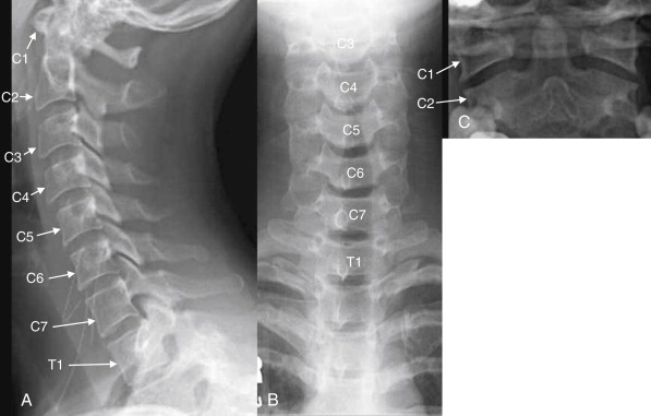
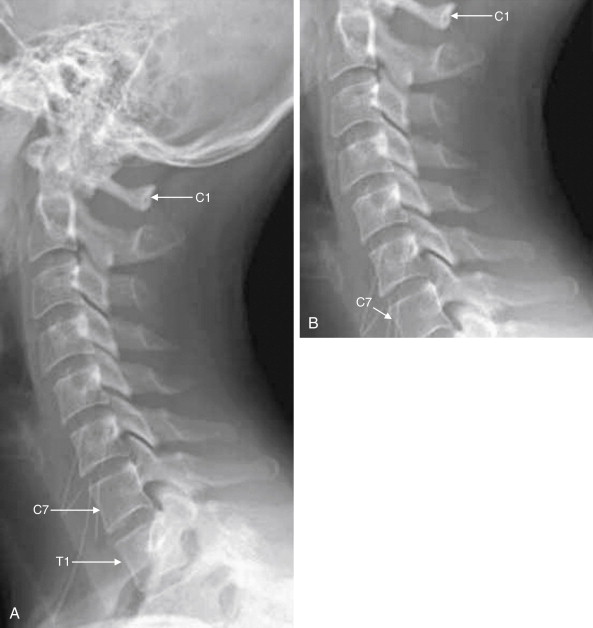
Normal Features of the Lateral X-ray


The lateral x-ray ( Figures 3-8 through 3-13 ; see also 3-19 and 3-20 ) provides information about gross fractures, as well as alignment of vertebral bodies relative to one another. In addition, prevertebral soft tissue widening may suggest soft-tissue hematoma or swelling, a surrogate marker of fractures that may themselves be invisible on plain film. The x-ray must visualize the cervical spine from the skull base to the C7-T1 (cervical seventh vertebra–thoracic first vertebra) junction. This is not an arbitrary definition of an adequate plain film. An x-ray that fails to visualize the entire cervical spine and its junctions with the adjacent skull and thoracic spine may miss injuries. Widening of the space between the C1 vertebra and the skull base may be a subtle indication of a devastating occipital–cervical dissociation—although this injury is usually clinically evident with a moribund patient with quadriplegia. At the caudad end of the cervical spine, it is essential to visualize the C7-T1 junction to avoid missing subluxation of these vertebral bodies relative to one another. This injury is made more likely by the sudden change in the mobility of the spine, from the highly mobile cervical spine to the relative immobile thoracic spine, which is supported by the buttresses of the ribs.


Figure 3-9


Adequate and inadequate lateral cervical spine x-rays.

A, An adequate lateral cervical spine x-ray, showing the entire cervical spine and its cephalad border (the skull base) and caudad border (T1). B, The image is inadequate because C1 and T1 are not seen fully. Fractures or subluxation at these locations would be missed. The x-ray should be repeated, perhaps using special views such as the swimmer’s view to visualize the C7-T1 junction, or computed tomography could be used.


Figure 3-10


Interpretation of the lateral cervical spine x-ray.

A normal lateral cervical spine x-ray, with (A) and without (B) labels.

The spine should be inspected for four curved, roughly parallel lines:

  • 1

    Anterior longitudinal ligament line (follows the anterior border of the vertebral bodies)


  • 2.

    Posterior longitudinal ligament line (follows the posterior border of the vertebral bodies)


  • 3.

    Spinolaminar line (follows the anterior border of the posterior spinous processes, where the lamina converge)


  • 4.

    Spinous processes line (follows the posterior border of the posterior spinous processes and does not fully parallel the other lines due to the increasing length of the spinous processes from C1 to C7)


    The spinal canal, which houses the spinal cord, lies between lines 2 and 3.


    If all lines are intact, the vertebral bodies should be properly aligned and the spinal canal should be preserved.


Figure 3-11


Evaluation of predental space.

On lateral cervical spine x-ray, the predental space should be evaluated. Several injury patterns can widen this space. Fracture of the ring of C1 can allow the anterior portion of the ring to migrate anteriorly with respect to the dens. Dens fracture can allow posterior migration of the dens relative to the ring of C1. Subluxation of the transverse ligament can allow widening of this space. Patients with rheumatoid arthritis are at particular risk of this latter abnormality.


Figure 3-12


Prevertebral soft tissues.

The lateral cervical spine x-ray should be examined for the width of prevertebral soft tissues. Widening suggests cervical spine injury with prevertebral soft-tissue swelling or hematoma, even in the absence of visible fracture. Lack of widening is relatively reassuring, as a fracture or ligamentous injury would be expected to be accompanied by some degree of soft-tissue swelling or hemorrhage.

In adults, soft tissues should be less than 7 mm in width at C2 and less than 5 mm at C3 and C4.

A rule of thumb in children is that the prevertebral soft tissues should be less than half the width of the adjacent vertebral body. False widening may be seen on expiratory films in children younger than 2 years, particularly if images are obtained during crying, which creates forced expiration.


A normal lateral cervical spine image shows a gentle cervical lordosis—a curve with its convex border oriented anteriorly (see Figure 3-10 ). This lordosis may be straightened slightly due to the presence of the cervical collar. When all cervical vertebrae are intact and in normal alignment with one another, this cervical lordosis results in four parallel curved lines, for which the lateral x-ray should be inspected (the numbered lines in Figure 3-10 ):


  • 1.

    The anterior longitudinal ligament line, which follows the anterior border of the vertebral bodies.


  • 2.

    The posterior longitudinal ligament line, which follows the posterior border of the vertebral bodies.


  • 3.

    The spinolaminar line, which follows the anterior border of the posterior spinous processes, where the lamina converge.


  • 4.

    The spinous processes line, which follows the posterior border of the posterior spinous processes. It does not fully parallel the other lines because of the increasing length of the spinous processes from C1 to C7. The space between the posterior longitudinal ligament line and the spinolaminar line is the spinal canal. If these lines are intact and parallel, the spinal canal should be intact, and the spinal cord should be safely contained within it.


In addition, the lateral film should be examined with attention to the following:


  • 5.

    The predental space (see Figure 3-11 ), which separates the dens from the anterior ring of C1. Widening suggests dens or C1 ring fracture, or subluxation of the transverse ligament, which binds the dens to the anterior ring of C1. In adults, this space should be no more than 3 mm, and in children it should be no more than 4 to 5 mm.


  • 6.

    Prevertebral soft tissues (see Figure 3-12 ). Widening suggests cervical spine injury with soft-tissue swelling or hematoma. In adults, this distance should be less than 7 mm at C2 and less than 5 mm at C3 and C4. In children, a commonly cited distance is less than half the width of the adjacent vertebral body. False widening may occur in children under the age of 2 years if the image is obtained during expiration. Below C4, the airway moves anteriorly, the esophagus occupies the prevertebral space, and soft-tissue widths vary considerably, usually between 10 and 20 mm in adults. Soft-tissue width exceeding the width of the adjacent vertebral body suggests injury.


  • 7.

    The spinal facet joints ( Figure 3-13 ), which should overlap like shingles on a roof. Decreased overlap can occur in the case of a jumped or perched facet joint.


    Figure 3-13


    Assessment of facet joints.

    A, Lateral cervical spine x-ray. B, Close-up. The facets should overlap like shingles on a roof. In the case of jumped or perched facet joints, the degree of facet overlap at the level of injury will be less than the overlap at uninjured levels. The facets can be recognized by their rhomboid shape in profile. Fracture through the facets and lamina is also common and should be looked for carefully.


  • 8.

    Widening of the distance between posterior spinous processes, which can indicate fracture or ligamentous injury.


Normal Features of the Anterior-posterior X-ray


The AP x-ray ( Figure 3-14 ) provides information about lateral alignment of vertebral bodies with one another. A small number of additional fractures ( particularly oblique fractures) may be noted on the AP x-ray, and subtle abnormalities from the lateral film may be confirmed. The posterior spinous processes should be centered in the midline and aligned with one another. The cortex of each vertebral body should be intact. The height of and spacing between adjacent vertebral bodies should be uniform.


Figure 3-14


Anterior–posterior (AP) normal cervical spine x-ray.

The AP cervical spine x-ray should be inspected for gross fractures. The intervertebral spacing (double arrows) should be symmetrical if the intervertebral discs (not visible on x-ray) are intact. The posterior spinous processes (black arrowheads) should project directly backward out of the plane of the x-ray and should be aligned with one another. In cases of unilateral jumped facet joint, rotation of one vertebral body relative to the adjacent bodies causes the posterior spinous process to project at an angle and thus not be aligned with the processes of other vertebrae.


Open-Mouth Odontoid X-ray


The open-mouth odontoid view ( Figures 3-15 and 3-16 ) is essential for evaluation of two important injury patterns:


  • Burst fractures of the C1 ring, also called Jefferson fractures


  • Fractures of the odontoid process or dens, which is a structure of C2


Figure 3-15


Adequate and inadequate open-mouth odontoid view x-ray.

An adequate open-mouth odontoid view must visualize the entire dens and the lateral borders of C1 and C2. An incompletely visualized dens could result in an undiagnosed dens fracture. The lateral borders of C1 and C2 must be seen to assess for misalignment, which can occur in the setting of C1 burst fracture, in which the lateral masses of C1 are displaced laterally.

A, An adequate view. The lateral borders of C1 and C2 are visible and align normally. The spaces between the dens and the lateral masses of C1 are symmetrical. The entire dens is visible and appears intact. B, An inadequate view with the tip of the dens and the lateral masses of C1 and C2 cropped. Alignment and fracture cannot be assessed.


Figure 3-16


Normal open-mouth odontoid view x-ray.

The open-mouth odontoid view is essential for evaluation of potential dens fractures and fractures of the C1 ring.

A, Routine open-mouth odontoid image. B, Close-up of the region of interest, which includes C2 with the dens, as well as the lateral masses of C1.


The open-mouth odontoid view is so called because it is obtained with the patient’s mouth opened as wide as possible, with the x-ray tube aimed into the open mouth. This gives a direct view of C1 and C2. Issues that may prevent adequate visualization include an obtunded or uncooperative patient who is unable to comply with this maneuver; a patient with trismus, temporomandibular joint disease, or other injuries (e.g., mandibular fractures) that prevent full opening of the mouth; and the presence of significant metal dental work. Sometimes, the cervical spine collar may restrict mouth opening too much to allow an adequate open-mouth odontoid view. When an adequate open-mouth odontoid view cannot be obtained, CT should be performed to avoid a missed injury of C1 or C2.


An adequate open-mouth odontoid view visualizes the entire dens and the lateral margins of both C1 and C2. A fully visualized dens is essential for evaluation of dens fractures. The cortex of the dens should be carefully inspected for defects. Shadows of overlying structures such as central incisors can simulate or hide fractures, so a wide-open view with no overlap of teeth with the dens is desirable. When the ring of C1 is intact, the lateral margins of C1 should align with the lateral margins of C2. When fractured, C1 typically “bursts,” with the fracture fragments spreading outward. Consequently, an indirect sign of C1 fracture is misalignment of the lateral margins of C1 with the lateral margins of C2. Frequently, the lateral margins of C1 appear displaced laterally compared with the lateral margins of C2, although medial displacement of C1 is also possible. This finding may be unilateral or bilateral. When C1 is intact and the patient is facing directly forward, the distance between the dens and the medial borders of the C1 ring should be bilaterally symmetrical. When C1 is fractured, displacement of fracture fragments typically renders this distance asymmetrical. The lateral margins of C1 and C2 may be hidden by radiopaque dental fillings, especially if the patient’s mouth is not fully opened.


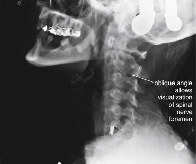
The standard three-view series just described is sometimes augmented with additional plain x-ray views. Adding two oblique views allows visualization of the pedicles, lamina, and neural foramina. Although this technique may be useful in selected cases, this “five-view” technique has been compared with the standard three views and does not detect additional injuries at a rate high enough to make five views a useful standard. The five-view series was insensitive (44%) compared with CT in a high-risk group of patients with altered mental status and a high rate of cervical spine injury (>10%). CT should be obtained if subtle lamina, pedicle, or neural foramen injuries are suspected.


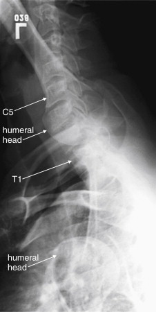
In cases in which the C7-T1 junction is not visualized on the lateral x-ray, “swimmer’s” ( Figure 3-17 ) or “traction” views may allow visualization of this region. In a swimmer’s view, the patient is positioned with the arm closer to the x-ray detector raised above the head. This elevates the humeral head above the C7-T1 junction, preventing it from obscuring this area. The opposite arm is held at the patient’s side, resulting in that humeral head lying somewhat lower that the C7-T1 junction. Variations on this theme include having the patient raise both arms directly in front of the body or over the head. In a traction view, a health care worker pulls on the patient’s arms from a position at the foot of the bed, distracting the humeral heads down to reveal the C7-T1 junction – a method now discouraged because of the possibility of worsening spinal injury. When these maneuvers do not allow adequate visualization of C7-T1, CT is indicated. In many cases, these views are skipped in favor of CT. Flexion and extension views ( Figure 3-18 ) are sometimes obtained to assess for ligamentous instability—the evidence for these views is discussed in detail later.


Figure 3-17


Swimmer’s view x-ray of the cervical spine.

A swimmer’s view is a lateral cervical spine x-ray in which the patient is positioned with one arm raised above the head. This position tilts the shoulder girdle, elevating one humeral head and depressing the other, thus revealing the C7-T1 junction. Other variations on the swimmer’s position are sometimes used, including raising both arms above the head. The swimmer’s view is only necessary when the C7-T1 junction is not visualized on a standard lateral x-ray. Today, computed tomography is more commonly used to visualize this region.


Figure 3-18


Flexion and extension x-rays of the cervical spine.

Flexion (A) and extension (B) views may be performed to evaluate for ligamentous injury if plain films in neutral position do not show fractures or subluxation but the patient has persistent pain. The patient is asked to flex and extend the cervical spine actively, stopping if pain or neurologic symptoms develop. Subluxation suggests a ligamentous injury. Passive flexion and extension (in which the patient is manipulated by the examiner) should never be used, because this may cause cervical spinal cord injury. The utility of flexion–extension views is an area of controversy, but generally these are not useful in the evaluation of acute trauma because patients with acute pain are often unable to flex or extend sufficiently to exclude ligamentous injury.


Computed Tomography of the Cervical Spine


CT scan evaluates for fractures and dislocations with high sensitivity and specificity. Soft-tissue injuries are demonstrated less directly and accurately ( Box 3-1 ). CT scan should be performed in several situations ( Box 3-2 ):


  • As a follow-up to plain x-rays to further evaluate any fracture, dislocation, or soft-tissue abnormality on x-ray.


  • As a follow-up study when adequate x-rays cannot be obtained. Examples include obese patients, obtunded or intoxicated patients, and patients with pre-existing spine disease.


  • As the primary imaging study (rather than plain x-rays) when high pretest probability of cervical spine injury is present. It makes little sense to perform plain x-rays in this circumstance, because abnormal plain films would mandate CT and because normal plain films should be suspected of having missed cervical spine injury.


Interpreting Cervical Computed Tomography


Interpretation of cervical CT can be based on many of the same criteria used for plain x-ray. We make some direct comparisons of imaging findings on CT and x-ray, so skills you may already have from x-ray can be translated to CT. For those with little experience with either modality, starting with CT may prove easier, with CT findings then clarifying subtle findings on x-ray. We take a step-by-step approach, using the sagittal, coronal, and axial images for different purposes. Each image series should be reviewed, because fractures in the plane of a given image series are difficult to see in that series but are readily apparent in perpendicular planes. We spend relatively little time up front on normal findings; instead, we concentrate on pointing out abnormalities in the figures that follow, with comparison to normal findings.


CT has high resolution for bony injury and directly detects fractures and dislocations. Modern CT scanners allow multiplanar and three-dimensional reconstructions, facilitating injury characterization. Image data is helically acquired as the patient passes through the CT gantry, typically at 1-mm or submillimeter slice thickness. Reconstructions are performed in sagittal, coronal, and axial planes ( Table 3-2 ). The sagittal plane yields information similar to that from the lateral plain x-ray. The coronal plane yields information similar to that from the AP and odontoid plain x-ray views. Axial views give detailed anatomy of individual vertebral bodies, including clear views of the lamina, pedicles, transverse foramen enclosing the vertebral arteries, and spinal canal. Although the spinal cord is not well visualized on CT, the preceding image sets allow the canal to be carefully inspected for fracture fragments or dislocations that might impinge on the spinal cord. CT is considered to have outstanding sensitivity for fractures and dislocations—a normal CT viewed on bone windows effectively rules out these injuries. Nevertheless, it remains common practice to continue spine immobilization following a normal CT if the patient cannot be clinically evaluated for neurologic complaints or continued pain, though recent studies suggest a low risk of unstable cervical injuries following normal CT (see later discussion).


TABLE 3-2

Information Provided by Various Computed Tomography Image Planes


Abnormality Sagittal Images Coronal Images Axial Images
Three-column stability Yes No Yes
AP subluxation Yes No No
Lateral subluxation No Yes No
Loss of vertebral body height Yes Yes No
Loss of disc height Yes Yes No
Burst injury Yes Yes Yes
Nondisplaced fractures Yes, if not in sagittal plane Yes, if not in coronal plane Yes, if not in axial plane
Retropulsion of fragments into spinal canal Yes No Yes


Step 1: Examine the Sagittal Computed Tomography Reconstructions


The sagittal CT reconstructions provide detailed information about the AP alignment of the cervical spine, as well as fractures or subluxations that may impinge on the spinal canal. Start your evaluation by selecting bone windows, and then move to a slice in the middle of the sagittal series, corresponding to the midsagittal plane ( Figure 3-19 ). If you are experienced in interpreting cervical spine x-rays, this image should look familiar—it strongly resembles the lateral cervical spine x-ray, without the confusing overlay of bones and soft tissues from other planes. Just as with the lateral x-ray view, the midsagittal CT image allows assessment of alignment, using the curves of the anterior and posterior longitudinal ligaments and the spinolaminar line. In this view, the spinal canal can be seen in detail and inspected for any fracture fragments or subluxation of vertebral bodies that could impinge on the spinal cord. Remember that you are only looking at a single plane—you need to scroll laterally to the patient’s right and then left to perform these same steps in planes moving away from the patient’s midline. In the midsagittal plane, notice how large the dens is—perhaps you did not appreciate this on x-ray, but look now at the lateral x-ray for comparison. Check the contour of the dens for fracture lines, and if fracture is present, inspect for retropulsion of the dens into the spinal canal. Inspect the predental space for widening. Look at prevertebral soft tissues for increased thickness suggesting soft-tissue injury. Inspect each vertebral body for fracture lines. Check the spinal lamina and posterior spinous processes for fracture. Notice that in the midsagittal plane, the facet joints are not visible. These are lateral structures and are seen in the far lateral parasagittal images ( Figure 3-20 ). Inspect these joints for unilateral or bilateral dislocation (jumped facets, shown in a later figure). At the cephalad limit of the cervical spine, inspect the articulation of the occipital condyles with C1 (see Figure 3-20 ). It may take you some time to become accustomed to imagining the cervical spine in three dimensions as you scroll through it in this plane.


Figure 3-19


Normal mid-sagittal computed tomography (CT) image, compared with normal lateral cervical spine x-ray.

This 24-year-old female hydroplaned on a wet road at 45 mph and complained of midline cervical spine tenderness. Her CT is reviewed to demonstrate normal findings.

A, When reviewing CT sagittal images, follow the paradigm of the lateral x-ray. First, select bone windows. Next, select the midsagittal CT image and note the alignment of vertebral bodies, using the same four lines used for evaluating alignment on the lateral x-ray (see Figure 3-10 ). Then, inspect each vertebra for fractures (shown in subsequent figures). Notice how the facet joints are not visible in the midsagittal plane. Also notice how large the dens is and how small the ring of C1 is. Prevertebral soft tissues can be evaluated using the same criteria as for x-ray. B, Lateral x-ray for comparison.


Figure 3-20


Normal parasagittal computed tomography (CT) image, compared with lateral cervical spine x-ray.

A, In this far lateral parasagittal CT image, the facet joints can be seen articulating normally, like shingles on a roof. The vertebral bodies are not seen in this plane, as we are far from the midline. The occipital condyles are seen articulating with C1. B, Lateral x-ray for comparison. Notice how much clearer the occipital–cervical junction is on CT.


Step 2: Inspect the Coronal Images


Use the coronal CT images ( Figure 3-21 ) to simulate the open-mouth odontoid and AP cervical x-rays. Scroll through the “stack” of coronal images until you see the odontoid process projecting between the lateral masses of C1. Check for the same features you would expect on the open-mouth odontoid view. The lateral masses of C1 and C2 should align along their lateral borders. The spaces between the odontoid process and the lateral masses of C1 should be symmetrical. The odontoid process itself should have a smooth contour, with no fracture lines present. Once you have completed this evaluation, scroll in anterior and posterior directions through the stack of images, inspecting for fractures of the vertebral bodies, facets, and transverse processes. Fractures in the sagittal plane are visible on coronal images, and may be missed on the sagittal images reviewed first. Look for lateral displacement of vertebral bodies with respect to one another. Spend some time reviewing the figures in this chapter to familiarize yourself with the most common fracture patterns.


Figure 3-21


Normal coronal computed tomography image, compared with odontoid view x-ray.

A, Same patient as Figures 3-19 and 3-20 . A coronal image centered on the odontoid (dens) and C1, simulating the open-mouth odontoid x-ray. CT findings of a normal dens are the same as those seen on open-mouth odontoid x-ray, and deviation from normal should heighten suspicion for injury, even when a fracture line is not seen. Subluxation without fracture may be present. The lateral borders of the C1 and C2 vertebral bodies should align. Fractures of the ring of C1 (Jefferson fractures) commonly result in radial spread of C1 fragments, disturbing this normal alignment. The spaces between the lateral masses of C1 and the odontoid process should be bilaterally symmetrical. C1 fractures can result in asymmetrical spread of fragments, and subluxation of the transverse ligament can also result in asymmetry. The odontoid process should be smoothly contoured with no visible fracture lines. A slight notched appearance on each side of the base of the dens is normal. B, Open-mouth odontoid x-ray for comparison.


Step 3: Inspect the Axial Computed Tomography Images


The axial CT images ( Figure 3-22 ) have no immediate analogue in the normal three-view x-ray series. They can provide additional information not readily seen on the sagittal and coronal views. Particularly, they demonstrate fractures of the canals housing the vertebral arteries (foramen transversarium), which are more difficult to assess on other views. They also provide good views of fractures in the sagittal and coronal planes, which may not be seen well on those image series as they lie parallel to the plane of the image. From the sagittal images, you should already have a good idea of the alignment of the cervical spine, although the axial images can also demonstrate jumped facet joints. The axial images provide an en face view of the spinal canal. As you scroll from the level of C1 to T1, imagine yourself traveling down the spinal canal, and watch for fracture fragments that narrow the canal and may impinge on the spinal cord. Check the body, pedicles, lamina, and transverse and posterior spinous processes for fractures. We review many abnormal findings on the axial images in the figures throughout this chapter (see list, Table 3-1 ).


Figure 3-22


Normal axial computed tomography image.

Same patient as Figures 3-19 through 3-21 . An axial image shows a cervical vertebra in cross section. The vertebral body, spinal canal, pedicles, lamina, and base of the posterior spinous process are visible. It takes some practice to become accustomed to the normal appearance of vertebrae in axial section. They are irregular structures and never lie completely within a single axial plane. Apparent discontinuities in the ring may be visible on some slices but may not represent fractures—instead, they simply reflect the irregular contour of the vertebrae passing in and out of the image plane. A, B, Two sequential slices.


Clinical Decision Rules: Who Needs Cervical Spine Imaging?


Indications for cervical spine imaging have been studied extensively, resulting in two well-validated clinical decision rules (CDRs) to aid the clinician in identifying patients who require cervical spine imaging. We review both rules in detail, discussing their strengths and weaknesses.


The National Emergency X-radiography Utilization Study


The National Emergency X-radiography Utilization Study (NEXUS) was a prospective study of 34,069 patients at 21 U.S. medical centers, examining blunt trauma patients undergoing cervical spine imaging ( Box 3-3 ). This study was well planned and conducted and identified 818 patients with cervical spine injuries, comprising 2.4% of the study population. The study evaluated a CDR consisting of five clinical criteria, which had been suggested by prior studies ( Box 3-4 ). Cervical spine imaging was considered necessary if any one of the five was present. The investigators prospectively defined a group of clinical unimportant cervical spine injuries which they did not expect their proposed rule to identify, as they would not be anticipated to lead to patient harm if undetected. This rule proved 99% sensitive, though only 12.9% specific for clinically important acute cervical spine fracture. The negative predictive value of the rule was 99.8%, with a positive predictive value of only 2.7%. Application of the rule would have reduced cervical spine imaging by 12.6%. The rule failed to identify 8 of 818 injuries—2 which would have been clinically significant, 1 of which was treated surgically. Application of this rule is estimated to miss one injury in 125 years of clinical practice by a typical emergency physician.


The Canadian Cervical Spine Rule


The Canadian Cervical Spine Rule (CCR) ( Figure 3-23 ) is a classic example of a methodologically rigorous CDR. CDRs are aids to bedside decision making, intended to reduce the cost, time, and adverse consequences of care, such as radiation exposures from diagnostic imaging. CDRs must be rapid to apply, inexpensive, and sensitive to avoid missing important pathology. They must be specific enough to reduce subsequent test utilization; otherwise, they fail their primary objective. Typically, CDRs use readily available information from the history and physical examination, occasionally supplemented by simple, rapid, and inexpensive bedside tests such as urinalysis.


Figure 3-23


The Canadian Cervical Spine Rule.

GCS , Glasgow Coma Score; MVC , motor vehicle collision.


Figure 3-24


Cranial–cervical junction x-ray: Occipital condyle fracture.

A, Lateral cervical spine x-ray. B, Close-up of atlanto-occipital junction. Fractures of the occipital condyle are extremely difficult to see or invisible on plain x-ray, as this lateral cervical spine x-ray illustrates. Computed tomography (CT) scan of the region clearly demonstrated a fracture (see Figure 3-25 ), but the complex overlap of multiple structures at the junction of the skull base and C1 vertebral body masks the pathology on x-ray. The cervical spine alignment appears normal. This patient also has a C2 fracture known from CT but not seen on this view.


Figure 3-25


Cranial–cervical junction CT: Occipital condyle fracture.

A, On this sagittal CT reconstruction, a fracture through the occipital condyle is seen, with a cortical defect and step-off. B, The normal opposite side for comparison. Both images are far lateral to the midline. C, D, Close-ups from A and B, respectively.


Figure 3-26


Cranial–cervical junction CT: Occipital condyle fracture.

A, On this coronal CT image, a fracture through the right occipital condyle is seen, with a cortical defect and step-off. Compare with the normal opposite side. B, Close-up showing this fracture in detail.


Figure 3-27


Cranial–cervical junction CT: Occipital condyle fracture.

A, B, On these axial views, a fracture through the right occipital condyle is seen, with a cortical defect and step-off. Compare with the normal left occipital condyle. C, D, Close-ups from A and B, respectively, show this fracture in detail. Although this step-off is subtle, it should not be confused with a reconstruction artifact. Note that other bony cortices in horizontal alignment with the fracture appear intact. If reconstruction artifact were at fault, cortices would appear disrupted in a horizontal line spanning the entire image.


Figure 3-28


C1 Jefferson burst fracture.

A, Lateral cervical spine x-ray. B, Close-up.

C1 burst fractures (also called Jefferson fractures) result from axial force applied to the cervical spine, crushing the ring of C1 between the skull base and the body of C2. A common mechanism is diving into a pool and striking the head on the pool bottom. The resulting fragments of the C1 ring typically spread radially, and plain x-ray findings include a widened predental space (visible on a lateral x-ray), or laterally displaced margins of the C1 ring on an open-mouth odontoid x-ray. However, even a badly comminuted fracture can be difficult to detect on plain x-ray. Computed tomography (CT) is so widely used in the evaluation of potential cervical spine injuries that plain x-rays of this injury are becoming increasingly rare. In this patient, CT revealed a C1 fracture ( Figures 3-29 through 3-31 ). This lateral x-ray with the patient in a halo device does not reveal the fracture directly, although the prevertebral soft tissues are slightly widened—the normal measurement being 7 mm or less. The predental space, which can be widened in burst fractures, is normal. This is not due to a failure of x-ray to detect an abnormality but rather due to the absence of predental widening in this patient, as shown on the patient’s CT ( Figures 3-29 through 3-31 ).


Figure 3-29


C1 Jefferson burst fracture: Cervical spine computed tomography (CT) without contrast, bone windows.

Same patient as in Figure 3-28 . In these axial views, the ring of C1 is clearly fractured in multiple locations, with some radial spread of fracture fragments. Two slices are shown to capture both the anterior (A) and the posterior (B) portions of the ring of C1, as the position of the patient in the CT scanner prevents the entire ring from being seen in a single slice. C, Close-up from B. Discriminating fractures from the normal appearance of vertebral bodies as they pass in and out of the image plane takes practice. The task is easier when using a complete digital stack of images than when looking at selected images, as in a textbook like this.


Figure 3-30


C1 Jefferson burst fracture, noncontrast CT, bone windows.

Same patient as in Figure 3-28 . A, B, Sagittal computed tomography (CT) reconstructions, with close-ups from the same slices ( C and D, respectively). The optimal CT plane for detecting a fracture depends on the predominant direction of the fracture plane. In this patient, the sagittal reformations look nearly normal, as many of the C1 fractures are in a sagittal plane parallel to the sagittal plane of reconstruction. One fracture line through the anterior portion of C1 runs in a coronal plane and is therefore visible on the sagittal views. The left lamina fracture seen on the axial reconstructions is also in a coronal plane, intersects the sagittal plane, and is thus visible on the sagittal views.


Figure 3-31


C1 Jefferson burst fracture, noncontrast CT, bone windows.

Same patient as in Figure 3-28 . A burst fracture of C1 is often recognized on plain x-ray using the open-mouth odontoid view (see normal odontoid image, Figure 3-16 ). A, B, Coronal planar CT reformations (with close-ups in C and D, respectively) mimic the odontoid x-ray view. The fractures in this patient are not directly visible, as they lie predominantly in the coronal plane, parallel to the plane of reconstruction. However, the radial dispersion of the fracture fragments has caused a classic abnormality, malalignment of the lateral masses of C1 with the margins of the C2 vertebral body. As a result of the fractures, the left-hand portion of the C1 ring is freely mobile and has shifted laterally with respect to C2. In addition, the facet joint between C1 and C2 is widened, as is the joint space between the occipital condyle and C1.


Figure 3-32


C1-2: Atlantoaxial rotary fixation.

Rotation of C1 on C2 is a normal joint motion—within limits. Excessive rotation at this level can result in facet dislocation (“jumped facet”), locking the joint in a malaligned position and preventing the head from assuming a midline position. This patient was in an altercation in which her assailant violently twisted her head. This computed tomography scout image shows the head to be turned approximately 45 degrees toward the patient’s left shoulder. Figures 3-33 and 3-34 evaluate this injury in more detail.


Figure 3-33


C1-2: Atlantoaxial rotary fixation.

Same patient as Figure 3-32 , who has experienced a rotational injury to the spine. A, The skull and C1 moved as a unit, rotating toward the patient’s left shoulder relative to C2 and the remainder of the cervical spine. B, C2 and the remainder of the cervical spine are pointed toward the patient’s right shoulder. The facet joints of C1 and C2 are both visible, having rotated relative to one another. The C1 facet has subluxed completely posterior to the C2 facet. Normally, the two facets cannot be seen in the same axial image, as one is directly cephalad to the other.


Figure 3-34


C1-2: Atlantoaxial rotary fixation.

Same patient as Figures 3-32 and 3-33 , who has experienced a rotational injury to the spine. On these axial images, note how the head and C1 are facing the left shoulder (A), while C2 is directed toward the right shoulder (B).


Figure 3-35


C1-2: Atlantoaxial rotary fixation.

Same patient as Figures 3-32 to 3-34 , who has experienced a rotational injury to the spine. On these axial images, note how the rotation of C1 on C2 has changed the normal position of the canals housing the vertebral arteries (transverse foramen). Because of the patient’s rotated position, none of canals is seen completely on these images. Circular markers have been added to this figure to indicate the position of the vertebral arteries in the canals. In the center, they have been superimposed to show how rotation of this type could crimp or tear the vessels. This type of rotational injury can result in vertebral artery dissection or even transection. The patient underwent a computed tomography (CT) angiogram of the neck that showed no arterial injury. CT angiography for evaluation of cervical arterial injuries is discussed in Chapter 4 .


Figure 3-36


C1-2: Atlantoaxial rotary fixation.

Same patient as Figures 3-32 to 3-35 , who has experienced a rotational injury to the spine. On these sagittal CT images, alignment looks surprisingly normal when viewing a nearly midsagittal image (B). However, sagittal images through far right lateral positions (A) and far left lateral positions (C) reveal that the C1-2 facet joints are completely subluxed. The mid-sagittal image looks normally aligned because the rotation occurred about a midsagittal pivot point. The central spinal canal is preserved in this rotational injury, and the patient had no neurologic deficits. This type of injury can severely injure the vertebral arteries, although fortunately, no injury occurred in this case.


Figure 3-37


C1-2: Atlantoaxial rotary fixation.

Same patient as Figures 3-32 to 3-38 , who has experienced a rotational injury to the spine. On these coronal CT images, the usual open-mouth odontoid appearance with a midline dens flanked by the lateral masses of C1 cannot be found, due to rotation of C1 on C2. A, Instead, the right lateral mass of C1 is visible, but not positioned normally above the C2 lateral mass. B, The left lateral mass of C1 is visible, but again the lateral mass of C2 is not in normal position below it. C, A normal coronal section for comparison.


Figure 3-38


C1-2: Atlantoaxial rotary fixation.

Same patient as Figures 3-32 to 3-37 , who has experienced a rotational injury to the spine. This lateral plain x-ray appears more like a standard oblique view due to the rotational injury. Oblique x-ray views are discussed in more detail in the text. In some institutions, they are part of the standard x-ray series.


Figure 3-39


C1 posterior arch fracture, noncontrast CT, bone windows.

This patient sustained a Jefferson burst fracture of C1. Among the multiple fractures were posterior arch fractures, seen on these axial (A) and sagittal (B) views. These injuries can occur in isolation or with a comminuted burst pattern. As a result of the ring shape of C1, solitary fractures are rare, and two or more fractures are usually seen. Axial computed tomography images often cause confusion in novice readers, because the irregular three-dimensional shape of the vertebral bodies and asymmetrical positioning of the patient in the scanner often conspire to create the appearance of fracture when none exists. When an apparent defect in bone is found, always look through adjacent images in the digital stack to ensure that you are not seeing an artifact caused as the vertebral body passes out of the image plane. Although ring fractures of C1 can create fracture fragments that impinge upon the spinal cord, in this case, the spinal canal is patent.


Figure 3-40


C2 dens fracture, type II.

A, Lateral cervical spine x-ray. B, Close-up from A. C, The same image without labels.

Fractures of the odontoid process or dens may be visible on the lateral cervical spine plain x-ray. Findings may include widening of the predental space or prevertebral soft tissues or actual cortical defects of the dens itself. The C1 ring may be intact but displaced posteriorly as well. The open-mouth odontoid plain x-ray view is also helpful for detecting this injury, although computed tomography is more sensitive and specific. In this patient, a cortical defect is present and the dens appears retropulsed. The anterior portion of the C1 ring is directly cephalad to the C2 body, instead of anterior to C2, which would be normal. The posterior ring of C1 is posteriorly displaced, so the posterior spinal line (also called posterior longitudinal ligament line) is disrupted. The dens itself is difficult to recognize. The prevertebral soft tissues are also widened, exceeding 7 mm at C2. Compare with the CT [in Figure 3-41 ].


Figure 3-41


C2 dens fracture, type II.

Same patient as in Figure 3-40 . A, In this midsagittal computed tomography image, a type II dens fracture is seen. The fractured dens is slightly retropulsed into the spinal canal, though no significant stenosis has resulted. The predental space is not wide. The prevertebral soft tissues anterior to C1 and C2 are somewhat widened, likely indicating hematoma. B, Close-up.

Look again at the lateral cervical spine x-ray in Figure 3-40 for comparison. As in that figure, the C1 ring here is attached to the dens by the transverse ligament and has moved posteriorly with the dens. This fracture is nearly parallel to the axial plane and is more difficult to identify on the standard axial images in Figure 3-42 .


Figure 3-42


C2 dens fracture, type II, noncontrast CT, bone windows.

Same patient as in Figures 3-40 and 3-41 , axial images (A, B). This type II dens fracture is nearly parallel to the axial plane and is therefore almost undetectable on the axial images. At the posterior aspect of the base of the dens, a fracture line extends horizontally, and small fracture fragments have been slightly retropulsed into the spinal canal. Look at the sagittal images in Figure 3-41 for comparison.


Figure 3-43


C2 dens fracture, type II. Same patient as in Figures 3-40 through 3-42 .

A, In this coronal CT reconstruction, a transverse fracture line is seen extending across the base of the dens. An open-mouth odontoid x-ray would give a similar view of this fracture, though one was never obtained in this patient. B, Close-up.


Figure 3-44


C2 dens fracture, type III.

A, Lateral cervical spine x-ray. B, Close-up. In a type III dens fracture, the fracture line extends into the body of the C2 vertebra. This patient was noted to have a type III dens fracture on CT scan. A lateral cervical spine x-ray was subsequently obtained after the patient was placed in a halo traction device. A fracture line through the dens and cephalad portion of the body of C2 is seen, with the dens fracture fragment distracted in a cephalad direction by the traction device. Figures 3-45 through 3-47 demonstrate this fracture in more detail in CT images.


Figure 3-45


C2 dens fracture, type III.

Same patient as in Figure 3-44 . Sagittal CT images with close-ups. These sagittal CT views delineate the fracture from Figure 3-44 in more detail. In a nearly midsagittal plane (B), this fracture resembles a type II dens fracture, with the fracture line running near the base of the dens. However, in more lateral parasagittal views ( A, right parasagittal, and C, left parasagittal), the fracture line is seen running through the lateral masses of C2, consistent with a type III fracture. Importantly, there is no significant retropulsion of fracture fragments into the spinal canal.


Figure 3-46


C2 dens fracture, type III.

Same patient as in Figures 3-44 and 3-45 . These axial computed tomography (CT) views delineate the fracture in more detail. A, The fracture line extends from the central vertebral body of C2 toward the right lateral mass. B, The fracture shows a greater degree of comminution than is evident from the lateral x-ray ( Figure 3-44 ). C, The fracture continues through the left lateral mass of C2. In all of these views, the spinal canal appears patent, and the spinal cord is faintly visible as a dark gray ellipse (because of its low density) on these bone window views.


Figure 3-47


C2 dens fracture, type III.

Same patient as in Figure 3-44 to 3-46 . A, B, These coronal computed tomography (CT) views delineate the fracture in more detail. The fracture extends across the body of C2, completely separating the dens. The fracture continues laterally into the left lateral mass of C2. C, The fracture fragment shows mild craniocaudal diastasis, with the fragment having moved cranially relative to the body of C2 (close-up from A ). Compare this with the plain x-ray in Figure 3-44 . The close-up helps to illustrate what might be seen on an open-mouth odontoid plain x-ray of this injury, had one been obtained.


Figure 3-48


C2 dens fracture, type III, noncontrast CT.

A 17-year-old male with neck pain after falling off a bicycle. The patient had a normal neurologic examination with cervical spine tenderness to palpation.

A, The odontoid x-ray shows asymmetry of the spaces between the dens and lateral masses of C1. The space on the patient’s right is wider than the space on the patient’s left. Although no fracture is visible, this finding is concerning for dens fracture or for C1 burst fracture. Compare with the normal odontoid x-ray in Figure 3-16 . B, A coronal computed tomography (CT) slice not only shows asymmetry but also confirms fracture—a type III dens fracture as it extends from the base of the dens to the body of C2. C, An axial CT image again confirms fracture. The patient was treated with halo fixation.


Figure 3-49


Hangman’s fracture of C2.

A, Lateral computed tomography (CT) scout image. B, Close-up. Scout images are usually used not for diagnosis but for selecting the region for the detailed CT scan. In this case, however, the scout images are diagnostic and give us an example of what might have been seen on lateral cervical spine x-ray, had one been obtained.

This patient has a hangman’s fracture of C2. The lateral scout image from the CT scan resembles a lateral cervical spine x-ray and shows typical findings, including subluxation of the body of C2 on C3. The body of C2 appears tipped slightly anteriorly. Fractures through the pedicles of C2 are faintly visible. The fracture is explored in detail in Figures 3-50 through 3-52 .


Figure 3-50


Hangman’s fracture of C2.

Same patient as in Figure 3-49 . In this series of parasagittal CT images traversing from the patient’s right to left ( A to E ), a hangman’s fracture is demonstrated. A, The right pedicle is fractured. B, Just right of midline, the body of C2 is seen subluxed anteriorly on C3. C4 is labeled to assist in orientation. A tiny bone fragment is seen in the spinal canal. C, Subluxation of C2 on C3 of 6 mm is seen. D, The body of C2 is also fractured. E, The left pedicle is fractured, with the fracture involving the intervertebral foramen.


Figure 3-51


Hangman’s fracture of C2.

Same patient as in Figures 3-49 and 3-50 . In this series of axial CT images (A to C), a hangman’s fracture of C2 is visible. This involves the left and right pedicles, as well as the body of C2. Fracture fragments have been retropulsed into the spinal canal. Although on plain x-ray this type of fracture often appears simple, computed tomography frequently reveals a badly comminuted fracture.


Figure 3-52


Hangman’s fracture of C2.

Same patient as in Figures 3-49 through 3-50 . In these coronal CT images (A, B), the comminuted fracture through the right C2 pedicle is visible. The remaining fractures are difficult to see because they lie predominantly in a coronal plane, parallel to the plane of these computed tomography images. This emphasizes the importance of inspecting multiple image planes to detect fractures. Fractures are usually seen in images perpendicular to the fracture plane, while images in a parallel plane may disguise fractures. Fractures in an oblique plane may be visible in axial, sagittal, and coronal planes.


Figure 3-53


Hangman’s fracture of C2.

Two lateral x-ray views of another patient with a C2 hangman’s fracture ( A, B; C same as B without labels). Compare these images with the scout computed tomography image and sagittal CT images in the prior case ( Figures 3-49 and 3-50 ). Subluxation of C2 on C3 is visible. In addition, displaced fractures through the pedicles of C2 are visible. Look at the normal rhomboid appearance of the pedicles and lamina of the lower vertebrae, and the loss of that normal appearance at C2 as a consequence of fracture. The cervical spine appears quite straight with loss of the normal cervical lordosis due to the cervical collar on the patient. Notice that the anterior and posterior spinal lines (also called anterior and posterior longitudinal ligament lines) and spinolaminar line are all disrupted by the fracture. Make a habit of inspecting these lines, which can draw your attention to fractures.


Figure 3-54


Hangman’s fracture of C2.

Close-up of the same C2 hangman’s fracture as Figure 3-53 . Compare this image with the scout CT image and sagittal images in the prior case ( Figures 3-49 and 3-50 ). Subluxation of C2 on C3 is visible. In addition, displaced fractures through the pedicles of C2 are visible. Look at the normal rhomboid appearance of the pedicles and lamina of the lower vertebrae—which is disrupted in C2 due to the fracture. The anterior and posterior spinal lines and spinolaminar line are all disrupted, as seen in Figure 3-53 .


Figure 3-55


Hangman’s fracture of C2.

Take a moment to orient yourself to the lateral x-ray and a midsagittal CT slice in the same patient. In Figure 3-56 , we focus on the region of C1 through C3, and explore the sagittal sections from the patient’s right to left, to understand this fracture in depth. A, The lateral x-ray compresses lots of information into a single plane—not all the fractures present are actually in the midline, which explains the relative lack of abnormalities on the midsagittal CT (B). Most of the fractures are through lateral structures of the C2 vertebra.


Figure 3-56


Hangman’s fracture of C2.

Sagittal computed tomography images from the same patient as in Figures 3-53 through 3-57 illustrate in more detail the abnormalities seen on the lateral plain x-ray. The sections shown are displayed from far right parasagittal (A), through the midline (K), and to far left sagittal (X). Take a moment to get oriented by looking at slice K, which shows the midline with the dens clearly demonstrated. In the far right slices starting at A, the facet joint is demonstrated. A fracture line runs through the right pedicle of C2, just anterior to the articular pillar. In the slices near the midline, the C2 body can be seen with anterior subluxation relative to C3, widening the spinal canal. In the slices approaching a left lateral position ( O to U ), a fracture is seen through the base of the spinous process and extending into the left lamina as you continue toward the patient’s left in the series. The result of the bilateral fractures is complete separation of the posterior elements of the vertebral body from the anterior elements, an unstable fracture. A perched facet (articular pillar) is seen in T to X; this injury is explored in more detail in a later figure, as it is not technically part of the hangman’s fracture pattern.

Jul 4, 2019 | Posted by in GENERAL RADIOLOGY | Comments Off on Imaging the Cervical, Thoracic, and Lumbar Spine

Full access? Get Clinical Tree

Get Clinical Tree app for offline access