Facial imaging plays an important role in the evaluation of trauma, as well as in assessment of soft-tissue infections and masses of the face. Facial imaging often overlaps with imaging of the brain, cervical spine, and soft tissues of the neck. These topics are covered in detail in dedicated chapters, though we discuss common themes in this chapter. We begin with a brief discussion of facial computed tomography (CT) protocols, followed by a guide to interpretation of facial CT. In Chapter 1 , we discussed clinical decision rules for CT of the brain, based on large multicenter studies. The evidence for facial imaging is less clear. We examine the two major indications for facial imaging, trauma and nontraumatic facial complaints such as pain, swelling, and erythema, framing our discussion with clinically based questions. We answer common questions about facial CT, such as its value relative to other modalities, such as panoramic x-ray.
Arrangement of Figures in This Chapter
Figures in this chapter are generally arranged into traumatic facial conditions and nontraumatic facial conditions. Because many figures illustrate numerous findings, you will often encounter cross-references to figures presented earlier or later in the chapter. For your quick reference, see Table 2-1 , which presents the general order of the figures.
| Content | Figure Number |
|---|---|
| Comparison of head and face computed tomography | 2-1 |
| Facial trauma | |
| Frontal bone fracture | 2-2 |
| Orbital fractures and ocular injuries | 2-3 through 2-13 |
| Midface injuries and Le Fort classification | 2-14 through 2-23 |
| Mandible injuries | 2-24 through 2-26 |
| Nontraumatic facial conditions | |
| Orbital soft-tissue infections and neoplasms | 2-27 through 2-31 |
| Sinusitis and mastoiditis | 2-32 through 2-34 |
| Parotid gland disease | 2-35 |
Imaging Options
Traditionally, facial x-rays played an important screening role in the evaluation of facial trauma and infection. However, the complex three-dimensional relationship of facial bones and sinus air spaces makes interpretation of plain x-ray difficult. Facial x-ray imaging has limited sensitivity and specificity and has been largely replaced by CT scan. Other modalities such as ultrasound play specialty roles in evaluating injuries such as ocular trauma. We focus our discussion on CT, highlighting the role of other modalities when appropriate.
What Is the Facial CT Protocol? How Does it Differ from Head CT? Is Facial CT for Trauma the Same as Facial CT for Nontrauma? When Is IV Used?
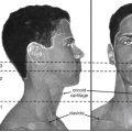
Facial CT differs from noncontrast head CT in several ways. Thinner CT sections are routinely performed to increase sensitivity for fracture. The CT dataset is processed using special bone algorithms, a different process than simply selecting bone windows to view a head CT. In addition, the CT gantry may be repositioned to allow true coronal plane source images to be acquired, in addition to the axial images acquired during noncontrast head CT ( Figure 2-1 ). In facial CT, both axial and coronal views are routinely provided for interpretation; in noncontrast head CT, axial images are the routine series. Facial CT for trauma is performed without intravenous (IV) contrast, as findings of trauma such as bony fracture, blood in sinus spaces (forming air–fluid levels), and soft-tissue swelling do not require IV contrast for identification. When CT is used for evaluation of nontraumatic facial complaints, IV contrast should be administered if possible. Neoplasms, vascular malformations, and infectious and inflammatory conditions all may show enhancement with IV contrast, aiding diagnosis. Facial CT has a narrower field of view than brain CT. For example, Figure 2-2 demonstrates that while the face is seen in detail, the posterior cranial vault and much of the brain are not within the field of view. As a consequence, if brain injury or nonfacial skull fracture is suspected, noncontrast head CT should be obtained.
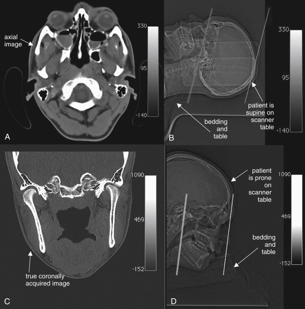
In the past, true coronal sections acquired with the patient in a prone position offered higher resolution than coronal reconstructions created from axial source images (see Figure 2-1 ). These high-resolution images have excellent sensitivity for even minimally displaced fractures. Modern multislice helical CT has the ability to create multiplanar sagittal and coronal, as well as three-dimensional, reconstructions from source data acquired with the patient in a supine position, eliminating the need to acquire true coronal images by patient and gantry repositioning. One cadaver study suggested that coronal plane facial reconstructions generated from axial fine-cut (1.25 mm) head CT images had a sensitivity of 97% for displaced fracture compared with coronally acquired images when interpreted by an experienced radiologist. The true sensitivity of facial CT is difficult to determine, as no independent gold standard for comparison is available to confirm negative CT results. Is a normal CT a true negative, or is it a false negative, having missed a fracture? This study assigns coronally acquired facial CT the role of diagnostic reference standard for comparison with coronal reconstructions from axially acquired images. In this study, facial fractures were generated in the cadavers by striking the cadaver heads in a standardized fashion. However, the exact number of fractures generated by this method is unknown, so it is impossible to determine whether either CT technique actually detected all fractures.
Why should we care about these issues as emergency physicians? Advantages of using coronal reconstructions rather than true coronally acquired images include reduced scan time, reduced radiation exposure (particularly to the radiosensitive lens of the eye), and utility in patients who cannot be repositioned for other clinical reasons, including cervical spine injuries (which prevent prone positioning) and life-threatening injuries that limit additional CT.
Interpretation of Facial Computed Tomography in the Setting of Trauma
The approach to interpretation of facial CT requires a knowledge base similar to that for head CT. Refer to Chapter 1 , in which basic features of CT, including right–left orientation, Hounsfield units, and window settings, are explained in detail. For facial CT, we rely on two primary window settings: bone windows for bony injury from facial trauma, and soft-tissue windows for soft-tissue injury from trauma and for other indications, such as assessment of soft-tissue infections and masses. When interpreting facial CT for trauma, review the entire CT using bone windows, and then repeat the process using soft-tissue windows. Throughout this chapter, you will find carefully annotated images depicting a range of pathology. The figure captions lead you through the interpretation of the specific findings, including the optimal choice of window setting. Unlike head CT, in which axial images are often the only image set reviewed, facial CT images are generally acquired and displayed in both axial and coronal planes. Sagittal planes and three-dimensional reconstructions are selectively used to depict injuries and pathology that are incompletely characterized by axial and coronal images.
A few sources of error in interpretation deserve mention here. Use of the wrong window setting prevents detection of important pathology. For example, soft-tissue windows do not allow detailed inspection of bone, so nondisplaced fractures may not be seen. Emergency physicians may not be familiar with detailed anatomy of facial bones, so normal structures such as sutures and foramen may be mistaken for fractures. If a patient has a unilateral complaint or injury, use the normal side for comparison when inspecting the CT images. Recognize that CT reconstructions often have reconstruction artifacts, such as the “seams” where two image sets are pieced together by the computer (see Figure 2-15 on page 62). These artifacts can be distinguished from fractures, as the “step-off” created by reconstruction artifact extends across the entire CT image, not just through bone. Understanding that these artifacts may exist can prevent artifact from being misconstrued as fracture. Asymmetrical positioning of the patient within the CT gantry also results in asymmetry of CT images, which may be misinterpreted by the novice as injury or pathology (see Figure 2-16 , B, on page 62 where asymmetry is caused by patient positioning). Note the patient’s position on the CT images as you begin your interpretation so that you may take position into account and avoid this pitfall.
CT for facial trauma is performed without IV contrast. Bone windows are used to evaluate most injuries, as they demonstrate both fractures and air–fluid levels well. Soft-tissue windows can depict subcutaneous hematomas and swelling, but these injuries rarely require specific therapy. Two important exceptions must be recognized. First, soft-tissue windows may reveal intracranial injury, although the field of view of facial CT does not include the entire brain, and brain (head) CT should be ordered if intracranial injury is suspected (see Chapter 1 ). Second, injuries to the globe and other orbital contents may require emergency ophthalmologic intervention and are seen on soft-tissue windows. Most remaining traumatic facial injuries are fractures and injuries to sinus spaces, best seen using bone windows. Our approach uses a cephalad to caudad orientation. Consequently, we first discuss frontal bone fractures, followed by orbital and ethmoid sinus injuries; maxillary, zygomatic, tripod, nasal, and Le Fort midface fractures; and finally, dental and mandibular injuries.
Frontal Bone Fractures
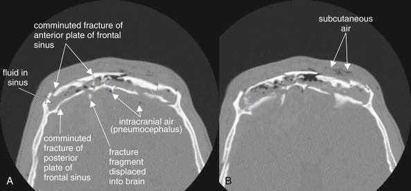
Frontal bone fractures (see Figure 2-2 ) can be isolated facial injuries or can extend intracranially. The frontal sinus has an anterior and posterior wall. Fractures to the anterior plate alone are facial injuries, requiring cosmetic surgical treatment if depressed. Fractures to the posterior plate are calvarial injuries and carry several risks, including intracranial infection (from contamination of the cerebrospinal fluid with nonsterile air and fluid from the frontal sinus), intracranial hemorrhage, and direct traumatic brain injury if fracture fragments are projected posteriorly. Inspect for frontal sinus injury first using bone windows and then using brain windows. On bone windows, examine the anterior and posterior plates for discontinuities. Anterior plate fractures may require otolaryngology or plastic surgery consultation. Posterior plate fractures require neurosurgical consultation. Some patients have a hypoplastic frontal sinus, with no airspace—the anterior and posterior plates are fused as one bone, so any fracture requires neurosurgical consultation. The normal frontal sinus is air-filled (black). Look for opacification of the frontal sinus (gray on bone windows), indicating traumatic blood. In the absence of trauma, frontal sinusitis can have a similar appearance. When fractures of the posterior plate are present, look for intracranial air (pneumocephalus, black) using bone windows. Inspect for bone fragments that have been displaced posteriorly. Switch to brain windows and inspect for intracranial hemorrhage, which will appear white (see Chapter 1 ). Posterior plate fractures should prompt additional imaging with noncontrast head CT if this has not already been obtained.
Orbital Injuries
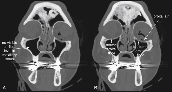
Fractures to the orbit are detected by reviewing CT images on bone windows. The plane of the fracture and direction of displacement of fracture fragments varies, so axial and coronal images should be reviewed to ensure detection of any fractures. If the patient has a unilateral injury, use the normal side for comparison. As discussed in Chapter 1 , bony injury may be seen directly as a discontinuity in the bone making up the walls of the orbit or adjacent sinus space (sometimes called a cortical defect). However, some minimally displaced fractures may be difficult to recognize directly, and indirect signs of injury may draw your attention to a likely fracture. These signs include fluid in normally air-filled spaces—the ethmoid sinuses medial to the orbit and the maxillary sinuses inferior to the orbit. An air–fluid level may be present, or the sinus space may be completely opacified with blood products. On bone windows, bone appears quite white, air appears completely black, and blood and other soft tissues appear various shades of gray. Another indirect sign of orbital fracture is air within the orbit. Again, on bone windows, air in the orbit will appear black. Air is not normally found within the orbit but may be introduced from adjacent sinus spaces when fractures occur. Figures 2-3 through 2-6 (see also Figure 2-14 ) demonstrate common orbital injuries, including medial and inferior orbital fractures with secondary signs of injury to adjacent sinus spaces. Entrapment of extraocular muscles may be seen on CT, with bone fragments directly impinging on muscle soft tissue. Sometimes orbital fat is seen projecting through an orbital fracture. Soft-tissue windows may help to determine whether entrapped soft tissue is muscle or fat. Fat appears nearly black on soft-tissue windows, while extraocular muscles have a light gray appearance. The density in Hounsfield units (HU) can also be measured directly using tools on most digital picture archiving and communication systems. Fat has a density of approximately -50 HU, whereas muscle density is approximately +50 HU.


Injuries to the orbital contents (soft tissues) are best seen using soft-tissue windows. Again, axial and coronal images should be inspected. Normally, the globe is quite round in cross section. The lens appears bright (light gray), while the anterior and posterior chambers are lower in density and appear a darker gray. The choroid and sclera surrounding the eye are similar in density to the lens and appear light gray. Orbital fat is normally dark, nearly black on soft-tissue windows due to its low density. The extraocular muscles are denser than both orbital fat and vitreous humor within the globe and appear light gray. They are normally quite discrete and well marginated, as they are surrounded by dark orbital fat, which provides contrast. The optic nerve is also seen in the orbit posterior to the globe—it shares the same “soft tissue” density with extraocular muscles and appears light gray. CT reveals soft-tissue injury, which can only be suspected with the use of facial x-ray ( Figure 2-7 ). Figures 2-8 through 2-13 show injuries to orbital contents imaged with CT, with the contralateral side providing a good example of normal orbital anatomy.


Important injuries to orbital contents include globe ruptures, particularly related to intraorbital and intraocular foreign bodies; vitreous hemorrhage; lens dislocation; retinal detachment; and retrobulbar emphysema and hematoma.
Global rupture
Globe rupture (see Figures 2-7 through 2-11 ) may result from either blunt or penetrating trauma. In the setting of penetrating trauma, a radiopaque foreign body may be seen within the globe. High-density foreign bodies (e.g., metal, stone, or glass) may be readily seen on CT as bright white intraocular densities. These may also be visible on x-ray (see Figure 2-7 ), but CT offers more definitive localization within the globe rather than in the orbit (see Figure 2-8 ). Lower-density materials such as wood may be isodense with normal intraocular contents or with intraocular blood. They may be invisible on x-ray and CT and may require magnetic resonance imaging (MRI) or ultrasound for detection. Globe rupture may result in disruption of the normal spherical contour of the globe (circular in cross section). The globe may appear irregular and smaller than the normal contralateral side (see Figure 2-9 ). Intraocular air is also proof of globe rupture following trauma (see Figure 2-11 ). As with air in other locations, air is black on all window settings and is readily visible within the globe, contrasted against denser (therefore brighter) globe contents.
Vitreous hemorrhage
Vitreous hemorrhage (see Figures 2-9 through 2-12 ) can occur with blunt or penetrating globe trauma and is not proof of globe rupture when seen in isolation. Hemorrhage within the globe is higher density than the normal vitreous humor and thus appears brighter against the dark gray background of the vitreous. Blood can be isodense with the lens of the eye, sometimes make it difficult to determine whether the lens is properly located.
Lens dislocation
On soft-tissue windows, the lens is normally found as a biconvex bright disc in the anterior globe (see Figures 2-9 through 2-12 ). The two pointed edges of the lens should each tangentially contact the globe circumference. A thin crescent of low-density aqueous humor should be visible as a dark gray region anterior to the lens. Lens dislocation is recognized by the absence of the lens from its normal location—the lens may be visible in another region of the eye or may be obscured by intraocular blood (see Figures 2-10 and 2-11 ). In some patients, the lens is surgically absent, so it is important to take a thorough history when the lens is not found in normal position (see Figure 2-12 ).
Retinal detachment
Retinal detachment may be seen on CT scan (see Figures 2-12 and 2-27 ). Normally, the retina is invisible on CT scan, as it is adherent to the periphery of the globe, is extremely thin, and is isodense with other ocular contents. However, when retinal detachment occurs, the retina is lifted up by blood or other soft-tissue material. This can result in a peripheral convexity projecting into the vitreous humor (see Figure 2-27 ). In some cases, other ocular injury, such as vitreous hemorrhage, may make retinal detachment impossible to recognize. If retinal detachment is the only suspected injury, CT should not be used for evaluation, as radiation to the eye contributes to cataracts (see later discussion), and other modalities including ocular ultrasound can be used for diagnosis without radiation exposure.
Retrobulbar emphysema and hematoma
Retrobulbar emphysema (also called orbital emphysema) (see Figures 2-6 and 2-10 ) can be seen on both soft-tissue and bone windows, as air appears black on both window settings. It is more easily seen on bone windows, where orbital fat appears gray. On soft-tissue windows, orbital fat appears nearly as black as air. Usually, orbital emphysema requires no specific treatment and is a secondary sign of a fracture to the medial or inferior orbital wall, with air entering the orbit from the ethmoid or maxillary sinus.
Retrobulbar hematoma (see Figure 2-13 ) is a more important injury, as ongoing hemorrhage in this location can result in rising pressure, compressing and injuring the optic nerve. This can progress to orbital compartment syndrome, which can result in blindness unless lateral canthotomy is performed. Retrobulbar blood is visible on soft-tissue windows. Fresh blood is intermediate gray, similar to the appearance of the optic nerve and extraocular muscles. It blurs the contours of these structures, which are normally quite distinct and outlined by dark orbital fat. An additional finding that suggests high orbital pressure in this setting is proptosis of the affected eye.
Ethmoid Sinus Injuries
Ethmoid fractures often accompany other orbital injuries—search for these injuries using bone windows. The ethmoid sinuses lie medial to the orbits, and blows to the orbits can result in medial blowout fractures of the thin lamina papyracea (see Figure 2-3 ). In addition, direct anterior–posterior blows to the nose often cause ethmoid fractures, as the ethmoid sinuses lie deep to the nose. The normal ethmoid sinuses are air-filled and appear black (see Figure 2-21 ). Fractures of the ethmoid sinuses often allow air to escape into the orbits (see Figure 2-3 ). Infraorbital air appears black, as described earlier. Bleeding from ethmoid fractures causes opacification of the ethmoid air cells, which then appear gray on both bone and soft-tissue windows (see Figures 2-3 and 2-16 ).
Midface Fractures
After assessing the orbit, inspect other structures of the midface.
Maxillary fractures
Maxillary fractures ( Figure 2-14 ; see also Figures 2-15, 2-16, 2-18, and 2-19 ) can be isolated injuries or part of a larger pattern of injury, such as the inferior orbital fractures, tripod fractures, or Le Fort fracture patterns. Figure 2-14 shows unilateral maxillary sinus fractures with a normal contralateral side for comparison. Use bone windows to evaluate the maxillary sinus for fracture. Defects in the thin bony wall can often be seen directly. Fluid in the maxillary sinus appears gray and should be suspected of being blood from a fracture following trauma—even if the fracture itself is not seen. Always consider the differential diagnosis for opacification of the maxillary sinus. This can include both traumatic blood (see Figure 2-14 ) and preexisting sinus disease (see Figure 2-22 ). Typically, sinus blood fills the sinus in a dependent position (usually posterior first, as the patient is supine for CT), forming an air–fluid level. Sinusitis from infectious or allergic causes usually creates more circumferential and often lobulated thickening of the soft tissues lining the sinus. Fractures to the anterior and posterior walls of the maxillary sinus are best recognized on axial images (see Figure 2-14 , A ), whereas fractures of the superior wall of the maxillary sinus (orbital floor) are better seen on coronal images (see Figure 2-14 B ). Both axial and coronal images should be inspected for this reason.

Related posts:

Stay updated, free articles. Join our Telegram channel

Full access? Get Clinical Tree


