Magnetic resonance (MR) imaging is an established modality for the evaluation of musculoskeletal structures, including the knee. Metallic implants are increasingly used and techniques to minimize artifacts are continuously improving. This article reviews the general principles behind the effects of metal on MR imaging, various MR imaging techniques that are available or have been recently described in the literature, and abnormalities that can be encountered during MR imaging of patients related to knee arthroplasty, hardware after internal fixation, or hardware used for soft tissue fixation.
Key points
- •
Magnetic resonance (MR) imaging will be increasingly used to evaluate the knee in the setting of metal hardware as techniques continue to improve.
- •
Protocols that are optimized for the evaluation of the painful knee without hardware are suboptimal in the presence of metal.
- •
Knowledge of the basic principles behind MR imaging metal artifact reduction sequences will allow the radiologist to tailor examinations to match the degree of metal artifact.
- •
MR imaging metal artifact reduction sequences can show diseases that are occult on other imaging modalities.
Introduction
Magnetic resonance (MR) imaging is an established modality for the evaluation of musculoskeletal structures, including the knee. This situation is because of the superior soft tissue contrast of MR imaging compared with radiography or computed tomography (CT). In addition, MR imaging can frequently detect osseous abnormalities that may not be visible with other imaging modalities. Over the past several years, clinical guidelines for the use of knee MR imaging have broadened. Furthermore, metallic implants are increasingly used, particularly for total knee replacement (TKR). In part because of prosthetic device wear over time, the number of revision surgeries has also increased. Coupled with continuing improvements in techniques designed to minimize artifacts, it is not uncommon for the radiologist to encounter a patient presenting for MR imaging of the knee in the setting of metal hardware. This article reviews the general principles behind the effects of metal on MR imaging, various MR techniques that are available or have been recently described in the literature, and diseases that can be encountered on MR imaging of patients related to knee arthroplasty, hardware after internal fixation, or hardware used for soft tissue fixation.
General principles
Magnetic Susceptibility
Magnetic susceptibility, expressed in parts per million (ppm), is a measure of the tendency of a material to interact with and distort the main magnetic field (B 0 ). Negative susceptibility values indicate magnetism that opposes B 0 , or diamagnetism, and positive susceptibility values indicate the tendency to increase B 0 , including paramagnetism or ferromagnetism. In clinical MR imaging, the material of interest is typically water, and therefore, the scanner hardware is tuned to the resonance frequency of protons attached to water molecules, which is 64 MHz at 1.5 T (termed the on-resonance frequency). Water has a magnetic susceptibly value of –9 ppm and materials of different magnetic properties than water create perturbations in the local field, causing precession frequency to increase or decrease (off-resonance frequencies). Susceptibility differences can be small and in the order of a few ppm, such as the differences between biological tissues (water, bone, and fat). In contrast, implanted metals show marked susceptibility differences to human tissue in the order of hundreds to thousands of ppm. Implants containing ferromagnetic materials such as nonmagnetic (MR-safe) stainless steel alloys can show a positive shift of 6700 ppm, and cobalt-chromium alloys can show a shift of 1370 ppm. Paramagnetic materials show lower susceptibility, such as titanium (182 ppm) and zirconium (109 ppm). Table 1 provides a list of approximate magnetic susceptibilities of materials commonly encountered during imaging of orthopedic implants about the knee. The susceptibility is heavily dependent on the composition of the implant, and this information is often not easily ascertained. Radiographically similar appearing prostheses can have vastly different composition and susceptibility, such as cobalt-chromium alloys and oxidized zirconium femoral components. In addition, the terms cobalt-chromium alloy, cobalt-chromium-molybdenum alloy, and titanium alloy do not specify the precise composition of a prosthesis. For instance, cobalt-based and cobalt-chromium have both been used to describe implants containing various amounts of cobalt, chromium, manganese, nickel, molybdenum, iron, carbon, and silicon. Minute differences in implant composition beyond what is typically controllable through the manufacturing process can cause differences in measurable magnetic susceptibility.
| Material | Approximate Magnetic Susceptibility (ppm) | Reference |
|---|---|---|
| Zirconium oxide | −8.3 | |
| Water | −9.1 | |
| Bone (cortical) | −8.9 to −12.8 | |
| Fat | −7.8 to −12 | |
| Polyethylene | ∼0.0 a | |
| Air | 0.4 | |
| Titanium alloys | 14.6 | |
| Zirconium | 109 | |
| Tantalum | 178 | |
| Titanium | 182 | |
| Cobalt-chromium alloys | 900 to 1370 | |
| Stainless steel alloys (nonmagnetic, MR-safe) | 3520 to 6700 |
a Value converted from originally reported value of mass susceptibility.
Imaging Artifacts in the Setting of Metal Hardware
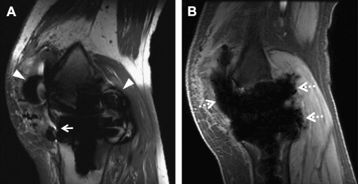
When a clinical magnet is appropriately shimmed, the B 0 field is typically homogeneous over a 45-cm diameter to at least 1.5 ppm. In the setting of orthopedic implants, the static magnetic field becomes inhomogeneous, typically because of magnetic susceptibility but also influenced by implant size, shape, and orientation. These inhomogeneities cause 3 main types of artifacts on conventional, clinical MR images: T2* dephasing, displacement artifacts, and failure of fat suppression ( Fig. 1 A ). These artifacts are described in further detail later, and conventional techniques used to decrease these artifacts are summarized in Table 2 .
| Technique | Trade-off |
|---|---|
| Use a lower field strength magnet | Higher tesla magnets may have more powerful gradients Lower SNR |
| Avoid conventional gradient sequences | Gradient sequences are often faster than other sequences and allow a lower echo time |
| Decrease slick thickness | Lower SNR Increased time to cover same volume |
| Increase matrix | Lower SNR Increased time |
| Increase receiver bandwidth | Lower SNR |
| Decrease TE | Alters contrast, may decrease visualization of fluid/edema |
| Increasing echo train length | T2 blurring |
| Swap phase-frequency directions to improve visualization of an obscured area | May result in increased imaging time to avoid wrap Vascular pulsation artifacts along phase direction may obscure anatomy |
| Use of inversion recovery for fat suppression | Lower SNR |
| Use of Dixon techniques for fat suppression | Increased time Fat-water swapping artifact |
| Precontrast and postcontrast subtraction images | Lower SNR Misregistration can cause false-positive enhancement |
T2* dephasing
T2* dephasing occurs because of varying rates of precession inside a voxel (see Fig. 1 B). Dephasing effects can be minimized through the use of refocusing pulses, such as those used with spin-echo or fast spin-echo (FSE) imaging. T2* dephasing can also be minimized with decreasing effective echo time (TE), such as with ultrashort TE (UTE) techniques ( Fig. 2 ).

Displacement artifacts
Displacement artifacts arise because of frequency variations in both the slice selection (through-plane, z-axis) and readout (in-plane, x-y–axis) directions. In clinical MR imaging, spatial variation of frequency is tightly controlled through the use of gradients. Alterations of this frequency because of susceptibility cause mismapping of signal with mild cases showing geometric distortion and severe cases showing signal loss in 1 region and pile-up artifact in another.
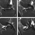
Displacement artifacts can be reduced by using stronger imaging gradients. This factor allows for inclusion of more frequencies within the same voxel, and therefore spreads the metal artifact effects over fewer voxels and a smaller portion of the anatomy. Slice selection gradient strength is increased by selecting a smaller slice thickness. Readout gradient strength is increased by increasing the number of frequencies per pixel (readout bandwidth). Pseudocylindrical structures such as screws often show an arrow (or cloverleaf) artifact pattern, with the direction of the arrow pointing in the frequency encode direction ( Fig. 3 A ). Generally, swapping the phase-frequency encode directions does not alter the overall degree of metal artifact, but this can allow visualization of otherwise obscured anatomy. However, in some scenarios, empirical evidence suggests that the overall degree of artifact is reduced. For instance, on axial images in patients with TKRs, choosing a left-right frequency encoding direction minimizes artifact surrounding the femoral component.

Alignment of the main magnetic field, long axis of the magnetic object, and frequency encode direction results in optimal reduction of metallic artifacts. This situation explains the decreased susceptibility seen with knee arthroplasty pegs/stems and intramedullary rods compared with interlocking screws, which are orthogonal to B 0 , or with complex geometric shapes such as the femoral component of a TKR.
Phase encoding, in contrast to frequency encoding, is resistant to displacement artifacts. Conventional two-dimensional (2D) sequences phase encode in 1 direction, whereas three-dimensional (3D) sequences phase encode in 2 directions (through-plane and 1 in-plane direction). However, with most recent 3D FSE sequences including CUBE (GE Medical Systems, Milwaukee, WI), SPACE (Siemens, Erlangen, Germany), and VISTA (Philips, Eindhoven, Netherlands), there is thick slab-selective excitation, and through-plane signal distortion is large, despite phase encoding (see Fig. 3 B). Displacement artifacts can be minimized with thin slabs at the expense of imaging time. Nonselective 3D imaging would also circumvent these effects, but the entire z-axis direction would have to be imaged to avoid aliasing.
Failure of fat suppression
Failure of fat suppression occurs most dramatically with the use of spectrally selective or chemical fat suppression. Chemical fat suppression relies on the chemical shift difference between the water peak and main fat peak, which is approximately 3.5 ppm (∼220 Hz at 1.5 T and ∼440 Hz at 3 T, with fat precessing slower than water). As a preparatory pulse, the fat is selectively excited based on expected precession frequency, and the signal is crushed before application of a standard imaging sequence. In the setting of metal, artifactual frequency shift can easily cause complete failure of fat suppression and in some areas can cause saturation of the water peak (see Fig. 1 A).
Inversion recovery techniques such as short tau inversion recovery (STIR) are more resistant to B 0 inhomogeneities, because fat is nulled based on the short T1 time relative to water. However, STIR can have several disadvantages. The inversion pulse also affects water with resultant decreased signal-to-noise ratio (SNR) by approximately 40% to 50%. Because of the bandwidth mismatch between the inversion and excitation-refocusing pulses, standard STIR sequences can show distortion artifacts, which obscure surrounding anatomic structures as well as cause inefficient fat suppression. Use of an optimized higher bandwidth inversion pulse has been shown to decrease these artifacts.
In addition, STIR should not be used with exogenous contrast, because enhancing tissue may also be nulled by the inversion pulse. In the setting of contrast administration, subtraction images between non–fat-suppressed T1-weighted precontrast and postcontrast images can be helpful, assuming identical imaging parameters and no patient motion. Even with no appreciable motion between source images, the radiologist should carefully scrutinize edge enhancement on subtraction images, which may be artifactual because of minimal misregistration. Simple subtraction of MR images causes a decrease in SNR, but in our experience, aggressive windowing and leveling can readily show regions of enhancement.
Chemical shift-based fat suppression methods (commonly known as Dixon techniques) rely on phase shifts created by the differences in resonance frequency of fat and water. Many variations of this technique have been used since the initial description. Although Dixon techniques provide for robust fat suppression, they are limited, because of longer scan times. In addition, there is a fundamental ambiguity in distinguishing between fat and water when 1 molecule dominates intravoxel signal. Complex algorithms have been used to resolve this, but most assume a smoothly varying B 0 field, which may not be the case in the presence of metal. Iterative decomposition of water and fat with echo asymmetry and least squares estimation (IDEAL) is a multipoint water–fat separation method, which has been described to be useful in the setting of smaller metal artifact. Typically IDEAL should not be used for larger implants, but in some instances, it can be helpful (see Fig. 1 B).
Advanced metal artifact reduction techniques
View Angle Tilting
View angle tilting (VAT) is a technique used to reduce in-plane displacement artifacts, originally introduced in 1988 by Cho and colleagues. VAT relies on the fact that magnetic susceptibility artifacts cause displacements in both slice selection and readout directions. By viewing the slice from an angle, these displacements can be made to cancel each other ( Fig. 4 ). This situation is accomplished by reapplying the slice selection gradient during the readout period. The metal artifact reduction sequence (MARS) has been described as a specific technique that uses the VAT method in conjunction with stronger slice selection gradients and readout bandwidths to further reduce distortions. However, with these techniques, through-plane distortions are not corrected, and small blurring artifacts can be seen. MARS is now commonly used to refer to all artifact reducing techniques.

Slice Encoding for Metal Artifact Correction
Slice encoding for metal artifact correction (SEMAC) uses the VAT-compensation gradient to suppress in-plane displacements but also adds additional phase encoding steps in the slice selection direction to correct through-plane displacements. An FSE sequence is used to avoid dephasing artifacts. SEMAC is slice selective (2D excitations), but image acquisition is 3D. Early versions of SEMAC used 16 through-plane phase encode steps, which could register off-resonance contributions of up to ±16 kHz ( Fig. 5 ). The number of through-plane phase encoding steps is limited to save time and encodes subvolumes centered on the excited slice volumes. Phase encoding rather than slice selection resolves the position in the slice direction, and slice selection thickness does not affect the final through-slice resolution. Largely because of the extra phase encode steps, SEMAC can be time consuming, and multiple acceleration techniques have been used, including parallel imaging and partial Fourier reconstruction. In addition, to achieve 5-minute to 6-minute scan times per sequence, the number of through-plane phase encode steps has been reduced to 8 to 12 when imaging after TKR. Significant residual artifacts are seen with the decrease in number of phase encode steps, particularly adjacent to implants with higher susceptibility such as cobalt-chromium-molybdenum alloys (>80 kHz off-resonance at 1.5 T) or steel (>192 kHz at 1.5 T) ( Fig. 6 ). On the Siemens platform, SEMAC combined with increased readout and radiofrequency pulse bandwidths is termed WARP-Turbo Spin Echo (Siemens, Erlangen, Germany). On the Philips platform (Philips, Eindhoven, Netherlands), SEMAC with decreased phase encode steps has been combined with off-resonance suppression (different radiofrequency bandwidths for excitation and refocusing pulses) to achieve faster imaging times.

Multiacquisition Variable-Resonance Image Combination
Multiacquisition variable-resonance image combination (MAVRIC) is a technique described by Koch and colleagues in 2009. MAVRIC uses limited bandwidth frequency selective excitation to suppress in-plane displacements. Narrow spectral bandwidth imaging is performed for the on-resonance frequency and repeated for multiple partially overlapping offset frequencies, each regarded as individual spectral bins ( Fig. 7 ). Spectral bins closer to the on-resonance frequency image farther away from the implant, whereas off-resonance bins image closer to the implant. After excitation, a standard 3D-FSE sequence is used for acquisition. Phase encoding is used to resolve displacements in the through-plane direction, and the refocusing pulse avoids dephasing artifacts ( Fig. 8 ). Similar to SEMAC data, MAVRIC spectral bin subimages are combined through quadrature summation (sum of squares) to form a composite image. The total number of spectral bins affects imaging time, and typically, bins with 2.25 kHz full width at half maximum and 1 kHz bin separation are used. Coverage of a range of ±12 kHz off-resonance has been described for use with clinically compatible imaging times. However, by limiting the number of off-resonance spectral bins to save time, tissue immediately adjacent to higher susceptibility implants is not excited or imaged and is represented by regions of signal void. Another potential limitation of MAVRIC is aliasing in the through-plane direction because of nonselective volume excitation, although this is generally more problematic in hip or shoulder imaging and less so when imaging the knee.
Current Generation Hybrid Techniques
More recently, the similarities between the multispectral imaging approaches of SEMAC and MAVRIC were highlighted by Koch and colleagues, who introduced the MAVRIC-SEMAC hybrid technique. This technique adds a through-plane gradient to the multiple spectral acquisitions of MAVRIC. This gradient is applied during excitation, thereby adding slice selectivity, and during readout, thereby adding VAT. Additional phase encoding steps in the through-plane direction are also performed, similar to SEMAC. This hybrid approach was originally termed volume-selective 3D multispectral imaging (VS-3D-MSI), but has now been productized as MAVRIC SeLective on the GE platform. Similar approaches have been described on other vendor platforms, such as multiple slab acquisition with VAT based on a SPACE sequence (MSVAT-SPACE) on the Siemens platform. Advances to the techniques listed earlier are rapidly progressing, in particular in combination with acceleration methods, such as parallel imaging and compressed sensing.
UTE-MAVRIC
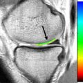
UTE techniques use TEs in the order of microseconds, which allow for rapid encoding of the signal before decay. Compared with conventional TEs, in which short T2/T2* structures are hypointense, musculoskeletal tissues such as ligaments, tendons, and cortical bone are directly visible with UTE. In addition, use of UTE sequences can allow direct visualization of solid polymers such as the polyethylene spacer of implants.
UTE-MAVRIC combines UTEs with the multispectral approach of the MAVRIC sequence to minimize intravoxel dephasing and excite/image spins closer to the implant, which would have otherwise been excluded ( Fig. 9 ). Unlike other imaging techniques, UTE-MAVRIC generates 3D images with isotropic voxels, which allows reconstruction into any imaging plane after acquisition. Imaging time with UTE-MAVRIC is optimized through undersampling of the off-resonance bins. If the composition of the particular metal implant is known, the examination can be further tailored by increasing or decreasing the number of off-resonance bins. For instance, more bins should be used with higher susceptibility implants such as cobalt-chrome (see Fig. 9 A) compared with titanium (see Fig. 9 C).
Related posts:
 MR Imaging of the Knee
 Magnetic Resonance Imaging of the Meniscus
 Magnetic Resonance Imaging of the Postoperative Meniscus
 Magnetic Resonance Imaging of Cartilage Repair Procedures
MR Imaging Assessment of Arthritis of the Knee
Magnetic Resonance Imaging of Cartilage Repair Procedures
MR Imaging Assessment of Arthritis of the Knee
 Quantitative Magnetic Resonance Imaging of the Articular Cartilage of the Knee Joint
Stay updated, free articles. Join our Telegram channel

Full access? Get Clinical Tree


