Interactions of Ionizing Radiation
When an x- or γ-ray beam passes through a medium, interaction between photons and matter can take place with the result that energy is transferred to the medium. The initial step in the energy transfer involves the ejection of electrons from the atoms of the absorbing medium. These high-speed electrons transfer their energy by producing ionization and excitation of the atoms along their paths. If the absorbing medium consists of body tissues, sufficient energy may be deposited within the cells, destroying their reproductive capacity. However, most of the absorbed energy is converted into heat, producing no biologic effect.
5.1. Ionization
The process by which a neutral atom acquires a positive or a negative charge is known as ionization. Removal of an orbital electron leaves the atom positively charged, resulting in an ion pair. The stripped electron, in this case, is the negative ion and the residual atom is the positive ion. In some cases, an electron may be acquired by a neutral atom and the negatively charged atom then becomes the negative ion.
Charged particles such as electrons, protons, and α particles are known as directly ionizing radiation provided they have sufficient kinetic energy to produce ionization by collision1 as they penetrate matter. The energy of the incident particle is lost in a large number of small increments along the ionization track in the medium, with an occasional interaction in which the ejected electron receives sufficient energy to produce a secondary track of its own, known as a δ ray. If, on the other hand, the energy lost by the incident particle is not sufficient to eject an electron from the atom but is used to raise the electrons to higher-energy levels, the process is termed excitation.
The uncharged particles such as neutrons and photons are indirectly ionizing radiation because they liberate directly ionizing particles from matter when they interact with matter. Ionizing photons interact with the atoms of a material or absorber to produce high-speed electrons by three major processes: photoelectric effect, Compton effect, and pair production. Before considering each process in detail, we shall discuss the mathematical aspects of radiation absorption.
5.2. Photon Beam Description
An x-ray beam emitted from a target or a γ-ray beam emitted from a radioactive source consists of a large number of photons, usually with a variety of energies. A beam of photons can be described by many terms, some of which are defined as follows:
The fluence (Φ) of photons is the quotient dN by da, where dN is the number of photons that enter an imaginary sphere of cross-sectional area da.

Fluence rate or flux density (φ) is the fluence per unit time.

where dt is the time interval.
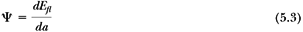
Energy fluence (ψ) is the quotient of dEfl by da, where dEfl is the sum of the energies of all the photons that enter a sphere of cross-sectional area da.
For a monoenergetic beam, dEfl is just the number of photons dN times energy hn carried by each photon:

Energy fluence rate, energy flux density, or intensity (c) is the energy fluence per unit time:

5.3. Photon Beam Attenuation
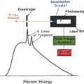
An experimental arrangement designed to measure the attenuation characteristics of a photon beam is shown in Figure 5.1. A narrow beam of monoenergetic photons is incident on an absorber of variable thickness. A detector is placed at a fixed distance from the source and sufficiently farther away from the absorber so that only the primary photons (those photons that passed through the absorber without interacting) are measured by the detector. Any photon scattered by the absorber is not supposed to be measured in this arrangement. Thus, if a photon interacts with an atom, it is either completely absorbed or scattered away from the detector.
Under these conditions, the reduction in the number of photons (dN) is proportional to the number of incident photons (N) and to the thickness of the absorber (dx). Mathematically:
or
where μ is the constant of proportionality, called the attenuation coefficient. The minus sign indicates that the number of photons decreases as the absorber thickness increases. The above equation can also be written in terms of intensity (I):
or
If thickness x is expressed as a length, then μ is called the linear attenuation coefficient. For example, if the thickness is measured in centimeters, the units of μ are 1/cm, or cm-1.
Equation 5.7 is identical to Equation 2.1, which describes radioactive decay, and μ is analogous to decay constant λ. As before, the differential equation for attenuation can be solved to yield the following equation:
where I(x) is the intensity transmitted by a thickness x and I0 is the intensity incident on the absorber. If I(x) is plotted as a function of x for a narrow monoenergetic beam, a straight line will be obtained on semilogarithmic paper (Fig. 5.2A), showing that the attenuation of a monoenergetic beam is described by an exponential function.
The term analogous to half-life (section 2.4) is the half-value layer (HVL) defined as the thickness of an absorber required to attenuate the intensity of the beam to half its original value.
That means that when x = HVL, I/I0 = 1/2, by definition. Thus, from Equation 5.8 it can be shown that:
That means that when x = HVL, I/I0 = 1/2, by definition. Thus, from Equation 5.8 it can be shown that:
 Figure 5.1. Diagram to illustrate an experimental arrangement for studying narrow-beam attenuation through an absorber. Measurements are under “good geometry” (i.e., scattered photons are not measured). |
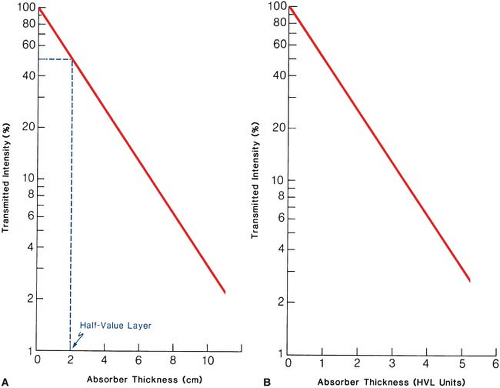 Figure 5.2. A: Graph showing percent transmission of a narrow monoenergetic photon beam as a function of absorber thickness. For this quality beam and absorber material, HVL = 2 cm and μ = 0.347 cm-1. B: Universal attenuation curve showing percent transmission of a narrow monoenergetic beam as a function of absorber thickness in units of half-value layer (HVL). |
As mentioned previously, exponential attenuation strictly applies to a monoenergetic beam. Figure 5.2B is a general attenuation curve for a monoenergetic beam or a beam whose half-value layer does not change with absorber thickness. Such a curve may be used to calculate the number of HVLs required to reduce the transmitted intensity to a given percentage of the incident intensity.
A practical beam produced by an x-ray generator, however, consists of a spectrum of photon energies. Attenuation of such a beam is no longer quite exponential. This effect is seen in Figure 5.3, in which the plot of transmitted intensity on semilogarithmic paper is not a straight line. The slope of the attenuation curve decreases with increasing absorber thickness because the absorber or filter preferentially removes the lower-energy photons. As shown in Figure 5.3, the first HVL is defined as that thickness of material which reduces the incident beam intensity by 50%. The second HVL reduces the beam to 50% of its intensity after it has been transmitted through the first HVL. Similarly, the third HVL represents the quality of the beam after it has been transmitted through the absorber of thickness equal to two HVLs. In general, for a heterogeneous beam, the first HVL is less than the subsequent HVLs. As the filter thickness increases, the average energy of the transmitted beam increases or the beam becomes increasingly harder. Thus, by increasing the filtration in such an x-ray beam, one increases the penetrating power or the half-value layer of the beam.
5.4. Coefficients
A. Attenuation Coefficient
In the previous section, we discussed the linear attenuation coefficient μ, which has units of cm-1. In general, this coefficient depends on the energy of the photons and the nature of the material.
Since the attenuation produced by a thickness x depends on the number of electrons presented in that thickness, μ depends on the density of the material. Thus, by dividing μ by density r, the resulting coefficient (μ/r) will be independent of density; μ/r is known as the mass attenuation coefficient. This is a more fundamental coefficient than the linear coefficient, since the density has been factored out and its dependence on the nature of the material does not involve density but rather the atomic composition.
Since the attenuation produced by a thickness x depends on the number of electrons presented in that thickness, μ depends on the density of the material. Thus, by dividing μ by density r, the resulting coefficient (μ/r) will be independent of density; μ/r is known as the mass attenuation coefficient. This is a more fundamental coefficient than the linear coefficient, since the density has been factored out and its dependence on the nature of the material does not involve density but rather the atomic composition.
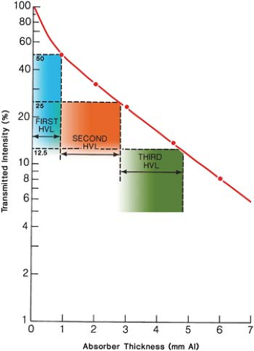 Figure 5.3. Schematic graph showing transmission of an x-ray beam with a spectrum of photon energies through an aluminum absorber. First half-value layer (HVL) = 0.99 mm Al, second HVL = 1.9 mm Al, and third HVL = 2.0 mm Al. |
The mass attenuation coefficient has units of cm2/g because μ/r = cm-1/(g/cm3). When using μ/r in the attenuation Equation 5.8, the thickness should be expressed as rx, which has units of g/cm2, because μx = (μ/r)(rx) and rx = (g/cm3)(cm).
In addition to the cm and g/cm2 units, the absorber thickness can also be expressed in units of electrons/cm2 and atoms/cm2. The corresponding coefficients for the last two units are electronic attenuation coefficient (eμ) and atomic attenuation coefficient (aμ), respectively:
where Z is the atomic number and N0 is the number of electrons per gram and N0 is given by:
The attenuation process or the attenuation coefficient represents the fraction of photons removed per unit thickness. The transmitted intensity I(x) in Equation 5.8 is caused by photons that did not interact with the material. Those photons that produced interactions will transfer part of their energy to the material and result in part or all of that energy being absorbed.
B. Energy Transfer Coefficient
When a photon interacts with the electrons in the material, a part or all of its energy is converted into kinetic energy of electrons. If only a part of the photon energy is given to the electron, the photon itself is scattered with reduced energy. The scattered photon may interact again with a partial or complete transfer of energy to the electrons. Thus, a photon may experience one or multiple interactions in which the energy lost by the photon is converted into kinetic energy of electrons.
If we consider a photon beam traversing a material, the fraction of photon energy transferred into kinetic energy of charged particles per unit thickness of absorber is given by the energy transfer coefficient (μtr). This coefficient is related to μ as follows:
where  is the average energy transferred into kinetic energy of charged particles per interaction. The mass energy transfer coefficient is given by μtr/r. is the average energy transferred into kinetic energy of charged particles per interaction. The mass energy transfer coefficient is given by μtr/r. |
C. Energy Absorption Coefficient
Most of the electrons set in motion by the photons will lose their energy by inelastic collisions (ionization and excitation) with atomic electrons of the material. A few, depending on the atomic number of the material, will lose energy by bremsstrahlung interactions with the nuclei. The bremsstrahlung energy is radiated out of the local volume as x-rays and is not included in the calculation of locally absorbed energy.
The energy absorption coefficient (μen) is defined as the product of energy transfer coefficient and (1 – γ) where g is the fraction of the energy of secondary charged particles that is lost to bremsstrahlung in the material.
As before, the mass energy absorption coefficient is given by μen/r.
For most interactions involving soft tissues or other low-Z material in which electrons lose energy almost entirely by ionization collisions, the bremsstrahlung component is negligible. Thus, μen = μtr under those conditions. These coefficients can differ appreciably when the kinetic energies of the secondary particles are high and material traversed has a high atomic number. The energy absorption coefficient is an important quantity in radiotherapy since it allows the evaluation of energy absorbed in the tissues, a quantity of interest in predicting the biologic effects of radiation.
5.5. Interactions of Photons with Matter
Attenuation of a photon beam by an absorbing material is caused by five major types of interactions. One of these, photodisintegration, was considered in section 2.8F. This reaction between photon and nucleus is only important at very high photon energies (>10 MeV). The other four processes are coherent scattering, the photoelectric effect, the Compton effect, and the pair production. Each of these processes can be represented by its own attenuation coefficient, which varies in its particular way with the energy of the photon and with the atomic number of the absorbing material. The total attenuation coefficient is the sum of individual coefficients for these processes:
where σcoh, t, σc, and p are attenuation coefficients for coherent scattering, photoelectric effect, Compton effect, and pair production, respectively.
5.6. Coherent Scattering
The coherent scattering, also known as classical scattering or Rayleigh scattering, is illustrated in Figure 5.4. The process can be visualized by considering the wave nature of electromagnetic radiation.
This interaction consists of an electromagnetic wave passing near the electron and setting it into oscillation. The oscillating electron reradiates the energy at the same frequency as the incident electromagnetic wave. These scattered x-rays have the same wavelength as the incident beam. Thus, no energy is changed into electronic motion and no energy is absorbed in the medium. The only effect is the scattering of the photon at small angles. The coherent scattering is probable in high-atomic-number materials and with photons of low energy. The process is only of academic interest in radiation therapy.
This interaction consists of an electromagnetic wave passing near the electron and setting it into oscillation. The oscillating electron reradiates the energy at the same frequency as the incident electromagnetic wave. These scattered x-rays have the same wavelength as the incident beam. Thus, no energy is changed into electronic motion and no energy is absorbed in the medium. The only effect is the scattering of the photon at small angles. The coherent scattering is probable in high-atomic-number materials and with photons of low energy. The process is only of academic interest in radiation therapy.
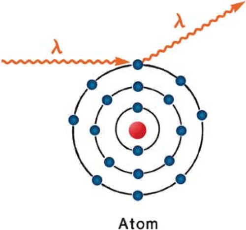 Figure 5.4. Diagram illustrating the process of coherent scattering. The scattered photon has the same wavelength as the incident photon. No energy is transferred. |
 Figure 5.5. Illustration of the photoelectric effect. |
5.7. Photoelectric Effect
The photoelectric effect is a phenomenon in which a photon interacts with an atom and ejects one of the orbital electrons from the atom (Fig. 5.5). In this process, the entire energy (hn) of the photon is first absorbed by the atom and then transferred to the atomic electron. The kinetic energy of the ejected electron (called the photoelectron) is equal to hn – EB, where EB is the binding energy of the electron. Interactions of this type can take place with electrons in the K, L, M, or N shells.
Related posts:

Stay updated, free articles. Join our Telegram channel

Full access? Get Clinical Tree


