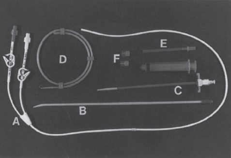
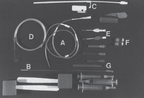
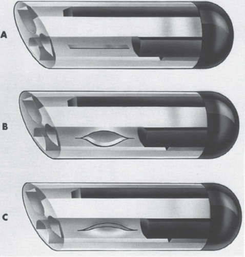
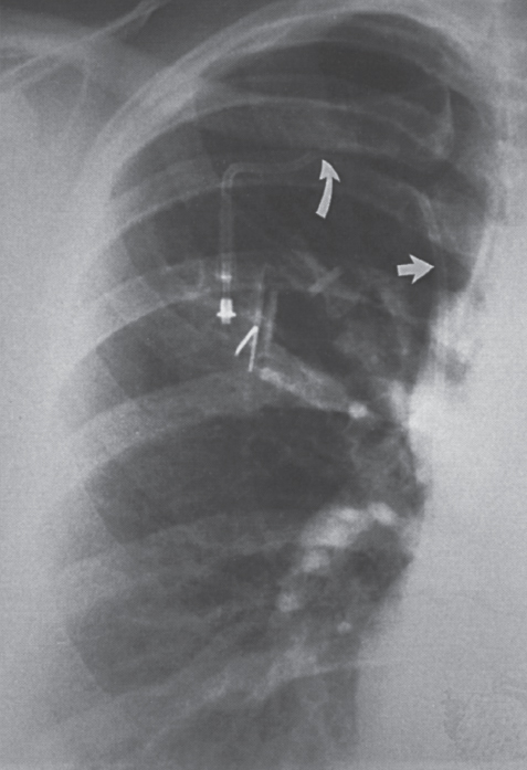
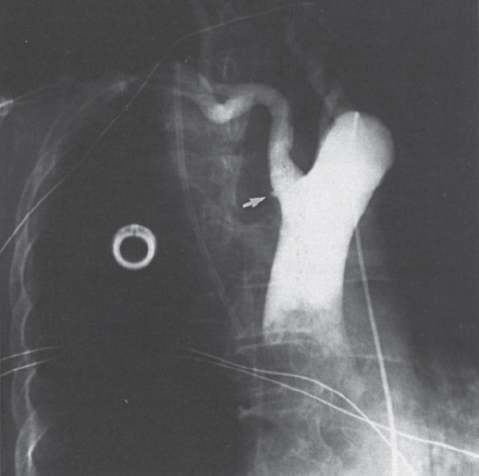
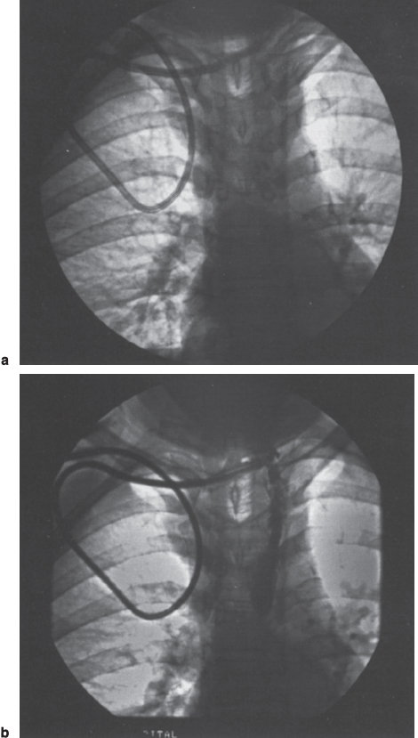
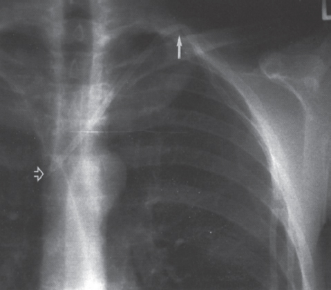
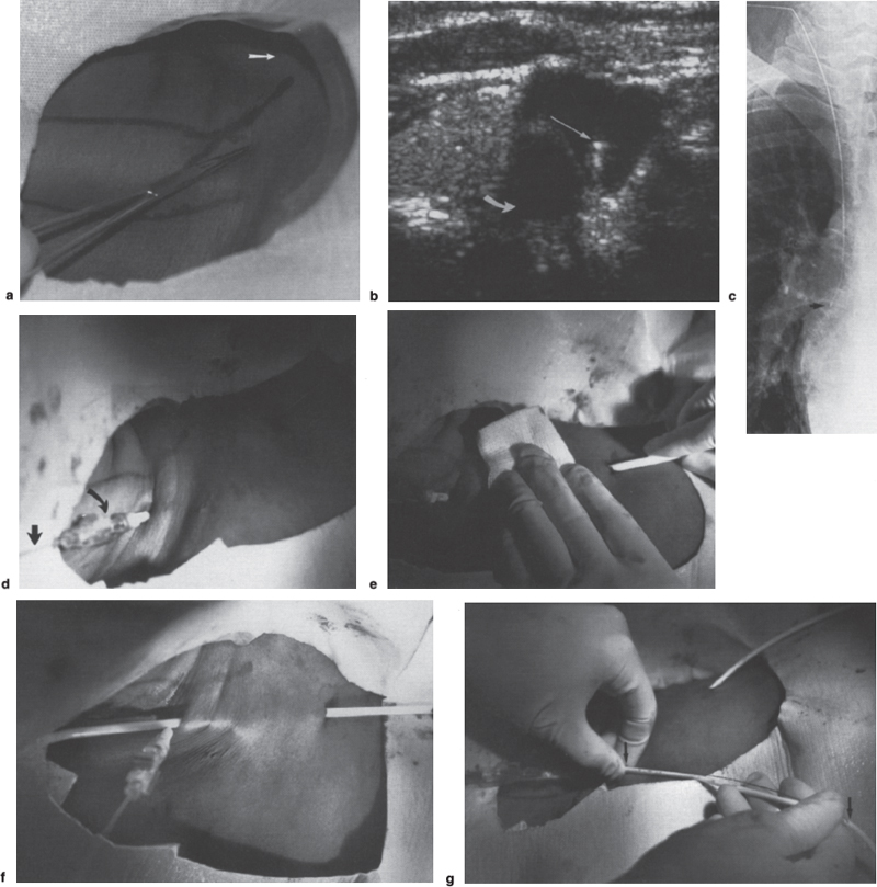
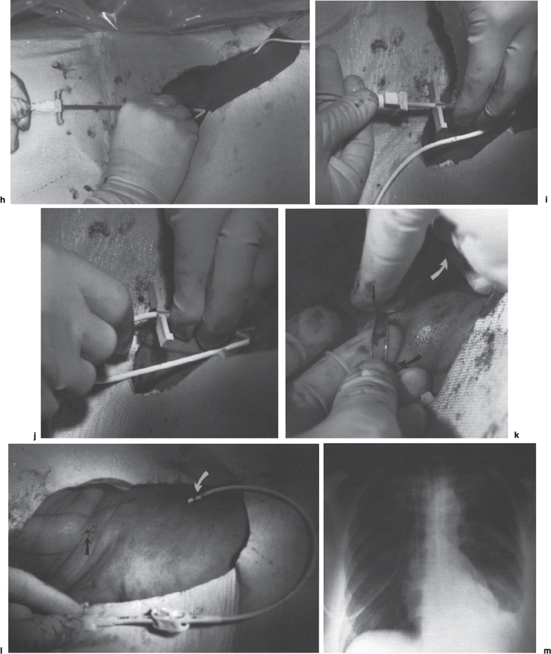
Interventional Radiologic Placement and Management of Infusion Catheters Since the introduction of the Broviac catheter in 19731 and the subsequent introduction of the Hickman catheter2 in 1979, chronic infusion catheters have played an increasing role in a wide variety of patient-care situations, including the administration of chemotherapy, long-term antibiotics, and both in-hospital and home nutritional support. It is estimated that about three million central venous catheters are placed in the United States each year.3 The most recent industry estimates indicate that approximately 140,000 tunneled infusion catheters will be placed in the United States in 1999, fewer than the 1994 prediction of 250,000 tunneled devices (Mark Foster, Mark Albrecht, Bard Access Systems, personal communication, 1994). This estimate likely reflects a shifting trend toward peripherally inserted central catheters (PICCs), of which about 850,000 are expected to be placed in 1999. Although tunneled infusion catheters and ports initially were placed in the operating room by surgeons, the past decade has seen a gradual transition from surgical placement to interventional radiologic placement of vascular access devices. This transition was supported by excellent early work in this field,4,5 which documented the efficacy and safety of the percutaneous approach in the interventional radiology suite. Subsequent studies confirmed that placement in the interventional radiology suite is safer, faster, and less expensive than surgical placement and that the infectious complications rate is no higher than that achieved in the operating room.6–11 This discussion concentrates on interventional radiologic placement of chronic infusion cathetprs. Most chronic infusion catheters are made of silicone rubber (Silastic) or polyurethane, although a variety of other catheter materials have been evaluated for this purpose. Silastic and polyurethane are used because they are relatively soft, durable, and biologically inert. Silastic has proved superior to more rigid materials such as polyvinyl chloride (PVC) in preventing thrombotic complications; one series of nontunneled catheters showed an 11.5% thrombosis rate with silicone compared with 46.1% with PVC.12 Tunneled catheters have a Dacron cuff that anchors the catheter in place through tissue ingrowth into the fibers of the cuff. Once incorporated, the cuff theoretically prevents infection by acting as a mechanical barrier and also prevents dislodgment of the catheter. The presence of an additional silver-impregnated collagen cuff (Vitaphore) in some catheters is intended to decrease the catheter-related infection further. Some data support13,14 and some contradict this contention, however, not only in regard to nontunneled catheters15,16 but also with tunneled infusion catheters.17 Additionally, its presence may interfere with the incorporation of an adjacent Dacron cuff into the subcutaneous tissues.18 Another approach to reducing infection is surface treatment of catheters. The benefit of coating or impregnation with silver-containing preparations in nontunneled catheters is unclear; there are data showing benefit19–20 or lack thereof.21,22 In tunneled catheters, at least one randomized study showed no benefit against catheter-related infection.23 Antibiotic-impregnated catheters significantly decrease the catheter-related infection rate; specifically, the combination of rifampin and minocycline appears most beneficial.24–27 In fact, a prospective, randomized clinical trial showed this combination to be superior to silver sulfadiazine-chlorhexidine impregnated catheters.28 None of these studies has examined the effect of antibiotic impregnation on tunneled catheters, however. Current tunneled catheters are available in a wide variety of sizes and as single- or multiple-lumen catheters. The Broviac catheter (Bard Access Systems, Salt Lake City, UT) is a small-bore, single-lumen catheter (2.7 to 6.6F) and is used in the pediatric population. This catheter is tapered so that the intravenous portion is small and the tunneled and external portions are larger and less susceptible to breakage (hence its use in children). Probably the most commonly used are single- and double-lumen Hickman (Fig. 24–1) and Groshong catheters (Bard Access Systems) (Fig. 24–2), which range from 9.6 to 19.2F; the larger diameters are used most commonly for hemodialysis and plasmapheresis. The Groshong catheter, introduced in the late 1980s, differs from the Hickman catheter (Bard Access Systems) in that the tip of the catheter has a self-sealing slitlike valve (Fig. 24–3), which facilitates catheter care by reducing the need for flushing29; however, catheter malfunction appears more often with the Groshong design, and its use might best be limited to those patients who are unable to manage daily flush regimen or those who cannot receive heparin.30,31 The concept of tunneled catheters has been challenged32 by the Hohn catheter, a nontunneled noncuffed Silastic catheter designed for in-hospital use. This catheter, which is less expensive to place and offers acceptable thrombotic and infectious complication rates, may be a viable alternative for inpatients. Radiologic placement of Hohn catheters has been described with excellent results; some patients in that series were sent home with the catheters.33 Yet another group of devices are the PICCs and the subcutaneous ports (discussed in Chapters 25 and 26, respectively). FIGURE 24–1. Hickman catheter. The components of the Hickman catheter insertion kit are as follows: (A) catheter, (B) plastic tunneler, (C) peel-away sheath, (D) short guidewire, (E) 18-gauge needle, and (F) catheter caps. Note that for radiologic placement of Hickman catheters, a 21-gauge needle generally is used rather than the needle included in the kit (see text). FIGURE 24–2. Groshong catheter. Contents of the Groshong catheter insertion kit are as follows: (A) catheter, (B) metal tunneler, (C) peel-away sheath and cutter, (D) short guidewire, (E) catheter hubs, (F) caps, and (G) 18-gauge needle. A 21-gauge needle usually is used for access rather than the needle provided in the kit. FIGURE 24–3. Diagram of Groshong catheter valve. Detail of the tip of a triple-lumen Groshong catheter is shown. (A) In the resting state, the slit is closed thereby preventing blood from entering the catheter lumen. (B) When material is infused into the catheter, the slit opens to allow infusion. (C) When blood is aspirated from the catheter, the valve also opens. Note that the catheter shown is a triple-lumen catheter. (Photo courtesy of Bard Access Systems; used with permission.) FIGURE 24–4. Catheter “pinch-off” occurring in a surgically placed subcutaneous port. Note the catheter fracture point (curved arrow). The distal catheter fragment (straight arrow) has migrated somewhat but has not embolized to the heart or lungs. Catheter “pinch-off” can be avoided by the more lateral placement technique used in interventional radiology (see text). The choice of which type of chronic venous access device will be used is based on patient preference, type of access needed [i.e., multidrug versus single drug, total parenteral nutrition (TPN)], available sites for venous access, and the preference of the operator and referring clinician. Familiarity with a variety of different devices will allow the greatest versatility. The indications for placement of a central venous access device have most commonly been the administration of chemotherapeutic agents and TPN because of the effects of these agents on peripheral veins and subsequent rapid depletion of peripheral venous access. Expanded indications include chronic antibiotic therapy, such as for osteomyelitis or subacute bacterial endocarditis, and repetitive administration of blood products. In the population infected with human immunodeficiency virus (HIV), the need for repeated venipuncture and administration of antibiotics makes chronic access often desirable. It should be emphasized that for certain well-circumscribed indications with defined endpoints, such as a 6-week course of antibiotics, a nontunneled device such as the Hohn catheter or a PICC may be a cost-effective alternative to Hickman catheter placement (see section on costs later). On the other hand, because infection rates increase with the use of TPN through Hohn catheters,33 if TPN is needed, a tunneled catheter or PICC may be a better option.34 Contraindications to tunneled catheter placement include active infection, particularly bacteremia. In patients in whom catheters are being placed for chronic antibiotic therapy, control of bacteremia with temporary catheters should be attempted before the tunneled device is placed. Coagulopathy and thrombocytopenia represent relative contraindications, because these patterns usually can be corrected. We prefer to have a platelet count in excess of 50,000 but have successfully placed catheters in patients with platelet counts as low as 25,000. Likewise, we prefer coagulopathy to be corrected before catheter placement and use an International Normalized Ratio (INR) of 1.5 or lower as a target value. Because a variety of imaging guidance procedures can be used for catheter placement (see later), elevated creatinine is not a contraindication. Traditionally, lack of available venous access has been a problem for surgical placement; however, with the advent of radiologic guidance, almost every patient has a usable vein. Alternatives to the traditional subclavian and jugular approach include the translumbar,35–38 transhepatic,36,39,40 and azygos41 routes (see Chapter 27). As noted, patient and referring physician preference may dictate the type of device used. In addition, patient considerations, such as the ability to care for an external catheter, should be weighed when deciding between the various available devices. Generally, the fewest lumens and the smallest catheter that will suit the patient’s needs should be used because complications (infectious and thrombotic) increase with size and lumen number.33,42 Single-drug therapy, such as for antibiotics, usually requires only one lumen, whereas TPN usually requires at least two lumens to keep one lumen dedicated for that purpose. As noted previously, if TPN is to be administered, tunneled catheters or PICCs are probably preferable to nontunneled devices, such as the Hohn catheter. Because many chemotherapeutic agents are incompatible with each other, oncology patients usually require a minimum of two lumens and often more. If more than two lumens are needed, a triple-lumen tunneled catheter is available, but in some instances, placement of two catheters may be preferable to allow larger lumens. If plasmapheresis is anticipated, the placement of a large-lumen pheresis/dialysis catheter is recommended as the flow rates are much better than those that can be achieved with a standard Hickman catheter. Once the appropriate device and route have been chosen, and the relevant laboratory data are in order, little other patient preparation is necessary. Our patients take nothing by mouth (NPO) for 6 hours before the procedure so that intravenous sedation with fentanyl and midazolam can be administered. Premedication with oral or intramuscular preparations is impractical in our clinical environment. Controversy exists in regard to antibiotic prophylaxis; some well-designed studies show no benefit43–47; however, data to the contrary also may be found.48,49 It is our practice not to use antibiotic prophylaxis; our catheter-related infection rate is low at 0.6 per 1000 catheter days. For vascular access placement, the interventional radiology suite is treated as an operating room. All personnel, including the patient, wear a cap and mask. Operator and assistant perform a full surgical scrub before gowning and gloving. Skin preparation can be performed with a povidone/iodine solution or chlorhexidine. We prefer the latter, which has been shown to be superior to povidone/iodine and alcohol in the prevention of catheter-related sepsis.50 Strict attention to sterile technique is imperative during all aspects of patient preparation and catheter placement. Using the approach described, multiple series describing interventional radiologic placement of ports and catheters have yielded infection rates the same as or less than those of surgical placement.4–11,46,47,51–55 There are no specific room requirements for Hickman catheter placement. Very little fluoroscopic guidance is necessary, and this can easily be accomplished with a C-arm. Therefore, virtually any fluoroscopic suite can be used for device placement as long as the appropriate sterility can be maintained. Traditionally, vascular access devices were placed either by cut-down or percutaneous access using landmarks. For subclavian access, this approach typically results in entering the subclavian vein relatively medially. In addition to the risks of arterial puncture and pneumothorax inherent with this blind approach, catheter entry between the first rib and clavicle can result in the so-called pinch-off syndrome,56–58 which is due to catheter entrapment between the costoclavicular ligament and the subclavius muscle59 and eventually may result in catheter fracture (Fig. 24–4), and embolization. Complication rates associated with blind percutaneous puncture range from 1 to 7%5,8,11,60–62 and include pneumothorax, arterial puncture, nerve injury, arteriovenous fistula, and catheter malposition (Figs. 24–5, 24–6, and 24–7). More importantly, the higher incidence of subclavian vein stenosis and thrombosis compared with the internal jugular vein (IJV) access has been shown in dialysis patients63–70 and others, including those suffering from neoplasms.71,72 The disadvantages of the cut-down technique are obvious, and the superiority of the percutaneous approach has been documented.62 Imaging guidance has been shown to be superior to the blind technique5,11,60,73–80 and is characterized by a 0 to 2% overall complication rate. The right IJV is the primary access site, owing to its relatively straight course down the superior vena cava (SVC). The patency rate is lower using the left-sided approach (IJV or subclavian vein).66,67,81–85 It should be noted, however, that the location of the catheter tip in those patients is often suboptimal, that is, in the proximal SVC or at the junction of the left innominate vein and SVC. Our clinical experience has found no statistically significant difference in dialysis catheter flow rates when tunneled left and right IJV catheters with their tip at the caval atrial junction or proximal right atrium were compared (Namyslowski et al, 1999, unpublished data). Although we have not evaluated this specifically, these data likely apply to chronic infusion catheters as well. Therefore, we resort to the left IJV access if the right is occluded. We use sonographic and fluoroscopic guidance when placing central venous catheters. Venography is used only in those patients who have venous occlusion and require a better definition of vascular anatomy to traverse the area successfully or to be able to choose an alternate access site. FIGURE 24–5. Arterial puncture occurring during surgical placement of a subcutaneous infusion port. Multiple attempts were made in the operating room at subclavian venous access. It was noted on fluoroscopy that the guidewire approached or crossed the midline on several attempts. Subclavian attempts were abandoned in favor of a right internal jugular approach. Postplacement radiograph demonstrated marked widening in the mediastinum, and the patient was referred to interventional radiology for arteriography. This right anterior oblique projection of an arch aortogram demonstrates a focal pseudoaneurysm of the innominate artery (arrow), which most likely occurred during the surgical attempts at subclavian vein catheterization. Although this is an unusual arterial puncture, punctures of the subclavian arteries are common with nonimaging guided approaches. FIGURE 24–6. Mediastinal Hickman catheter placement. Shortly after surgical placement of a right subclavian dual-lumen Hickman catheter, the patient was referred to interventional radiology to evaluate an unusual catheter position on the postplacement chest radiograph. Initial scout film (a) shows the unusual course of catheter extending across the midline to the left, in a position too high to be in a left innominate vein. Such a catheter position should prompt further evaluation. (b) Contrast injection of the catheter shows extravasation into the mediastinum. FIGURE 24–7. Catheter kinking and tip malposition. Chest radiograph obtained after surgical placement of a left internal jugular hemodialysis catheter demonstrates a kink in the catheter at or near the vein entrance site (arrow). Kinking such as shown here will result in unacceptably low or absent flow rates at hemodialysis. In addition, the tip of this catheter abuts the wall of the superior vena cava, which has been shown to be dangerous position (open arrow). Use of the catheter in this position can result in perforation, hemothorax, and death. To remedy this situation, this catheter should be advanced farther. Creating the subcutaneous tunnel with as gentle a curve as possible will help prevent kinking. For the initial venous entry, we use a 21-gauge fine-needle access system (Micropuncture, Cook, Blooming-ton, IN). We believe that fine-needle access further decreases puncture site complications. Most pneumothoraces occurring from 21-gauge puncture resolve spontaneously or can be treated with small-bore chest tube.8 Likewise, inadvertent arterial puncture is usually inconsequential when using a 21-gauge needle. Besides the fine-needle access set, virtually all other equipment needed to place the catheter is provided in the catheter kit (Figs. 24–1 and 24–2). The basic components of the kit are the catheter, peelaway sheath, and tunneling device. The guidewire provided in the catheter kit is usually sufficient, although occasionally a slightly stiffer guidewire may be needed. Depending on the size of catheter being placed, we may use serial dilators. For IJV access, the initial vascular entry site is chosen just above the clavicle, allowing enough room to accommodate a sterilely draped ultrasound probe. A transverse skin incision of 1 cm is made in the region overlying the IJV as localized with ultrasound, which generally corresponds to the location between the sternal and clavicular heads of the sternocleidomastoid muscle (Fig. 24–8a) and reflects the so-called middle approach with the landmark technique. The location of the IJV may vary, however, in up to 5.5% of patients.86 Precise vein localization and determination of its patency before needle placement underscores another advantage of ultrasound-guided venous access. The needle tip is followed by the ultrasound probe, usually 7 or 9 MHz, from the cutaneous incision to the venous entry. Indentation of the anterior wall of the IJV is seen, and the vein is then gently “popped” to gain access (Fig. 24–8b). Cooperative patients may facilitate this step by performing a Valsalva maneuver. Double-wall puncture without an intervening blood return may occur despite this technique, although it is perhaps more likely to be encountered in patients who are dehydrated, uncooperative, or have a small IJV. Unless promptly recognized and the needle pulled back, any further needle advancement may result in pneumothorax. It also should be recognized that a subclavian or common carotid artery may be located directly posterior to the IJV access site just above the clavicle. Double-wall puncture and further needle advancement undoubtedly will result in an arterial access. If recognized at the time of needle placement, the venous entry may be regained on pullback and, following a brief compression, the procedure is continued without interruption. Placement of 0.018-inch guidewire with its tip in the right atrium is an additional measure that will help to recognize an inadvertent arterial access. Once the guidewire is in place, a 4F coaxial dilator from the micropuncture set is inserted, and the patient is asked to take a deep breath in and hold it. The wire tip then is positioned at the level of the proximal right atrium, and its trailing segment is bent at the dilator hub (Fig. 24–8C). The patient then is allowed to breathe normally. The 0.018-inch guidewire and the inner dilator are removed and replaced with 0.035-inch J-shaped guidewire from the catheter kit. The 0.018-inch guidewire is set aside for future use (see later), and the 0.035-inch guide wire is inserted into the right atrium. A flow switch is advanced over the wire, Luer-locked to the 4F dilator, and locked on the wire. Then the subcutaneous tunnel is created. We have found that medial, parasternal tunneling minimizes upward displacement of catheter tip, which frequently occurs in women and obese patients.46 Lateral tunneling may be appropriate in others or in a situation where medial approach is not possible. An approximately 10-cm-long tunnel is created. For medial tunneling, the infraclavicular, parasternal skin entry site is anesthetized and an incision large enough to accommodate the catheter is made. The anticipated subcutaneous tract is infiltrated further with lidocaine using the 21-gauge venous access needle (Fig. 24–8d). The tunneling device then is advanced from the infraclavicular entry site to the cervical incision site. Care should taken to avoid skin puckering, which may occur if tunneling is too superficial. Countertraction applied to the skin with a dry gauze, while the tunneler is being advanced, often facilitates tunnel creation (Fig. 24–8e,f). Occasionally, difficulty may be encountered when advancing the tunneler through the cervical incision, often indicating that the tunneler is in a wrong tissue plane. In this case, it may be helpful to pull the tunneler back 1 to 2 cm and redirect it. Other maneuvers may include advancing the tip of the tunneler just cephalad to the cervical incision and then bringing it back while using the index finger to help “deliver the tip” into the incision or careful, sharp dissection with a no. 11 scalpel blade of the tissues “tented” by the tunneler tip in the supraclavicular incision. With the tunneler in place, the catheter is attached to its trailing end, and both are advanced through the tunnel. The catheter then is flushed with saline and trimmed to length using the previously bent 0.018-inch guidewire and clamped (Fig. 24–8g). The peel-away sheath is inserted over the previously placed guidewire (Fig. 24–8h) under fluoroscopic monitoring to avoid a kink on the wire. Occasionally, sequential dilatation may be required before the peel-away sheath can be placed. Also, rarely, the standard wire may be too soft in some patients. We use a short, 75-cm, Amplatz Super-Stiff guidewire (Boston Scientific Corp., Watertown, MA) under those circumstances. Care must be taken not to advance the sheath past any significant angulations in the course of the vein because it will kink once its dilator has been removed. This particularly applies to the left IJV access. Once in place, the sheath is held with the thumb and index finger of one hand while the dilator and guidewire are removed with the other hand in one swift motion (Fig. 24–8i). The sheath is pinched to prevent air embolism, and the catheter is advanced with the other hand as the pinch is released (Fig. 24–8j). Trendelenburg position is obviously helpful in preventing air embolism as well; however, not every angiographic table can be so positioned; in our experience, we have not observed an increased air embolism rate owing to the lack of this capability. Intermittent fluoroscopy at this stage will assure that the catheter has not been misplaced. A heavy-duty hydrophilic guidewire, advanced through the catheter and into the vein, is useful in difficult placements; however, there is no need for its routine use. Once the sheath has been peeled (Fig. 24–8k), the catheter position is adjusted under fluoroscopic control. With the patient supine and in deep inspiration, the catheter tip is positioned in the proximal or mid right atrium. The apex of the catheter is inspected, and any kinks are eliminated by traction on the catheter or soft-tissue manipulation in the region. If the catheter has been pulled back too far, it usually can be readvanced over one or two heavy-duty hydrophilic guide wires. Once the final catheter position has been achieved, its function is tested by aspiration of blood and normal saline flush. The cervical incision is closed with a suture, and the catheter is secured to the skin with another suture (Fig. 24–81). A sterile dry gauze dressing is applied. Transparent, semipermeable dressing material may increase the catheter infection rate, although this is debatable.87–91 Povidone–iodine ointment is applied because it is beneficial in decreasing the local infection rate92; however, it is contraindicated for some catheters made of polyurethane. Antibiotic ointments are not helpful and may lead to the emergence of resistant strains of bacteria.93–95 An upright portable chest radiograph is obtained (Fig. 24–8m) as an integral part of the procedure. Although its value has been questioned,96,97 significant changes in the location of the tunneled catheter tip between the supine and upright positions have been shown,98,99 and we believe it is an important element of the tunneled central venous catheter placement procedure. FIGURE 24–8. Hickman catheter placement through the right internal jugular vein. For orientation, the patient’s head is to the left and feet to the right, unless shown otherwise. (a) Hemostat marks the space between the sternal and clavicular heads of the sternocleidomastoid muscle, which has been outlined with an indelible marker for teaching purposes. The sternal notch is marked with a straight arrow, and the patient’s head is rotated to the left. (b) Ultrasound image demonstrates an echogenic needle tip (thin arrow) within the lumen of the right internal jugular vein. The common carotid artery (curved arrow) is identified posteromedial to the internal jugular vein. (c) Fluoroscopic image demonstrates a 0.018-inch guidewire which is bent at the hub of the 4F micropuncture set (Cook). The wire tip is at the level of the cavoatrial junction on deep inspiration (straight arrow). This wire segment will be used to trim the catheter to length. (d) The subcutaneous tunnel tract is infiltrated with lidocaine using the 21-gauge needle from the micropuncture set. The 0.018-inch guidewire has been replaced with a 0.035-inch one from the catheter set (straight arrow), and a flow switch has been placed and locked on the wire (curved arrow). (e) The subcutaneous tunnel is being created with the use of a flexible tunneler (Bard Access Systems, Inc). Note the dry gauze overlying the tunnel, which is used to retract the skin as the tunneler is advanced. (f) The tunneler is in place through the subcutaneous tunnel. Note the guidewire, flow switch, and 4F dilator from the micropuncture set in place. It is important to place the 0.035-inch guidewire before tunneling. This helps to avoid a potential dilator displacement or kink. (g) The catheter has been tunneled under the skin. The previously bent 0.018-inch guidewire is used to estimate the intravascular length of the catheter (arrows). (h) The peel-away sheath is inserted over a 0.035-inch guidewire under fluoroscopic control to avoid a wire kink. (i) The dilator and guidewire are removed together with one hand while the other is positioned such that the sheath can be pinched immediately upon removal. (j) The catheter is advanced with one hand while the pinch on the sheath is gradually released. (k) The sheath is peeled by pulling on its arms with the thumb and middle finger of each hand (curved arrows) while the index finger of one hand is holding the catheter in place (straight arrow). (I) The catheter is secured to the skin with a suture at its skin entry site (curved arrow). This suture is removed once the Dacron cuff has been incorporated into the subcutaneous tissues (usually 4 to 6 weeks). The supraclavicular incision is closed with a suture (straight arrow), which should be removed in 10 to 14 days. (m) Completion upright portable chest radiograph shows Hickman catheter in place. Note medial tunneling. If both IJVs are occluded, multiple alternate venous access sites are available (see Chapter 27). We prefer to avoid using the subclavian vein for access because of the reasons outlined already and agree that its use is contraindicated in the dialysis patient population.100

 Catheter Design
 Patient Preparation
 Insertion Techniques
Related posts:
![]() TIPS: Randomized Trials and Basic Research
TIPS: Randomized Trials and Basic Research
![]() Percutaneous Intervention for Deep Venous Thrombosis
Percutaneous Intervention for Deep Venous Thrombosis
![]() Surgical Options for Venous Insufficiency: Banding, Valvuloplasty, Ligation, and Venous Transposition
Surgical Options for Venous Insufficiency: Banding, Valvuloplasty, Ligation, and Venous Transposition
![]() Hemodialysis Vascular Access: A Transplant Surgeon’s Perspective
Hemodialysis Vascular Access: A Transplant Surgeon’s Perspective
 Pulmonary Embolism: Diagnosis and Interventional Options for Treatment
![]() Pulmonary Arteriovenous Malformations
Pulmonary Arteriovenous Malformations
![]()
Stay updated, free articles. Join our Telegram channel

Full access? Get Clinical Tree


