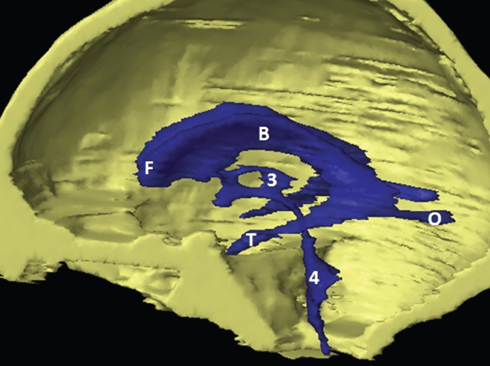
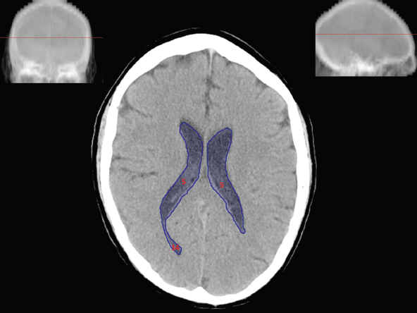
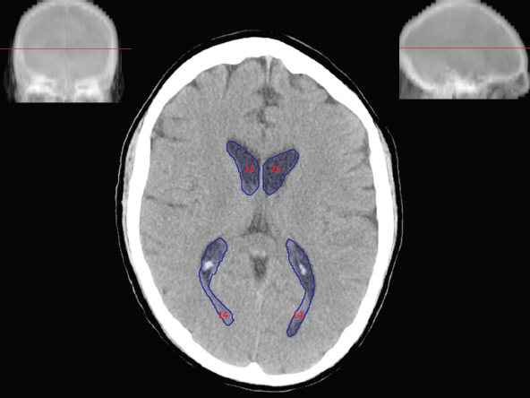
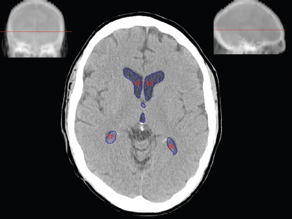
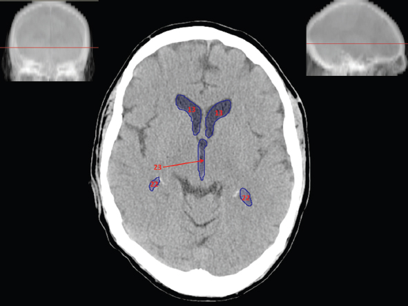
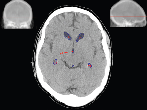
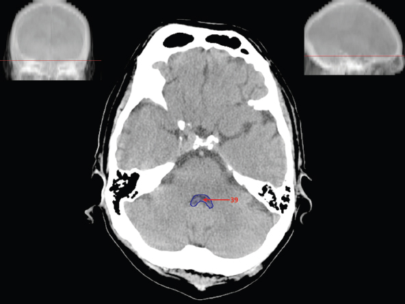
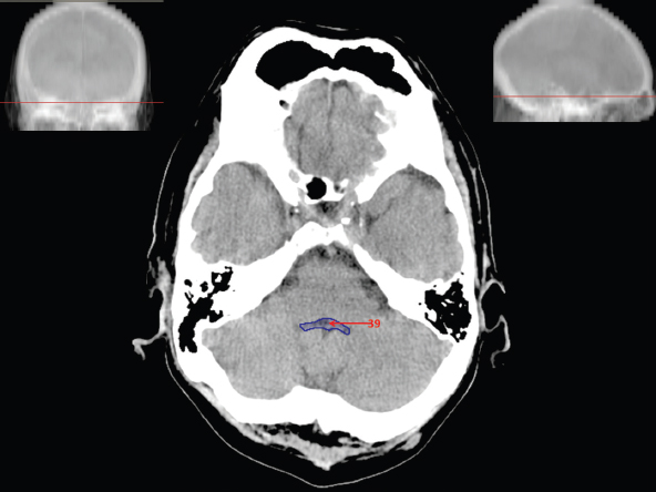
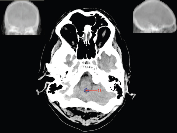
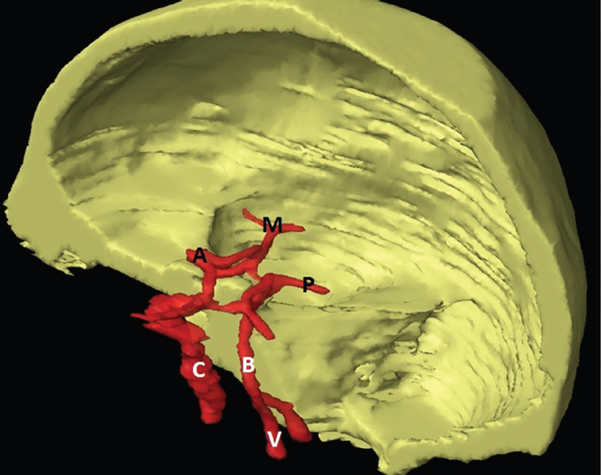
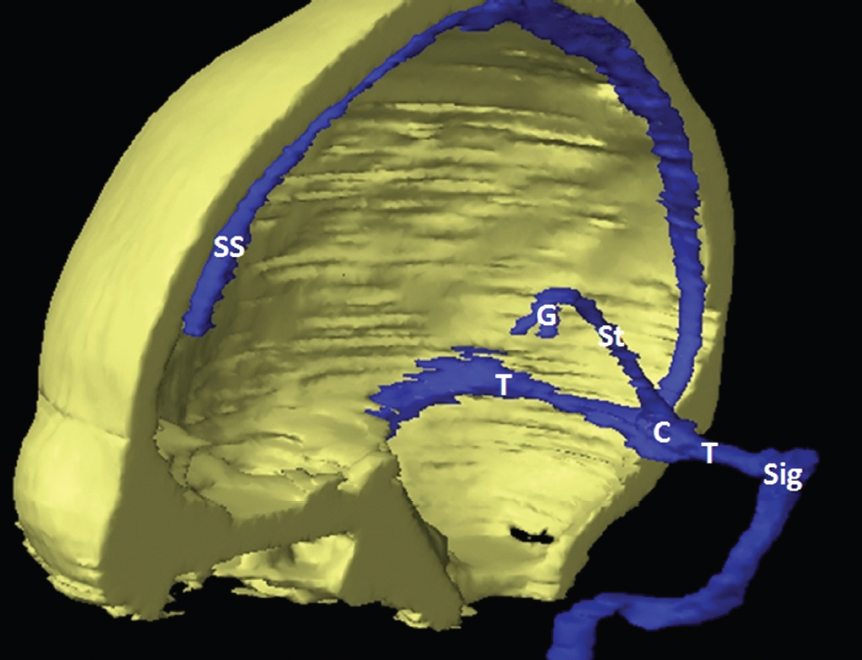
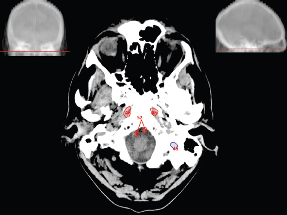
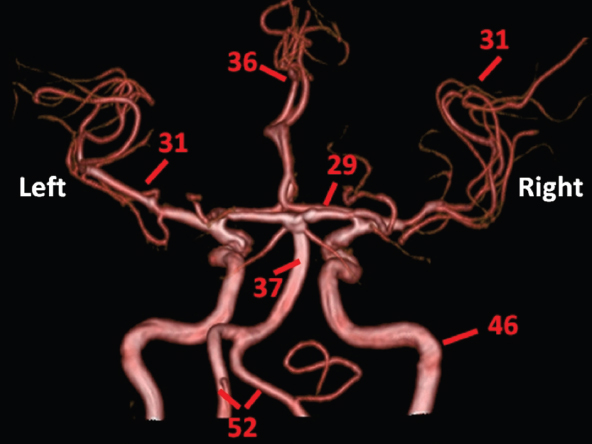
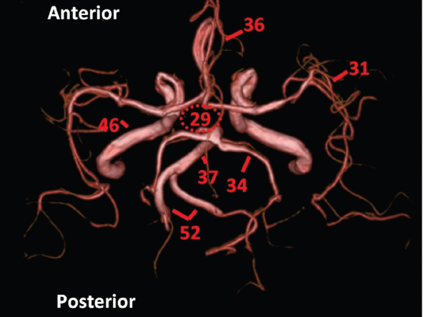
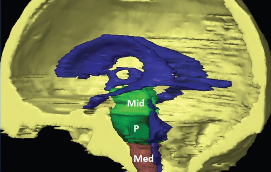
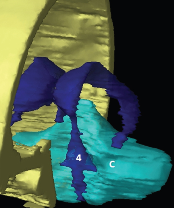
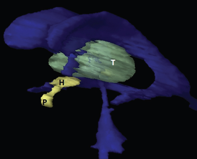
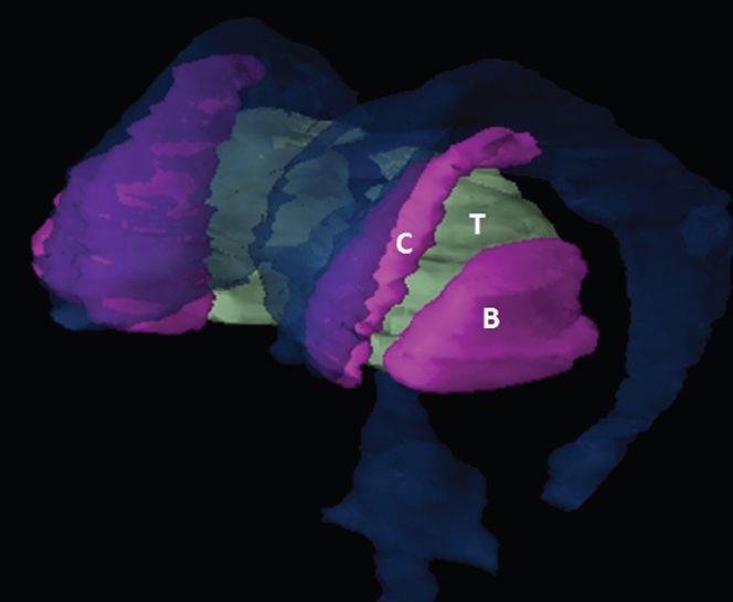
The size, shape and distribution of cerebrospinal fluid (CSF) spaces are important indicators of space-occupying mass lesions. The intracranial CSF spaces will show distortion, compression and possible midline shift, depending on the severity and location of the mass. For example, dilatation of the ventricular system caused by obstructive hydrocephalus will not only manifest itself with expanded ventricles, but will also cause effacement of other subarachnoid spaces around the brain, such as cisterns and sulcal grooves. An appreciation of the intracranial CSF spaces is vital since the presence of CSF is evident on most, if not all, CT and/or MRI sectional images throughout the cranium. CSF is predominantly produced via the choroid plexuses (chorion – Latin for delicate skin or outer layer, and plectere – Latin for plait or braid). CSF is essentially a watery, colourless fluid, of low density. When viewed on CT, it will have an appearance very similar to water, with approximately 0HU. This will give a natural inherent low density contrast when compared to adjacent brain tissue (about 36HU for grey matter, 28HU for white matter and over 200HU for the skull vault). As described earlier, it is vital to understand the location of the CSF, and there are two major CSF-containing compartments: the ventricles and cisterns. Figure 5.1.1 illustrates the ventricular system, as seen from the left side. Figure 5.1.1 The largest ventricles are the two laterals. They each have a body (B) with three protrusions comprising the frontal (F), occipital (O) and temporal (T) horns. These penetrate the frontal lobe, occipital lobe and t,emporal lobe respectively. The two lateral ventricles are separated by a thin wall known as the septum pellucidum. Holes in this wall allow CSF to pass through. The lateral ventricles lead into the third ventricle (3) via the interventricular foramina of Munro. The third ventricle is a midline structure sitting inferiorly and medially to the lateral ventricle bodies. The cerebral aqueduct exits from the infero-posterior aspect of the third ventricle and descends before expanding into the fourth ventricle (4). After the fourth ventricle, the CSF is conducted into the spinal column via the central canal. The cisterns are essentially openings in the subarachnoid space which are caused by separation of the arachnoid and dura mater, forming the pools or collections of CSF surrounding the brain. This also gives rise to CSF sulcal spaces, forming the readily recognisable patterns of cerebral and cerebellar sulcation between and surrounding the gyral convolutions on the external surface of the brain. The ventricular system and subarachnoid cistern spaces are fundamentally one space through which CSF circulates, and as such, the CT density appearances within each space should be the same. The choroid plexuses form infoldings of the walls of parts of the ventricles through choroidal fissures, on the floors of the bodies and horns of the lateral ventricles, and the roofs of the third and fourth ventricles. Pressure within the ventricular system and various cisterns around the brain is relatively low at lumbar puncture, so has minimal mass effect on surrounding brain tissue. Therefore it is important to realise that a solid lesion or regions of high pressure due to haemorrhage, for example, will have a mass effect on the lower pressure ventricular system, cisterns and sulcal spaces. This will cause deformation or compression of the CSF-filled spaces which will be apparent when comparing symmetry. As approximately 500ml of CSF is produced each day, any lesion that impedes CSF hydrodynamics will cause obstruction and subsequent dilatation of parts or all of the ventricular system, giving rise to hydrocephalus, which has recognisable traits in cross-sectional imaging. Figure 5.1.2 Figure 5.1.2 is the most superior of the images and shows the bodies of the lateral ventricles (5) either side of the falx cerebri. The left lateral ventricle displays minimal asymmetry when compared to the right; however this is within acceptable variances at this level. This could indicate slight discrepancies in positioning, but the rest of the anatomy is symmetrical, and this is more likely to represent mild normal ventricular asymmetry. The body of each ventricle displays a convexity away from midline with a curved appearance. The CSF spaces on the external surface of the brain can be seen between each gyral projection. These are termed sulcus singularly, and each sulcus is a gap or mildly tortuous elongated depression along the cortex of the surface of the brain that greatly increases the cortical surface area. Figure 5.1.3 Figure 5.1.3 depicts the lateral ventricle bodies forming the frontal and occipital horns. The right occipital horn (14) can be seen curving back into the occipital lobe, forming an ‘S’ shape. Within the central portions of the lateral ventricles (5) can be seen patchy feathered areas of slightly increased CT density. These are the choroid plexuses. The bodies of each lateral ventricle are separated in the midline by the septum pellucidum membranes. In 10% of the population, these two membranes are not fused, causing an elongated, CSF-filled projection between the lateral ventricles. This is the cavum septi pellucidi, and has in the past been referred to as the ‘fifth ventricle’. This term, however, is more widely used to describe a small CSF cavity within the conus medullaris at the tail end of the spinal cord which is present in a small percentage of the population. Figure 5.1.4 Figure 5.1.4 shows the frontal horns (13) of the lateral ventricles, separated in the midline by the anterior aspect of the septum pellucidum. The frontal horns are triangular in shape in cross-section, and are indented laterally. Figure 5.1.4 also demonstrates areas of increased CT density within each body of the lateral ventricle. These are calcifications within the choroid plexuses, and are an expected finding. Extending from the posterior aspect of the body of each lateral ventricle, the narrower occipital horns (14) are tracking posteriorly deep into each occipital lobe curving around the corpus callosum medially towards the midline. Although relatively symmetrical in this example, it is not uncommon to show minor asymmetrical discrepancies in the size and shape of both the frontal and occipital horns. This should not be confused with disease. Figure 5.1.5 Figure 5.1.6 Figure 5.1.7 Figures 5.1.5 to 5.1.7 show the temporal horns (22) of the lateral ventricles in short axis. They are quite small in cross-section. The temporal horns are narrow, ventricular projections curving laterally initially and then anteromedially deep into each temporal lobe. It is not unusual to lose sight of the temporal horns. They are sensitive to changes in intraventricular pressure and tend to display disproportionate levels of dilation compared to the rest of the ventricular system. This imaging sign is often used as an early prognostic indicator for obstructive hydrocephalus. The third ventricle (23) is well demonstrated in Figure 5.1.6 as a centrally located CSF-filled narrow structure. The third ventricle has several indentations or recesses caused by adjacent anatomy: optic and pituitary infundibular recess anteriorly and suprapineal and pineal recesses posteriorly. Figure 5.1.8 Figure 5.1.8 shows the fourth ventricle (39). In three dimensions, this is quite a complex diamond shape with numerous indentations or recesses caused by adjacent neuroanatomy, similar to the third ventricle. In axial section, it displays a curved ‘bean’ shape, with a posterior concavity caused by the cerebellar vermis. Figure 5.1.9 Slightly inferiorly, as demonstrated in Figure 5.1.9, the posterior wall of the fourth ventricle has a blind ended pointed outpouching called the fastigium. Just inferior to this, visible in Figure 5.1.10, the three apertures or foraminae communicating with the subarachnoid spaces can be seen. The lateral foraminae (foraminae of Luschka) are seen laterally and the centrally located foramen of Magendie can be seen posteriorly from the fourth ventricle. Figure 5.1.10 Figure 5.1.10 shows the CSF within the fourth ventricle communicating with the central canal (51) via the obex of the cord. From the three foraminae, the CSF circulates through the subarachnoid spaces and pools in various cisterns around the brain. The first cistern that CSF drains into is the cerebellopontine cistern, anterior and lateral to the cerebellum and pons as its name suggests. The pontine cistern is seen in Figure 5.1.10 surrounding the basilar artery. Another well recognised and described cistern is the quadrigeminal cistern, seen in Figure 5.1.7 as a midline curved CSF space situated between the temporal horns. Separating the temporal and frontal lobes, the lateral sulcus or ‘insular cistern’ can be seen in Figures 5.1.6 and 5.1.7. This cistern is more frequently known as the Sylvian fissure. An easy feature to recognise when assessing CSF spaces for evidence of compression is a ‘smily face’, where on a midsection scan, the ‘eyes’ are formed by the frontal horns of the lateral ventricles, the ‘nose’ is formed by the third ventricle and the ‘smiling mouth’ by the curved quadrigeminal cistern. Intracranial structures are supplied with blood by the internal carotid and vertebral arteries. The internal carotid arteries penetrate the skull through the carotid canals and then curve their way up along the lateral border of the clivus of the sphenoid bone before joining the Circle of Willis. The vertebral arteries curve over the first cervical vertebra and join in the midline to form the basilar artery. This then passes superiorly and anteriorly until it meets the Circle of Willis. The Circle of Willis is a ring-shaped anastomosis that connects these major arteries and thus ensures a constant supply of blood to the brain in the event of occlusion of one of these vessels. Figure 5.2.1 illustrates how the Circle is supplied by the internal carotid arteries (C) anteriorly and basilar artery (B) posteriorly. Note the formation of the basilar artery by the joining of the vertebral arteries (V). The right internal carotid is hidden by the skull in this diagram. Blood exits the Circle via the anterior (A), middle (M) and posterior (P) cerebral arteries. These in turn rapidly divide to supply the anterior, central and posterior parts of the brain respectively. Figure 5.2.1 Venous drainage in the brain is accomplished via interconnected veins that drain into large sinuses as illustrated in Figure 5.2.2. Blood from the peripheral superior region is drained into the superior sagittal sinus (SS). This runs along midline from the anterior of the skull over the superior aspect and down the occipital bone. More internal regions drain blood into the inferior sagittal sinus, while the centre of the brain drains via the great cerebral veins of Galen (G). The inferior sagittal sinus and veins of Galen meet to form the straight sinus (St). This runs posteriorly and inferiorly to join with the superior sagittal sinus at a widened region known as the confluence of sinuses (C). This is situated just beneath the occipital bone at the internal occipital protuberance. From the confluence of sinuses, blood runs laterally and anteriorly through the transverse sinuses (T) along the internal surface of the occipital bone. Once they reach the petrous ridge of the temporal bone, the transverse sinuses form the sigmoid sinuses (Sig) and snake down to exit the brain via the jugular foramen to form the internal jugular veins. Figure 5.2.2 CT imaging the whole intracranial circulation on one series of images and subsequent reformatting is complex. This is usually achieved by a multiphased contrast-enhanced volume CT acquisition, resulting in two imaging runs; an early arterial phase, followed by a second venous phase or combined with the use of perfusion imaging. Current practices used for radiotherapy planning do not conventionally utilise these techniques. Other imaging modalities also tend to be used alongside or instead of CT, such as conventional angiography and MRI angiography (MRA). Therefore it is quite difficult to fully demonstrate intracranial circulation, both arterial supply and venous drainage, without utilising several imaging techniques. The following images demonstrate major intracranial cross-sectional morphology, ensuring standardisation of descriptive text and imaging. Creating a 3-dimensional model of the entire arterial circulation is challenging, as current outlining software struggles to demonstrate the tortuosity of more peripheral intracranial arteries. To accompany Figure 5.2.1, the reader should also use Figure 5.2.13 to assist understanding of the whole arterial supply. This is a 3-dimensional CT volume rendered image acquired on a diagnostic platform, specifically designed for the detection of small vessel anomalies so the depicted arterial vascularity is highly detailed and complex. The accompanying text also describes firstly the intracranial venous drainage (as this is most evident from the vertex inferiorly from Figure 5.2.3 and inferior to this level) and then the intracranial arterial supply, rather than mixing the two in the same body of text. Describing and understanding one vascular system at a time is less complex than learning both simultaneously. Figure 5.2.3 When assessing intracranial venous drainage, there are essentially two main systems. The superior group comprises the sagittal (superior (3) and inferior sagittal sinus where visualised), transverse (24) and straight (12) dural sinuses (Figure 5.2.5). The basal group includes the cavernous and superior and inferior petrosal sinuses. Therefore, with a few exceptions, the vast majority of intracranial venous drainage ultimately flows into the internal jugular veins via the dural venous sinuses. Figure 5.2.4 The superior venous sinuses are channels formed between layers of dura and internal periostial lining of the internal skull periosteum. CSF drains into the venous blood and back into the normal circulation. Unlike other venous channels within the body, these sinuses are just channels or cavities through which the blood flows. There are no valves or muscular walls present. This gives the sinuses their characteristic triangular shape in cross-section, as seen in Figure 5.2.4 in both anterior and posterior aspects of the superior sagittal sinus (3). Figure 5.2.3 shows the superior sagittal sinus (3), formed by the two layers of falx cerebri folding inwards between the two cerebral hemispheres. The superior sagittal sinus (3) originates just distal to the crista galli on the cribriform plate and extends along the midline, enlarging in diameter as it tracks posteriorly. It may not be visible until level with the coronal suture. The superior sagittal sinus is normally a singular midline structure; however it may be slightly off centre and may even also bifurcate before its termination. Figure 5.2.5 As the superior sagittal sinus (3) flows more posteriorly it descends towards the occipital bone where it joins the confluence of sinuses (26) seen in Figure 5.2.6, just superior to and anterior to the internal occipital protuberance. The straight sinus (12) is more central than the superior sagittal sinus and, rather than running along the inner calvarial vault, it is formed at the junction of the falx cerebri and the tentorium cerebelli (a sheet separating the cerebrum from the cerebellum). Thus it is normally a midline structure, although it can be offset towards the left, where it drains into the left transverse sinus (24), seen in Figure 5.2.7. The smaller inferior sagittal sinus and internal cerebral veins also drain into the straight sinus along its course. As the straight sinus (12) descends inferiorly from the anterior edge of the tentorium cerebelli, it follows a relatively steep descent and therefore is not normally seen in longitudinal cross-section. As demonstrated in Figure 5.2.5, it is frequently seen in a short axis cross-section. Figure 5.2.6 Figure 5.2.7 At the confluence of sinuses (26) the sinuses split and drain laterally along the transverse sinuses (24). These are usually asymmetric and demonstrate a dominant side. As the transverse sinuses are relatively straight, instead of curvilinear, it is likely that a greater length will be visualised on axial slices such as Figures 5.2.6 and 5.2.7. Figure 5.2.8 Figure 5.2.9 Figure 5.2.10 The transverse sinuses (24) change path at the base of the petrous temporal bone, and descend in a sigma shape as the sigmoid sinuses (45), as seen in Figures 5.2.7 to 5.2.10. Figure 5.2.11 Figure 5.2.12 In Figures 5.2.11 and 5.2.12, the sigmoid sinuses can be seen draining into a dilated section called the jugular bulb, clearly seen in Figure 5.2.11 on the right, but not as clear on the left. From here, the sinuses drain into each internal jugular vein and exit the skull via the jugular foraminae. Throughout many other parts of the body, both venous and arterial systems mirror each other so an artery will usually have a matching vein flowing in the opposite direction adjacent to it. The intracranial arterial supply is very different from its venous drainage, as seen in Figures 5.2.1 and 5.2.2. Figure 5.2.13 Figure 5.2.14 Figures 5.2.13 and 5.2.14 are more detailed 3-dimensional images of the intracranial arterial supply and the tortuosity of the vessels can be appreciated. Figure 5.2.13 shows the intracranial circulation from the posterior aspect and clearly demonstrates the various branches. Figure 5.2.14 demonstrates the same anatomy from the superior aspect, and the Circle of Willis can be seen central to the image, formed by anastomotic communicating vessels joining the six main cerebral vessels. These are the right and left anterior, middle and posterior cerebral arteries. The anterior aspect of the Circle of Willis is supplied by both internal carotid arteries. One interesting point of note is the path of the internal carotid arteries. The internal carotid vessels undergo a seemingly unnecessarily tortuous path before supplying the anterior circulation of the Circle of Willis. The complex path of both internal carotid vessels (46) can be seen in Figures 5.2.13 and 5.2.14. Following their entry into the skull base via the carotid canal, they curve anteriorly and lie within the foramen lacerum either side of the sella turcica within the ‘cavernous sinus’. From here, the cavernous segments then bend sharply back on themselves in a U shape, known as the carotid siphon. They exit the cavernous sinus and the ophthalmic segments then project posteriorly before bending superiorly to join the Circle of Willis. This extremely tortuous path can be seen in axial section in Figures 5.2.9 to 5.2.12. The vessels are seen immediately lateral to the sella turcica in Figures 5.2.9 and 5.2.10. Various smaller vessels branch off the internal carotid artery before it joins the circle of Willis (29); however these are not usually seen on normal resolution CT scanning. The posterior circulation is formed by the vertebrobasilar system. The two vertebral arteries (52) are well demonstrated in Figures 5.2.13 and 5.2.14 in three dimensions. Figure 5.2.12 demonstrates this in axial section, and the two vertebral vessels (52) are seen just anterior to the superior aspect of the spinal cord and immediately posterior to the anterior aspect of the foramen magnum. Slightly superiorly, Figure 5.2.11 shows the presence of just one vessel, the basilar artery (37) following the fusion of the two vertebral vessels. From here the basilar artery ascends ventral to the pons in the midline, seen in Figures 5.2.8 to 5.2.10. The basilar artery can be relatively eccentric and its path can extend off centre with varying configurations of smaller branches. The smaller branches are not well visualised on low resolution CT sections; however branches of the superior cerebellar and posterior inferior cerebellar arteries may be seen if contrast enhancement is sufficient. Immediately superior to the superior cerebellar arteries, the basilar bifurcates into the right and left posterior cerebral arteries (34). The vessel curves posteriorly around the pons and travels through the ambient and quadrigeminal cisterns, as seen in Figure 5.2.8. Here the left posterior cerebral artery can be discerned in Figure 5.2.14. From here the vessels further subdivide and supply parts of the occipital and temporal cerebral lobes. Figure 5.3.1 Although fabulously complex and intricate on a microscopic level, the macroscopic central nervous system (as seen on CT) is relatively straightforward. As the spinal cord penetrates the skull via the foramen magnum, it bulges to form the medulla oblongata (Med), which is the most inferior part of the brainstem. Above the medulla lies the pons (P) with its characteristic double swellings on the anterior surface. Above the pons is the midbrain (Mid), which allows the brainstem to communicate with the rest of the brain. Figure 5.3.1 illustrates the relationship between these three components of the brainstem. The ventricular system is also illustrated, demonstrating the close relationship between the brainstem and fourth ventricle. The pons forms the connection between the cerebellum and the brainstem. The cerebellum lies posterior to the brainstem and comprises two hemispheres with a small central vermis. The pons and cerebellum enclose the fourth ventricle (4) with the cerebellum (C) forming the posterior wall, as seen in Figure 5.3.2. Figure 5.3.2 Figure 5.3.3 Superior to the midbrain can be found the paired lobes of the thalamus. The thalamus encloses the third ventricle, as seen in Figure 5.3.3. The thalamus (T) maintains several connections (anterior, middle and posterior fornix) that cross the ventricle and allow communication between the lobes. Although of limited interest to radiotherapy, the small midline pineal gland can usually be seen on CT due to its tendency to calcify. It is located posteriorly to the thalamus and is a useful and reliable landmark as well as an indicator of asymmetry and midline shift. Anteriorly and inferiorly to the thalamus lies the hypothalamus (H) region. This is a collection of small grey matter ‘nuclei’. Extending inferiorly from the hypothalamus is the pituitary gland (P), connected by a thin stalk known as the infundibulum. The pituitary can be seen protruding from the hypothalamus in Figure 5.3.3. The pituitary sits in a depressed region of the sphenoid bone called the sella turcica (or Turkish Saddle). Due to its small size, it can sometimes be hard to visualise unless narrow slices are used. Figure 5.3.4 There are other grey matter nuclei dotted around the brain and many of these are grouped together to form the basal ganglia. CT usually lacks the resolution to allow clear differentiation between the different nuclei and this book combines structures such as the putamen, globus pallidus and substantia nigra into the overarching term basal ganglia. Most of the basal ganglia nuclei are located laterally to the lateral ventricles. The caudate nucleus is perhaps the most easily visualised of the nuclei since it forms the inferior boundary of the frontal horn of the lateral ventricles. Each caudate nucleus curves over a thalamus lobe in a C-shape. The anterior section is enlarged and is known as the head. Figure 5.3.4 shows the caudate nucleus (C) curving along the lateral inferior surface of the lateral ventricle frontal horns. The rest of the basal ganglia (B) can be seen laterally to the thalamus (T). Figure 5.3.5
5.1Cerebrospinal Fluid Spaces

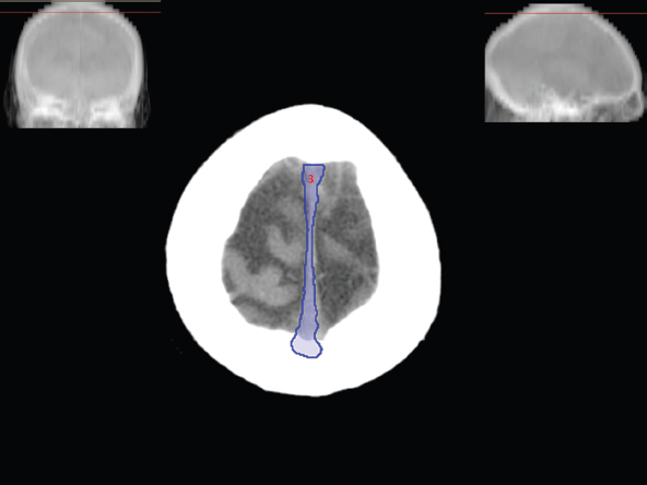
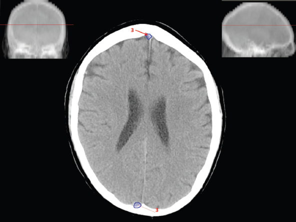
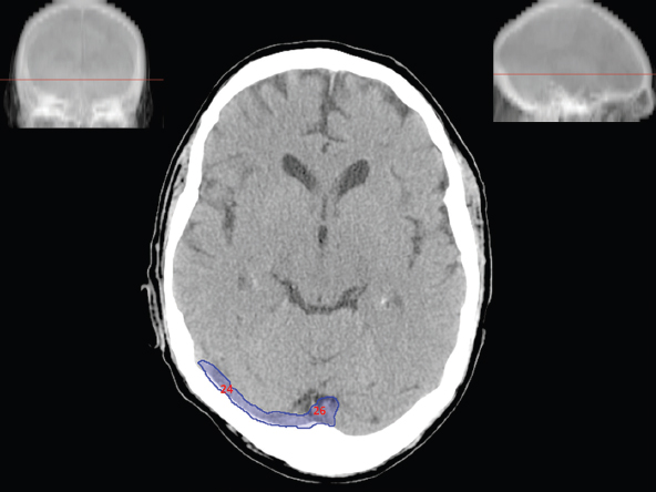
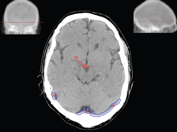
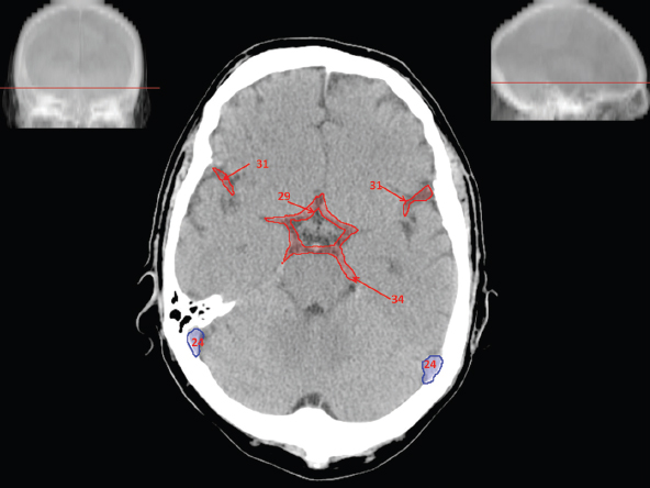
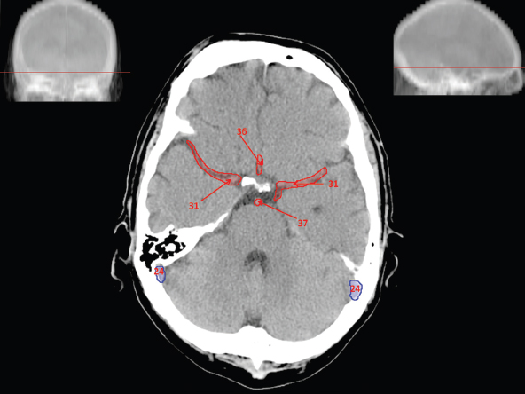
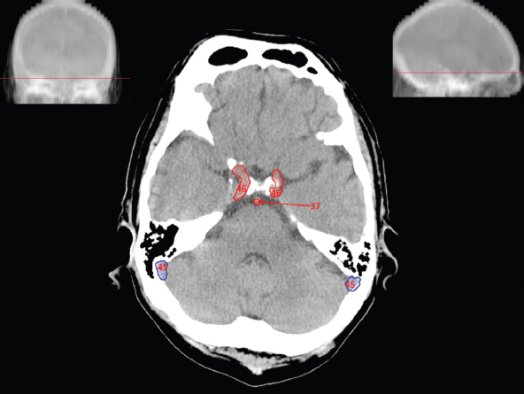
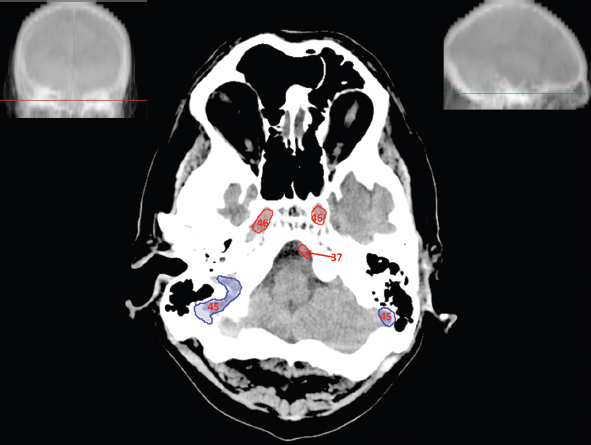
5.2Circulatory System

5.3Central Nervous System

Related posts:
Stay updated, free articles. Join our Telegram channel

Full access? Get Clinical Tree


