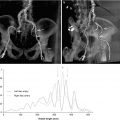
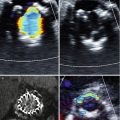
Fig. 33.1
CoreValve (left, courtesy of Medtronic). SAPIEN 9000 TFX (bottom right) and SAPIEN XT 9300 TFX (top right) valves (Adapted with permission from Jayasuriya et al. [27])
The PARTNER trial, published in 2010, compared TAVR with medical therapy among patients with severe AS considered unsuitable surgical candidates for AVR. The all-cause death rate at 1 year with TAVR was 30.7 % compared to 50.7 % with standard medical therapy. Patients undergoing TAVR experienced improved quality of life as well, with the rate of heart failure symptoms (NYHA Class III or IV) 25.2 % in the TAVR group compared to 58 % in the standard therapy group. However, incidence of early strokes or vascular complications within 30 days of procedural intervention was higher in the TAVR group, although only vascular complications manifested statistically significant differences [3]. Two-year follow-up data from the original PARTNER trial demonstrates the persistence in life-years gained, with mortality in the TAVR group 43.3 % versus 68 % in the standard therapy group. Similarly, rates of rehospitalization for the TAVR patients over a 2-year period were also significantly less than those in the standard therapy group (35 % versus 72.5 %). The rate of strokes over the 2-year follow-up period was 13.8 % for TAVR, and 5.5 % for the standard therapy group, with most of the early TAVR strokes being ischemic and late TAVR strokes being hemorrhagic [22].
Intraprocedural Imaging of the Aortic Valve
Two-dimensional transthoracic echocardiography is used to assess aortic stenosis severity in order to qualify for TAVR placement. Multiple modalities are used in evaluating the severity of AS, including noninvasive and invasive hemodynamic measurements in the echocardiography and catheterization laboratory. Real-time fluoroscopic and transesophageal echocardiographic (TEE) guidance are used to evaluate cardiac function, locate the position of the native valve, and deploy the bioprosthetic valve. But as can be seen in Fig. 33.2, fluoroscopy provides limited information about the severity of aortic stenosis, correct sizing of the aortic annulus, or assessing for cardiac function.
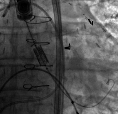

Fig. 33.2
Fluoroscopic view of the Edwards Sapien Valve across the aortic valve pre-deployment. The ability to visualize the aortic valve annulus using fluoroscopy without contrast is limited unless the aortic valve is significantly calcified. In this example, there is limited aortic valve calcification. Transesophageal echo provides valuable supplemental information to guide the operator and possibly limit contrast injections
Both 2D TTE (preprocedurally) and 2D TEE (intraprocedurally) have been used to address these limitations of fluoroscopy, but the appreciation of spatial relationships with 2D echocardiography is limited. Consequently, operators have now started to utilize 3D echocardiography before, during and after the deployment of the bioprosthetic aortic valve to better assess the aortic valve diameter and catheter orientation. The majority of applications for 3D echocardiography have been with TEE given that 3D TTE has very poor resolution, making it of little practical use for pre- or intraprocedural TAVR. 3D TEE imaging offers precise multiplanar dimensional measurements as well as superior anatomic detail of the stenotic valve, aortic root, and subvalvular anatomy, the relationship of the aortic valve and the anterior mitral leaflet (Fig. 33.3a–d), and can identify the distance of the coronary ostia to the aortic annulus. Furthermore, post-deployment, 3D TEE can demonstrate the exact location and severity of a paravalvular or transvalvular leak.
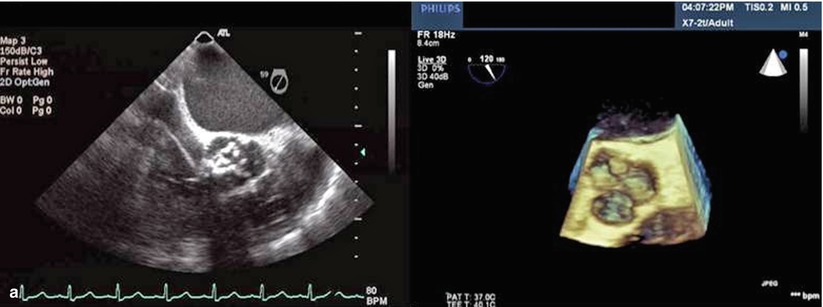
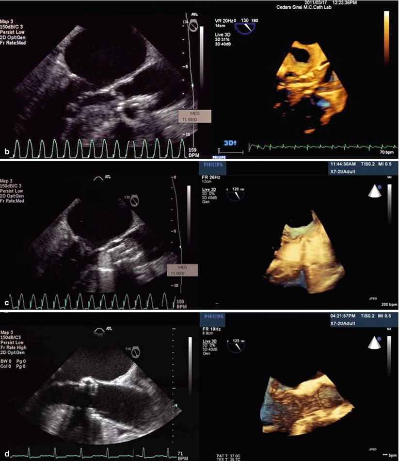


Fig. 33.3
(a) Comparison of 2D and 3D TEE short-axis view across the aortic valve. Note how one can better appreciate the anatomic relationship between the calcified aortic cusps and the aortic annulus in the 3D TEE relative to 2D TEE. (b) The relationship between the beginning and end of the crimped Sapien valve relative to the native aortic valve is more easily seen in the 3D TEE versus 2D TEE. (c) Deployment of the Sapien valve. (d) The precise location of the Sapien valve relative to the aortic annulus, left ventricular outflow tract, and the anterior mitral leaflet is more easily seen with the 3D TEE
During deployment of the bioprosthetic aortic valve, 2D and 3D TEE along with fluoroscopy are used to verify bioprosthesis positioning in the aortic annulus. Altiok et al., in addition to demonstrating the advantages of 3D imaging in procedural guidance, showed a high degree of correlation between the coronal and sagittal 3D TEE versus multidetector computed tomography (MDCT) aortic annulus diameters (23.6 ± 1.89 mm vs. 23.46 ± 2.07 mm and 22.19 ± 1.96 vs. 22.27 ± 2.01 mm, respectively). Data suggest that 3D cross-sectional measurements using MDCT can be used to accurately assess the annular size of the aortic valve and possibly help reduce the risk of moderate or severe paravalvular aortic regurgitation [19, 20]. Jilaihawi et al. published a single-center retrospective study showing that 3D MDCT was superior to 2D echocardiography for correctly sizing the aortic valve annulus for TAVR. They showed a significant decrease in post-TAVR paravalvular aortic regurgitation (PAR) by using multi-slice CT rather than 2D echocardiography to measure the aortic valve annulus [21]. Although these data underscore the superiority of 3D versus 2D imaging modalities, there are still no multicenter randomized studies that compare the clinical outcomes of patients who have their aortic annulus measured with 3D MDCT or 3D TEE versus 2D TEE. These types of studies are necessary because due to a concern that increased prosthesis size generally dictated by cross-sectional imaging may theoretically lead to increased rates of catastrophic aortic annulus rupture or dissection (Table 33.1).
Table 33.1
Relative usefulness of TEE versus CT
2D TEE | 3D TEE | MDCT | |
|---|---|---|---|
AS severity | ++ | + | +/− |
Aortic valve morphology | ++ | ++ | +a |
Calcium distribution | + | + | ++ |
Aortic root orientation | −− | −− | ++ |
Aortic annulus diameter | ++ | ++ | ++ |
Aortic root morphology | ++ | ++ | ++ |
Coronary ostia to aortic annulus distance | +/− | + | ++ |
TAVR Pre-deployment
Once a patient has met criteria for TAVR, precise measurements of the aortic annulus are needed in order to correctly size the bioprosthetic valve. As can be appreciated in Fig. 33.4, the aortic valve annulus is usually wider in the coronal cross-section than the sagittal – producing an oval aortic valve annulus. This observation that the aortic valve annulus is oval has been observed in several other studies and has been found to have important clinical outcome implications [23].
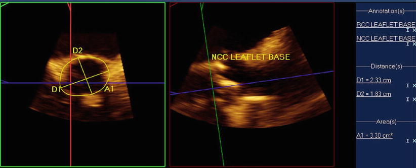

Fig. 33.4
Multiplanar assessment of aortic annulus using 3D TEE: Left panel demonstrates short-axis view of the aortic valve. Note the difference in the sagittal and coronal measurements, indicating that the aortic valve annulus is oval. Right panel shows an orthogonal measurement of the aortic annulus
Although there remains controversy surrounding the optimal methodology for measuring the aortic valve annulus, there are several techniques that are currently being used to measure it as there is no gold standard. One of the most common techniques is using 3D TEE multiplane assessment of the aortic annulus, where simultaneous orthogonal views can be obtained in the sagittal and coronal plane during systole (Fig. 33.4). A similar approach is used with 2D TEE, where the sagittal diameter of the aortic valve is measured between the base of the right and noncoronary cusps from a mid-esophageal long-axis view of 110–140 ° during systole. A mid-esophageal short-axis view of 30–60° or an X-plane from the long-axis view is used at obtain the coronal diameter. Once the aortic annulus dimensions are noted, the sinus of Valsalva, the sinotubular junction, and the ascending aorta are also measured.
It is important to correctly measure the sagittal and coronal dimensions of the aortic valve annulus because undersizing of the bioprosthetic valve can lead to significant paravalvular leak, which if greater than mild, is an independent predictor of a twofold increase in late mortality [16, 24]. Furthermore, undersizing of the aortic valve can lead to dislodgement and embolization of the valve, while oversizing can cause aortic annular rupture, quickly evolving to cardiac tamponade and death. Given the higher anatomic spatial relationship of 3D TEE, it is hypothesized that it can better assess the true dimensions of the aortic valve annulus. But the lack of a gold standard for measuring the aortic valve annulus makes it difficult to study in clinical trials.
The long-axis view is typically the preferred view for imaging during valve implantation. As can be appreciated in Fig. 33.5, a major advantage of 3D TEE is that it can be used to image the aortic valve from the aorta or left ventricular outflow tract, aiding in the assessment of septal hypertrophy as well as evaluating the spatial relationship of the aortic annulus to the anterior mitral leaflet and the interventricular septum.
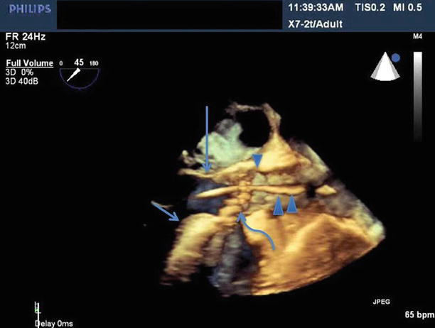

Fig. 33.5
Benefit of 3D TEE long-axis view showing the LVOT, anterior mitral leaflet (long arrow), interventricular septum (short arrow), aortic valve (curved arrow), the TAVR guide catheter (double arrowhead), sinotubular junction (single arrowhead)
Most patients with severe aortic stenosis have undergone cardiac remodeling, altering the anatomic relationship of normal cardiac structures. Annular remodeling in aortic stenosis can lead to a decrease in the expected distance from the aortic valve annulus to the coronary ostia. Furthermore, patients with AS often develop left ventricular hypertrophy as a result of chronically elevated left ventricular systolic pressures, resulting in symmetric and asymmetric septal hypertrophy. 3D TEE allows for precise assessment of the spatial relationship between the bioprosthetic valve, the interventricular septum, the coronary ostia, and the anterior mitral leaflet.
A bioprosthetic valve that is deployed too far into the left ventricular outflow tract (LVOT) can embolize into the left ventricle, often requiring open heart surgery to remove it. If the bioprosthetic valve is placed too far into the LVOT, but remains anchored in the annulus, there is the risk that its lateral struts can interfere with proper movement of the anterior mitral leaflet and result in mitral regurgitation. Patients with asymmetric septal hypertrophy may need to have the valve deployed higher in order to avoid the development of aortic subvalvular gradients and under-expansion of the bioprosthetic valve. But deploying a valve too high poses another problem since it can lead to obstruction of the coronary ostia. The distance from the ostium of the left coronary artery to the coronary cusp is of importance because calcium on the coronary cusp adjacent to the coronary ostium can be dislodged into the coronary artery during valve deployment.
Stay updated, free articles. Join our Telegram channel

Full access? Get Clinical Tree


