Intravascular Brachytherapy
24.1. Introduction
Coronary artery disease is most commonly treated using bypass surgery or percutaneous transluminal coronary angioplasty (PTCA). A major problem with PTCA, however, is the high incidence of restenosis and recurrence of artery blockage at the site of treatment. Restenosis is usually arbitrarily defined as a narrowing of the lumen by 50% or greater in diameter compared to the adjacent normal-appearing segments. Although the occurrence of restenosis is significantly reduced by the implantation of coronary stents, the restenosis rate following balloon angioplasty in randomized trials is 30% to 40% (1).
Most restenosis after angioplasty or stenting is caused by thrombosis or blood clotting at the PTCA site, which can be prevented partially by using anticlotting drugs. However, another process, which begins within days after angioplasty, is the neointimal growth of tissues prompted by the wound-healing process following tissue injury by angioplasty. This component of restenosis cannot be prevented by anticoagulants or stents.
Intraluminal irradiation of coronary and peripheral arteries together with balloon angioplasty and/or stent implantation significantly lowers the rate of neointimal formation, thereby reducing the rate of restenosis to well below 10% (2). Radiation kills cells and inhibits the growth of neointimal tissues in a manner similar to its effect on benign diseases such as keloids and heterotopic bone formation. Basic radiation biology and vascular pathology are discussed by several authors (3,4,5).
24.2. Treatment Volume
A. Arterial Anatomy
The arteries carry blood from the heart to various parts of the body. The main artery, the aorta, is the largest blood vessel (2–3 cm in diameter) and carries blood from the left ventricle of the heart to the branching arteries and capillaries in all the body organs and tissues, including the heart muscle. The coronary arteries are blood vessels lying on the outer surface of the heart and the peripheral arteries supply blood to other organs and tissues. The luminal diameter of arteries ranges from 3 to 5 mm initially and tapers slowly through their path length. Within this range, the peripheral arteries tend to be of larger diameter than the coronary arteries. The minimum normal artery diameter required for angioplasty and stenting is approximately 3 mm.
The inside of the arteries is lined with a layer of cells called endothelium. Next to the endothelium is the connective tissue layer, the intima, followed by layers of elastic membrane, smooth muscle cells, and elastic tissues. The outermost layer of the arteries is called adventitia, made up chiefly of collagenous fiber.
B. Angioplasty and Restenosis
The arteries can be partially blocked due to atherosclerosis or plaque formation. Reduction of their lumen diameter compromises the flow of blood and the delivery of oxygen to the body tissues. As an alternative to a major surgical procedure such as bypass surgery, balloon angioplasty is used to dilate the lumen diameter. This stretching action often ruptures the internal elastic lamina of the wall and causes fissures in the medial layers. The acute risk of the angioplasty procedure is thrombosis that can be controlled by drugs, as mentioned previously. The more protracted risk, however, is that of restenosis by neointimal hyperplasia. This process involves growth of new tissues in the
cracks and crevices of the arterial wall caused by angioplastic injury. Although implantation of stent angioplasty reduces the overall rate of restenosis by approximately 50%, it does not prevent neointimal growth and may, in fact, stimulate the process.
cracks and crevices of the arterial wall caused by angioplastic injury. Although implantation of stent angioplasty reduces the overall rate of restenosis by approximately 50%, it does not prevent neointimal growth and may, in fact, stimulate the process.
C. Target Volume
Target volume for intravascular brachytherapy (IVBT) is confined to the region of angioplasty. Typically, it is 2 to 5 cm in length of artery and 0.5 to 2 mm in thickness of arterial wall. Occasionally, these dimensions may be exceeded depending on the location and extent of the disease. With 3 to 5 mm of luminal diameter, the radial range of treatment may extend as far as to about 5 mm from the center of the artery.
Because of the severity of inverse square falloff of radiation at short distances, transluminal irradiation with intravascular brachytherapy produces highly conformal dose distribution, delivering a high dose to the arterial wall while sparing surrounding normal vessels or myocardium. Again, because of the predominance of the inverse square law effect, penetrating power of radiation, depending on energy and modality, is not critically important, except with regard to dose rate or duration of implant and radiation protection of personnel involved with the procedure. β-Particle sources, in general, give higher dose rates and provide greater radiation protection compared to the γ-ray sources.
The depth of dose prescription for intracoronary irradiation is recommended by the American Association of Physicists in Medicine (AAPM) (6) to be 2 mm from the center of the source and for the peripheral arteries 2 mm beyond the average lumen radius. For each case, dose distribution in at least three planes perpendicular to the catheter and along its length should be determined. In addition, average, maximum, and minimum doses within the target volume should be reported (6).
24.3. Irradiation Techniques
Intravascular brachytherapy techniques may be classified into two categories: temporary implants (sealed sources or liquid-filled balloons) and permanent implants (radioactive stents). Each method has its advantages and limitations, but the catheter-based sealed source is the most commonly used method of treatment. It is the preferred method because of its better control of dose delivery. A variety of β- and γ-ray sources have been used for endovascular therapy, although the choice of one modality over the other is yet not clearly established. The pros and cons of a few sources and devices are discussed below.
A. Radiation Sources
Typical dosimetric requirements of a temporary intravascular implant are (a) to deliver a target dose of 15 to 20 Gy to a 2- to 3-cm length of the arterial wall involved at a radial distance of about 2 mm from the source center, (b) to minimize the dose to tissues outside the region of angioplasty, and (c) to take as little time as possible for completion of the procedure, that is, provide target dose rates on the order of 5 Gy/min or greater. These requirements suggest the suitability of high-energy β sources such as strontium-90, yttrium-90, and phosphorus-32 or high-activity γ sources such as iridium-192. The latter could be a high-dose-rate (HDR) afterloading unit with the source dimensions small enough to allow intravascular brachytherapy.
The β sources have several advantages over γ sources: higher specific activity, higher dose rate, longer half-life, and greater radiation safety for the patient as well as personnel. The major disadvantage of β sources, however, is the extremely rapid radial dose falloff within the target region; γ sources such as 192Ir provide relatively more uniform target dose, governed primarily by the inverse square law falloff with distance, but require high activity to yield a reasonably high dose rate (≥5 Gy/min). Consequently, radiation protection problems with such sources become more significant. Although the HDR afterloaders using γ sources could provide sufficiently high dose rate, they would require expensive shielding of the catheterization laboratories.
Table 24.1 contains a list of possible isotopes that have been or could be used for intravascular brachytherapy. The last column shows the activities required to obtain a dose rate of 5 Gy/min to a 2-cm length of a vessel at a radial distance of 2 mm from the source center. It is seen that the γ sources, because of lower specific activity, require much higher activities than the β sources for a catheter-based intravascular procedure. On the other hand, a permanent radioactive stent using 48V requires only 1 μCi to produce the same dose rate.
Although dose rate per unit-activity favors β emitters, radial dose distribution is better for the γ sources, if it is assumed that the dose uniformity across the target volume is radiobiologically beneficial. This assumption has not been clinically validated but it seems logical, based on experience in
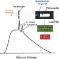
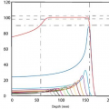
conventional radiation therapy. Figure 24.1 compares radial dose distribution as a function of radial distance for some of the sources listed in Table 24.1. Nath and Liu (7) have studied radial dose function (g) for point sources of photons and electrons using Monte Carlo simulation. Their data show that from the point of view of adequate depth of penetration for intravascular brachytherapy, photon sources above 20 keV and electron sources above 1.0 MeV are acceptable.
conventional radiation therapy. Figure 24.1 compares radial dose distribution as a function of radial distance for some of the sources listed in Table 24.1. Nath and Liu (7) have studied radial dose function (g) for point sources of photons and electrons using Monte Carlo simulation. Their data show that from the point of view of adequate depth of penetration for intravascular brachytherapy, photon sources above 20 keV and electron sources above 1.0 MeV are acceptable.
Table 24.1 Possible Isotopes for Intraluminal Brachytherapy | ||||||||||||||||||||||||||||||||||||||||||||||||||||||
|---|---|---|---|---|---|---|---|---|---|---|---|---|---|---|---|---|---|---|---|---|---|---|---|---|---|---|---|---|---|---|---|---|---|---|---|---|---|---|---|---|---|---|---|---|---|---|---|---|---|---|---|---|---|---|
| ||||||||||||||||||||||||||||||||||||||||||||||||||||||
B. Radiation Delivery Systems
Irradiation of blood vessels to prevent restenosis following angioplasty has been carried out using external beam as well as brachytherapy. Current trends favor catheter-based endovascular brachytherapy devices. While research continues to develop new sources and delivery techniques, a number of systems have become available commercially. Of these, the U.S. Food and Drug Administration has approved only a few for clinical use. A brief review of some of the available devices is presented below. For more detailed product information and specifications, the reader is referred to the respective company literature.
B.1. Cordis Checkmate
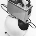
The Cordis CHECKMATE System1 consists of three components: (a) a nylon ribbon containing an array of 192Ir seeds, (b) a delivery catheter, and (c) a ribbon delivery device. The iridium seeds are 3 mm in length and 0.5 mm in diameter. The interseed spacing is 1 mm and the outer diameter of the nylon ribbon containing the seeds is 1 mm. The number of seeds in a ribbon can be altered to provide source lengths of 19 to 80 mm. Each 192Ir seed has an activity of about 33 mCi, thus making it possible to keep the treatment time within 15 to 25 minutes. The ribbon delivery device is mounted on a cart (Fig. 24.2) and uses a hand-crank mechanism to advance the ribbon into a closed-end delivery catheter.
Although the 192Ir source provides better dose homogeneity because of the lower depth dose gradient (ratio of surface to adventitial dose), its higher activity and γ-ray energy raise radiation protection concerns for personnel. Longer irradiation times and noncentering of the delivery catheter are other disadvantages of this device.
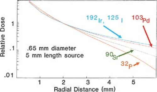 Figure 24.1. Radial dose falloff with distance for a number of sources. Doses are normalized to 1.0 at a radial distance of 2.0 mm. (From Amols HI, Zaider M, Weinberger J, et al. Dosimetric considerations for catheter-based beta and gamma emitters in the therapy of neointimal hyperplasia in human coronary arteries. Int J Radiat Oncol Biol Phys. 1996;36:913–921, with permission.) |
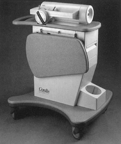 Figure 24.2. The Cordis CHECKMATE system showing delivery device on a cart. (From Ali NM, Kaluza GL, Raizner AE. Catheter-based endovascular radiation therapy devices. Vasc Radiother Monitor. 2000;2:72–81, with permission.) |
B.2. Guidant GALILEO
The Guidant GALILEO System2 uses a β source, 32P, for intravascular brachytherapy. The 32P source is hermetically sealed in the distal 27-mm tip of a flexible 0.018-inch nitinol wire. A spiral centering balloon catheter (Fig. 24.3), which centers the source wire, is flexible to navigate through
the arteries and also has perfusion capabilities to limit myocardial ischemia during the procedure. The source delivery unit is an automatic afterloader device that can be controlled from a remote location to advance and retract the source wire. A treatment-planning system is provided to calculate dwell times required to deliver the prescribed dose.
the arteries and also has perfusion capabilities to limit myocardial ischemia during the procedure. The source delivery unit is an automatic afterloader device that can be controlled from a remote location to advance and retract the source wire. A treatment-planning system is provided to calculate dwell times required to deliver the prescribed dose.
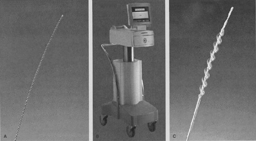 Figure 24.3. Guidant GALILEO system: A: source wire, B: source delivery unit, and C: spiral centering catheter. (From Ali NM, Kaluza GL, Raizner AE. Catheter-based endovascular radiation therapy devices. Vasc Radiother Monitor. 2000;2:72–81, with permission.) |
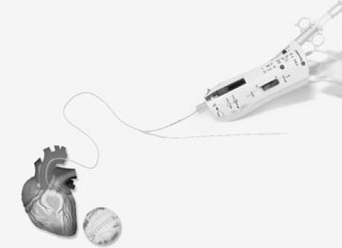 Figure 24.4. Novoste Beta-Cath system with source train and transfer device. (Courtesy of Novoste: www.novoste.com.) |
The major advantages of the system are the centering capability of the delivery catheter, automation of the afterloader, and availability of the treatment-planning system. The disadvantage is the rapid dose falloff radially, which is a characteristic of all the β sources.
B.3. Novoste Beta-Cath
The Novoste Beta-Cath System3 uses β sources of 90Sr/90Y isotope. It is a manual afterloader device with a catheter-based delivery system. The system consists of two main components: (a) a transfer device for housing and hydraulic delivery of a radiation source train and (b) a delivery catheter to transport the source train.
The delivery catheter (Fig. 24.4) has three lumens. The first lumen is used for travel of the guidewire. The second lumen is for transport of the source train consisting of sealed cylindrical seeds of 90Sr/90Y. The source train is delivered to the distal end of the delivery catheter by applying manual hydraulic pressure through a syringe, which contains sterile water and is attached to the transfer device. The third lumen, which is also attached to the transfer device, is designed to provide an opposite hydraulic pressure for returning the source train back into the storage position of the transfer device.
Major advantages of the Novoste system is its use of the 90Sr/90Y source, which is one of the highest-energy β emitters with a long half-life (28 years). Other advantages include high dose rate (treatment time approximately 5 minutes), patient and personnel safety, and simplicity of the handheld transfer device. The major disadvantage is the lack of a catheter-centering device, which could result in extreme dosimetric hot and cold spots within the target volume.
B.4. β-Emitting Liquid-filled Balloon
An alternative to catheter-based wires and seeds is to inflate the balloon dilation catheter with β-emitting radioactive liquid. The advantages of a liquid-filled balloon are inherent source centering and dose uniformity to the vessel wall. Several β-emitting isotopes such as 32P, 90Y, and 188Re, which can be obtained in a liquid radiopharmaceutical preparation, may be used in this technique.
The major disadvantages of liquid-filled balloons include (a) higher ratio of surface/adventitial dose compared to the catheter based γ-source systems and (b) the possibility, although remote, of balloon rupture and consequently leakage of radioisotope within the patient. Of the radioisotopes mentioned previously, the rhenium-188 formulation is preferable because of the reduced radiation dose to organs such as colon and thyroid due to its rapid renal elimination in the event of balloon rupture. 188Re also has a favorable maximum β energy (2.13 MeV).
One of the liquid-filled balloon devices was developed at the Columbia University/Oak Ridge National Laboratory (8). The system uses a liquid preparation of 188Re (188Re-MAG3), which is obtained at high specific activities from a tungsten (188W) generator and delivered into a perfusion
angiography balloon. A commercial system (RADIANT4) also uses a 188Re-filled balloon and is similar to conventional balloon PTCA (Fig. 24.5). It may be used before or after stent placement.
angiography balloon. A commercial system (RADIANT4) also uses a 188Re-filled balloon and is similar to conventional balloon PTCA (Fig. 24.5). It may be used before or after stent placement.
Related posts:

Stay updated, free articles. Join our Telegram channel

Full access? Get Clinical Tree


