Introduction: How to Use This Atlas

Chapter 1 Introduction


How to Use This Atlas


Interventional procedures are an integral component in the diagnosis and treatment of spine-related disorders. However, there is great variability with regard to how these procedures are performed and taught. The purpose of this atlas is to serve as a reference tool for a structured approach to fluoroscopically guided interventional spine procedures. This atlas is intended to be an adjunct to formal training in image-guided interventional spine care; it is not meant to be used in lieu of proper training with experienced mentors.


This introductory chapter will assist the reader in making the most of this atlas. With the use of disciplined principles and a consistent algorithmic methodology, interventional spine procedures can be performed more efficiently, accurately, and safely.


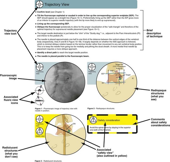
For each procedure, this atlas will provide relevant fluoroscopic images, anatomic diagrams, and photographs for the identification of appropriate landmarks in addition to a consistent set of fluoroscopic views throughout the atlas, which are denoted by the icons shown below. The “setup” for each technique will be demonstrated via the trajectory view, and multiplanar imaging will be emphasized. Ideal needle positioning before contrast injection, optimal and suboptimal contrast flow patterns or needle positions will be shown. Most importantly, safety issues, anatomic concerns, common pitfalls, and “tricks” will be highlighted.


Note: Please see page ii for a list of anatomical terms/abbreviations used in this book.


Fluoroscopic Views


image Trajectory View: “Setup Is Key”


The trajectory view, which is also known as the hubogram, hub view, needle view, down-the-barrel, or coaxial view, provides the initial orientation for needle placement and advancement. In this view, the interventionalist directly visualizes the needle’s path to the final target. Instead of estimating the needle’s trajectory, an unobstructed needle pathway is visualized, and an associated needle entry point is identified (Figure 1–1). An initial trajectory view can be identified for almost all procedures found in this atlas. The trajectory view is typically used only for initial setup and needle placement. On occasion, the trajectory view can also be one of the final multiplanar views.


The setup is obtained by appropriately positioning the fluoroscope relative to the patient. The fluoroscopic image produced with the use of this C-arm position will be depicted via the Trajectory View icon. The ease and timeliness of a procedure will be heavily dependent on an appropriate trajectory view setup.


For most trajectory and multiplanar images found in this atlas, a similar format will be used. The top left picture will be the actual fluoroscopic image. To the right, a drawing with radiopaque structures (that you can see) is outlined and labeled. On the bottom, a drawing with radiolucent structures (that you cannot see) is outlined and labeled. The needle and hub are green. When there is a “safety view,” the safety considerations are listed. In particular, lucent structures that should be avoided are shown and described.


To effectively use the trajectory view, the needle is placed parallel to the direction of the fluoroscopic beam (i.e., perpendicular to the image intensifier’s surface), and a coaxial image of the needle is obtained (Figure 1–2

Only gold members can continue reading. Log In or Register to continue

Stay updated, free articles. Join our Telegram channel

Dec 23, 2015 | Posted by in INTERVENTIONAL RADIOLOGY | Comments Off on Introduction: How to Use This Atlas

Full access? Get Clinical Tree

Get Clinical Tree app for offline access