Chapter 17 Introduction to ultrasound


 The sound waves are transmitted into the body and reflected back in varying amounts from an anatomical interface and these reflected waves are detected to produce an image.
 Modern ultrasound machines interpret the returning signals to generate images, which they send either to film or to a picture archiving communication system.


 Ultrasound is operator dependent and improper use of ultrasound techniques and equipment can lead to missed or misdiagnosis.
 Ultrasound studies include motion mode; spectral; colour and power Doppler; two-, three- and four-dimensional imaging.
 Although ultrasound has been in use for several decades with no proven evidence of damaging effects, high levels of ultrasound energy can cause bio effects in tissue; therefore prudent use of ultrasound is recommended.
 Ergonomics play an important part in minimising ultrasound work related disorders, especially affecting the upper limbs due to repeated movements, stretching and twisting.
 Training, quality assurance and audits are all important factors for maintaining high quality patient-focussed ultrasound examinations.
INTRODUCTION
Ultrasound was originally developed during World War I to track submarines as SONAR technology (Sound, Navigation And Ranging). Ultrasound was first used medically in the 1950s, with very early applications in fetal biometry; nowadays, it is used in just about every field of medicine. Furthermore, it is also now practised by a wide variety of professionals, in a multidisciplinary setting.
SOUND WAVES
Sound is a wave that is created by vibrating objects and propagated through a medium from one location to another, via particle interaction (Fig. 17.1). These particles move in a direction parallel to the direction of the wave; that is, longitudinally. Each individual particle pushes on its neighbouring particle and propels it in a forwards direction whilst restoring its original position at the end of the interaction. This backwards and forwards motion of particles in the direction of the wave creates regions of high pressure within the medium, where the particles are compressed together (compressions), and also regions of low pressure, where the particles are spread apart (rarefactions). The wavelength of sound is the distance between two successive high pressure pulses or two successive low pressure pulses.
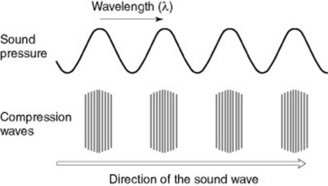
The frequency of a wave refers to how often the particles of the medium vibrate when a wave passes through it and is measured as the number of complete back-and-forth vibrations (cycles) of a particle of the medium per unit of time. The hertz (Hz) is a unit for frequency where 1 Hz is equivalent to one cycle per second. Humans can hear sound with frequencies of 20 to 20 000 cycles per second (i.e. 20–20 000 Hz).
ULTRASOUND
Ultrasound is high frequency sound beyond the hearing of the human ear. The frequencies of ultrasound required for diagnostic medical imaging are in the range 1–20 MHz. These frequencies can be obtained by using piezoelectric materials (particularly crystals). When an electric current is applied and reversed across a slice of one of these materials, the material contracts or expands. So a rapidly alternating electric field can cause a crystal to vibrate. These vibrations are then passed through any adjacent materials, or into the air as a longitudinal wave is produced – a sound wave (Fig. 17.2).
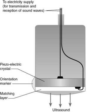
The piezoelectric effect also works in reverse. If the crystal is squeezed or stretched, an electric field is produced across it. So, if the ultrasound energy makes contact with the receiving crystal, it will cause the crystal to vibrate in and out and this will produce an alternating electric field. The resulting electrical signal can be amplified and processed in a number of ways. The piezoelectric effect occurs in a number of natural crystals, including quartz, but the most commonly used substance is a synthetic ceramic: lead zirconate titanate. The crystal is cut into a slice with a thickness equal to half a wavelength of the desired ultrasound frequency, as this thickness ensures most of the energy is emitted at the fundamental frequency.
Normally the transmitting and receiving crystals are built into the same hand-held unit, known as an ultrasonic transducer or probe. The transducer emits ultrasound in rapid pulses and also acts as a receiver most of the time.
It is important to note that the minimum interval between ultrasound pulses equals the time for the deepest echoes to return to the transducer, and the distance that each echo takes to return from the interface depends on the distance of the particular interface from the transducer and the speed of sound within that material. The thickness, size and location of various soft tissue structures in relation to the origin of the ultrasound beam are calculated at any point in time using this ‘pulse echo technique’.

The speed of sound itself varies from one material to another (Table 17.1) and is dependent on temperature, pressure and other factors.
Table 17.1 Speed of sound through various mediums
| Medium | Speed (m s−1) |
|---|---|
| Air | 330 |
| Water | 1497 |
| Fat | 1440 |
| Blood | 1570 |
| Metal | 3000–6000 |
| Soft tissue | 1540 |
Through electronic processing of the returning sound waves, a two-dimensional image can be created that provides information about the tissues and objects within the tissues. Real-time B-scans allow body structures that are moving to be investigated. This is done by allowing a rapid series of still pictures to be built up to capture the movement. The faster the frame rate, the quicker the image will be updated and the better the resolution of the image. More sophisticated systems have an array of transducers rather than just one pair of transmitter and detector.
Images can be then be displayed on a screen monitor (via what is known as a scan converter) and can be recorded on videotape, thermal paper, laser imaging or digitally on a picture archiving and communication system (PACs) or DVD. The thickness, size and location of various soft tissue structures in relation to the origin of the ultrasound beam are calculated at any point in time using this ‘pulse echo technique’.
ACOUSTIC IMPEDANCE
The strength of the reflected sound wave depends on the difference in ‘acoustic impedance’ between adjacent structures. The acoustic impedance of a medium is related to its density and the speed of sound through that medium (Table 17.2). The greater the difference in acoustic impedance between two adjacent structures, the more sound will be reflected, refracted or absorbed at their boundary rather than transmitted.
Table 17.2 Typical acoustic impedance of various mediums found in the body
| Medium | Acoustic impedance (in acoustic ohms) |
|---|---|
| Air | 0.000429 |
| Water | 1.50 |
| Blood | 1.59 |
| Fat | 1.38 |
| Muscle | 1.70 |
| Bone | 6.50 |
Example
Air and bone have such very different impedances to those of fat, muscle or water that a beam of ultrasound wave meeting bone or air is almost entirely reflected, refracted or absorbed; consequently there will be no transmission of sound beyond this layer. Similarly, air and skin have very different acoustic impedances; therefore a coupling medium is needed to match the impedance of the crystal in the probe more closely to the impedance of the skin of the patient and thus allow transmission of sound through the skin surface. The most common coupling medium, acoustic gel, is applied on the patient’s skin before an ultrasound examination. Coupling gel also has the advantage of reducing air bubbles between the skin surface and the transducer, thereby improving contact and minimising friction.
On the other hand, body layers such as fat, muscle and many body organs have very similar acoustic impedances, enabling most of the beam to pass from one layer into the next, with only a small fraction being reflected, and making this modality ideal for imaging soft tissue organs (Table 17.3).
Table 17.3 Different types of ultrasound scan
| Type of scan | How echo is received | Example of scan |
|---|---|---|
| A mode | Amplitude mode | Amplitude mode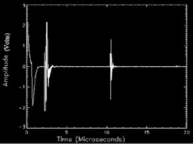 |
| Each layer producing a reflection shows up as a peak on the trace. The larger the echo, the higher the peak | ||
| B mode | Brightness mode | Musculoskeletal detail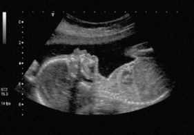 |
| Each reflecting echo is registered as a bright spot; the larger the amplitude of the reflecting echoes, the brighter the spots | ||
| M mode | Motion mode | Fetal pole (B mode) + waveform (M mode)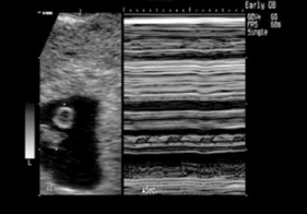 |
| Moving echoes are recorded to give traces of fetal heart pulsations |
ULTRASOUND ENERGY
There are two types of ultrasound energy used in diagnostics: continuous energy and pulsed energy.
DOPPLER ULTRASOUND
The Doppler effect was discovered by Christian Andreas Doppler (1803–1853) and is now commonly used in ultrasound imaging to examine the movement of liquids, such as blood flow in arteries and veins, allowing the location of blockages to be determined precisely. It is also used in fetal echocardiograms (ECG) in detecting and listening to the fetal heartbeat. Pulsed wave Doppler can also be used to evaluate blood flow through different structures and measure the velocity of the blood flow.
TRANSDUCERS
Ultrasound transducers, also called probes, come in different shapes, sizes and frequencies to allow use in different scanning situations (Fig. 17.3). For example, in an obstetric or upper abdominal scan the transducer used is known as a ‘convex-array’ or curvilinear transducer. This contour allows the transducer to be moved across the abdomen whilst maintaining good contact with the abdominal surface and also giving the wide field of view needed to see the upper abdomen or the whole fetus. Examples of Doppler studies are spectral, colour and power Doppler.
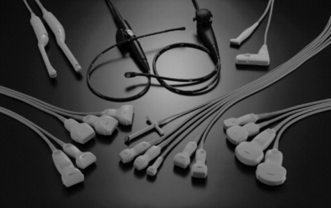
For thyroid, breast or musculoskeletal scans, a transducer with a flat surface – a ‘linear-array’ transducer – is commonly used.
In some applications, where the window to the organ of interest is small, transducers with a small footprint (i.e. the surface in contact with the patients) are used. These include:
Related posts:
Stay updated, free articles. Join our Telegram channel

Full access? Get Clinical Tree


