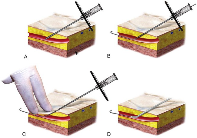
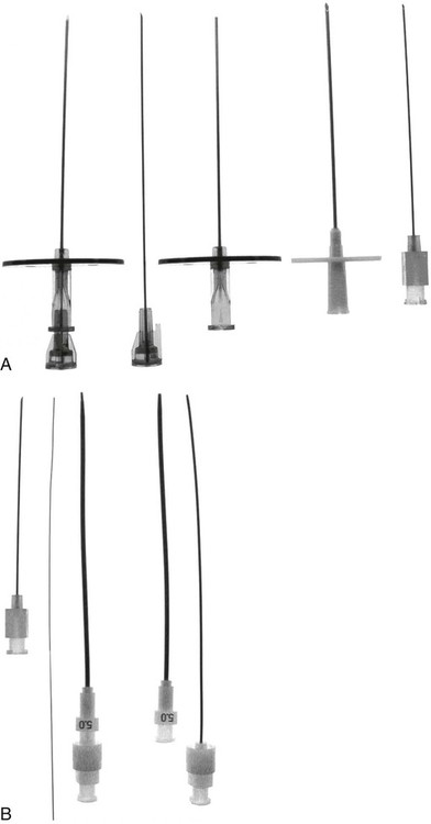
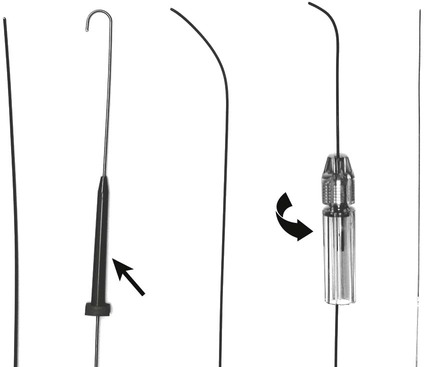
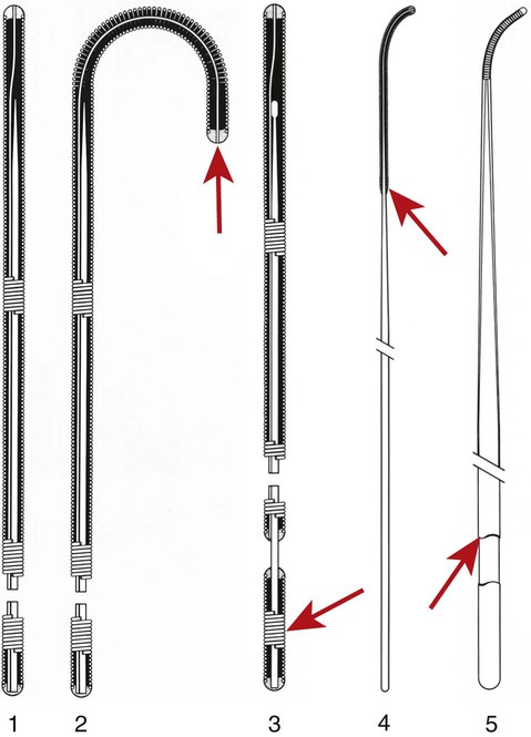
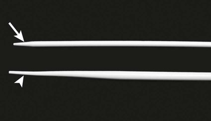
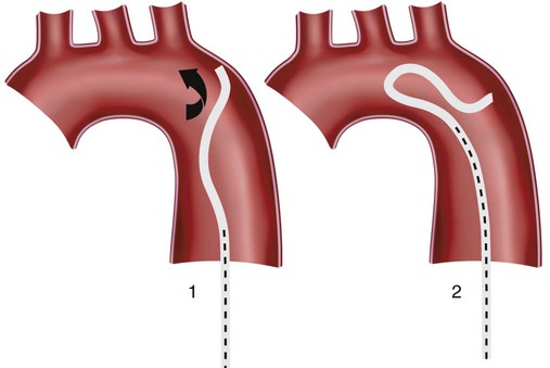
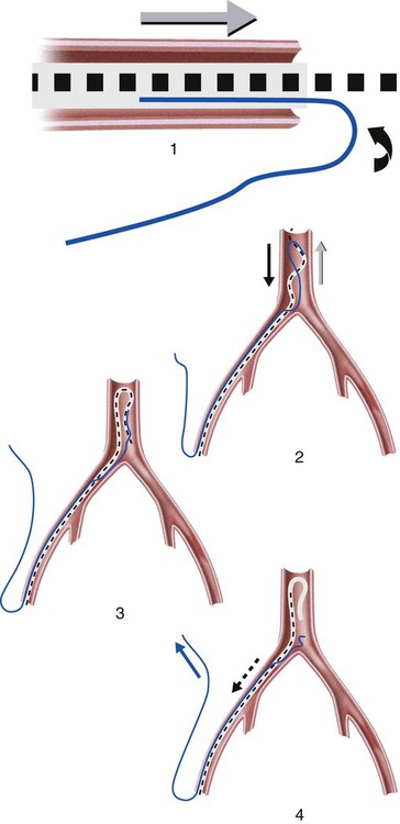
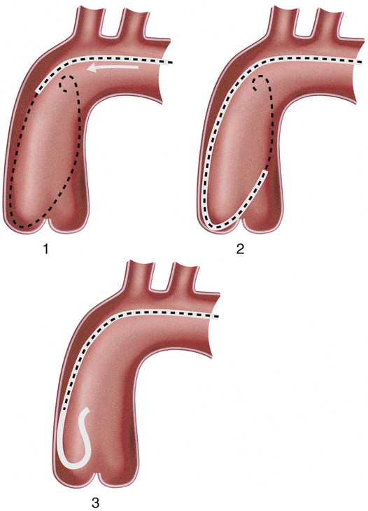
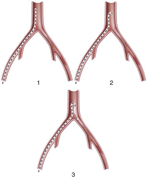
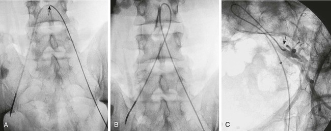
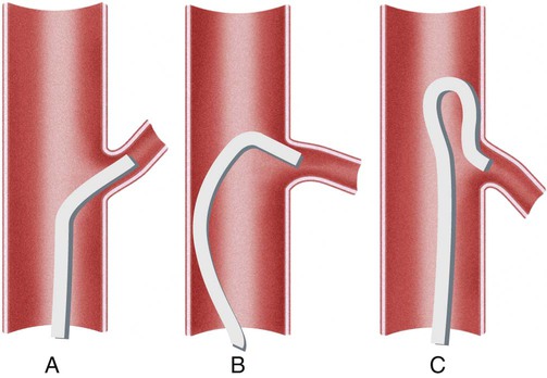
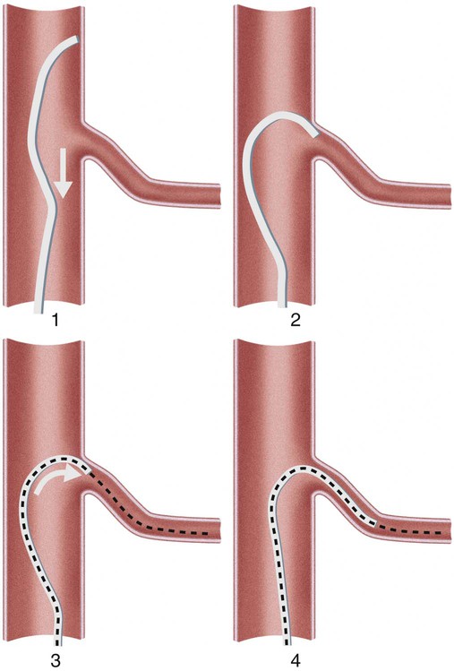
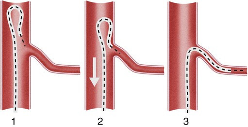
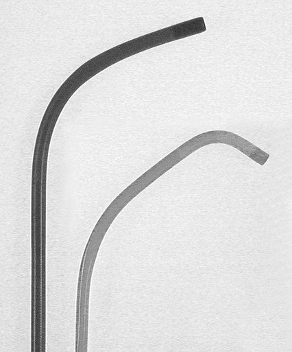
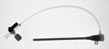
Invasive vascular imaging is based on the technique described by Sven Ivar Seldinger in 1953 (Fig. 3-1).1 This elegant innovation, now known by Seldinger’s name, eliminated the need for surgical exposure of a blood vessel before catheterization, thus allowing the transfer of angiography from the operating room to the radiology department. Virtually all vascular invasive procedures and devices use this technique. Patients should be well hydrated before the procedure.2,3 Outpatients should not be instructed to fast after midnight but encouraged to drink clear liquids until 2 hours before their scheduled appointment. In the preprocedural area, an intravenous infusion of 5% dextrose in 0.5% normal saline should be begun at 100 mL/h in normal patients. Fluid rates and characteristics should be adjusted in diabetics, patients on dialysis, and patients with congestive heart failure. Inpatients should have an established intravenous infusion in place before arriving in the angiographic suite. Most hospitals have established guidelines for oral intake before invasive procedures that must be followed, but remember that these are generally not designed for patients about to receive large doses of nephrotoxic contrast materials. There are no laboratory studies that are absolutely necessary before starting an invasive vascular procedure; most problems that can be predicted from abnormal laboratory studies occur after the catheter is removed (e.g., bleeding, renal failure). A low platelet count is the single most important predictor of postprocedural bleeding complications.4 The commonly acquired minimal laboratory studies are coagulation (international normalized ratio [INR], prothrombin time [PT], activated partial thromboplastin time [APTT], and platelet count) and serum creatinine value. Patients with renal failure undergoing central venous procedures that might entail intracardiac manipulation (e.g., central line placement) may require measurement of serum potassium concentration. Operator precautions against exposure to body fluids should be applied to all situations, even for patients with no known risk factors.5 Masks, face shields or other protective eye wear, sterile gloves, and impermeable gowns are the minimal measures. Closed flush and contrast systems decrease the risk of splash exposures. All materials used during the case should be disposed of in waste containers designed and labeled for biological waste. Radiation exposure to the patient and staff should be kept to a minimum.6 Use fluoroscopy only when needed to move catheters or guidewires. Prolonged fluoroscopy at high magnification with the x-ray tube in one position has been associated with radiation burns to the patient.7 Exposure can be reduced during long cases by use of pulsed fluoroscopy modes. The typical pulse rate of 15 pulses per second can be decreased by 50% or more with only a minor degradation in image quality. Ergonomic considerations are important during invasive vascular imaging. Many angiographers develop degenerative spine disease in the neck and back.8 Careful attention to the design of angiographic suites, especially the positioning of controls and monitors, can reduce twisting and bending. Similarly, patients should be positioned on the procedural table to minimize contortions on the part of the operator. The patient’s comfort also requires careful consideration. For long procedures, careful padding of pressure points, especially when the patient is under general anesthesia, is important. All angiographic procedures begin with a vascular access needle. There is great variety in vascular access needles, but all are designed to allow introduction of a guidewire through a central channel (Fig. 3-2). The simplest needle is a one-piece open needle with a sharp beveled tip. The guidewire is introduced directly through the needle once the tip is fully within the bleeding vessel lumen. This style of needle can be used for both arterial and venous punctures. Two-piece needles usually have a central sharp stylet that obturates the lumen and extends slightly beyond the needle tip. These needles have a blunted atraumatic beveled tip when the stylet is removed. The sharp stylet allows the needle to puncture the vessel, but once it is removed the risk of vascular injury from the blunt needle tip is theoretically removed. The stylet can be solid or hollow. In the latter case, blood may be visualized on the stylet hub once the vessel lumen is entered. With all styleted needles, the stylet must be removed to insert the guidewire. Needles with stylets are generally used only for arterial punctures. The most common sizes for vascular access needles of the type described above are 19 or 18 gauge in diameter and Guidewires are available in a number of thicknesses, lengths, tip configurations, stiffnesses, and materials of construction (Fig. 3-3). In general, the guidewire thickness (always referred to in hundredths of an inch—e.g., 0.038-inch) should be the same as or slightly smaller than the diameter of the lumen at the tip of the catheter or device that will slide over it. Guidewires that are too big will jam, usually at the tip of the catheter. However, if a guidewire is much smaller than the end hole of the catheter or device, there will be a gap between the guidewire and catheter that can cause vessel injury or prevent smooth movement over the guidewire. The most commonly used style of guidewire has a central stiff core around which is tightly wrapped a smaller wire, just like a coiled spring (Fig. 3-4). The outer wire is often welded to the core at the back end but not the tip. The purpose of the coiled outer wrap is to decrease the area of contact between the surface of the guidewire and the tissues. A fine safety wire runs along the length of the inside of the guidewire between the inner core wire and outer wrap and is welded to the outer wrap at both ends. This safety wire prevents the outer wrap from unwinding should the weld break. This is where the term safety guidewire originated. Vessel dilators are short, tapered, plastic catheters usually made of a stiffer material than diagnostic angiographic catheters (Fig. 3-5). The sole purpose of a dilator is to spread the soft tissues and the blood vessel wall to make introduction of a catheter or device easier. By inserting progressively larger dilators over a guidewire, a percutaneous puncture with an 18-gauge needle can be increased to almost any size. Sequential dilatation is important to minimize trauma to the vessel, since incremental steps in size (1F-2F) can be accomplished with much less resistance than one giant step. The initial dilator size after puncture with an 18-gauge access needle should be 5F. Larger dilators can follow as necessary. Dilatation of a puncture site beyond 50% of the expected diameter of the artery may obviate manual compression, because the muscular layer of the artery can no longer contract after removal of the catheter. Angiographic catheters are usually made of plastic (polyurethane, polyethylene, Teflon, or nylon). The exact catheter material, construction, coatings, inner diameter, outer diameter, length, tip shape, sidehole pattern, and endhole dimensions are determined by the intended use (Fig. 3-6). Catheters used for nonselective aortography are thick walled (to handle large-volume high-pressure injections) and often curled at the tip (the “pigtail,” which keeps the end of the catheter away from the vessel wall) with multiple side holes proximal to the curl (so the majority of the contrast medium exits the catheter in a cloud). Conversely, selective catheters are generally thinner walled with a single end hole because injection rates are lower and directed into a small vessel. Precise control of the movement of a selective catheter, especially at the tip, is important. These catheters usually have fine metal or plastic strands incorporated into the wall (“braid”) (Fig. 3-7). This results in a catheter tip that is responsive to gentle rotation of the shaft. Catheter outer size is described in French gauge (3F = 1 mm), whereas the diameter of the end hole (and therefore the maximum size of the guidewire the catheter will accommodate) is described in hundredths of an inch. The length of the catheter is described in centimeters (usually between 65 and 100 cm). The shape of the tip is named for either something the catheter looks like (“pigtail,” “cobra,” “hockey stick”), the person who designed it (Simmons, Berenstein, Rösch), or the intended use (celiac, left gastric, “head-hunter”) (see Fig. 3-6). There are so many different catheters that no one department can or should stock them all. The shape of some catheters (especially Teflon and polyethylene) can be modified by heating the catheter in steam while bending it into the desired configuration. Rapidly dunking the catheter into cool sterile water “sets” the shape. Complex catheter shapes must be re-formed inside the body after insertion over a guidewire. Any catheter will resume its original shape, provided there is sufficient space within the vessel lumen and memory in the catheter material. Some catheter shapes cannot re-form spontaneously in a blood vessel, particularly the larger recurved designs like the Simmons. There are a number of strategies for re-forming these catheters (Figs. 3-8 to 3-12). These same techniques can be used to create a recurved catheter from a simple angled selective catheter by forming a Waltman loop (Fig. 3-13).9 Selective catheters are chosen based on the particular vessel or anatomy that will be studied (Fig. 3-14). The technique used to catheterize a blood vessel with a selective catheter varies with the type of catheter (Figs. 3-15 and 3-16). The Waltman loop is particularly useful in the pelvis for selecting branches of the internal iliac artery on the same side as the arterial puncture. Guiding catheters are another class of catheters designed to make selective catheterization and interventions easier. These catheters can be used in some situations to help position and stabilize standard catheters. Guide catheters are nontapered catheters with extra-large lumens and a simple shape that accepts standard-sized catheters and devices (Fig. 3-17). They are used in circumstances in which standard catheters are difficult to position selectively. The larger outer catheter can provide direction and stability for the inner standard catheter. Guiding catheter size in French gauge refers to the outer diameter. This is the converse of the use of French sizes when describing standard catheters. The inner diameter of the guide catheter is usually described in hundredths of an inch, which must be converted to French gauge to determine which standard catheter will fit (1F = 0.012 inch = 0.333 mm). Most vascular interventions and diagnostic procedures are performed through vascular access sheaths. These devices of varying thickness and construction are open at one end and capped with a hemostatic valve at the other (Fig. 3-18). The intravascular end is not tapered, although the edges are carefully beveled to create a smooth transition to the tapered dilator used to introduce the sheath over a guidewire. The valved end usually has a short, clear side-arm that can be connected to a constant flush (to prevent thrombus from forming in the sheath) or an arterial pressure monitor. The purpose of the sheath is to simplify multiple catheter exchanges through a single access site. When not using a sheath, it is unwise to downsize catheters during a procedure (i.e., place a small catheter through a big hole in the artery) because of the risk of bleeding. Devices that are irregular in contour or even nontapered can be introduced through a sheath without fear of trauma to the device or access vessel. In some cases, a long sheath can straighten a tortuous access artery.
Invasive Vascular Diagnosis
Preprocedural Patient Evaluation and Management
Basic Safety Considerations
Tools
Access Needle
 to 5 inches in length.
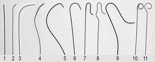
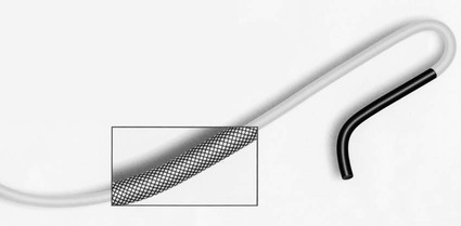
Guidewires
Dilators
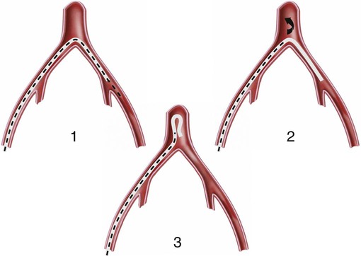
Catheters
Sheaths
![]()
Stay updated, free articles. Join our Telegram channel

Full access? Get Clinical Tree


Invasive Vascular Diagnosis