Lumbar Spine: Disc Disease and Stenosis
Clyde A. Helms
Imaging Methods
Imaging the lumbar spine for disc disease and stenosis has evolved in the past 20 years from predominantly myelography-oriented examinations to plain CT and MR examinations. Multiple studies have shown that myelography is not as accurate as CT or MR (1,2,3), yet myelography continues to be performed. Little justification exists for using a lumbar myelogram to determine disc disease or stenosis in this era.
Although few differences between CT and MR have been noted concerning diagnostic accuracy in the lumbar spine, MR will give more information and a more complete anatomic depiction than will CT. For example, MR can determine whether a disc is degenerated by showing loss of signal on T2WIs (Fig. 11.1). CT cannot provide this information. Whether or not this is useful information remains to be proved.
To achieve a high degree of accuracy, the proper imaging protocols must be observed. With CT scans, thin-section (3 to 5 mm) axial images should be obtained from the midbody of L3 to the midbody of S1 in a contiguous manner, i.e., no skip areas or gaps should be present (Fig. 11.2). One of the leading causes of failed back surgery is missed free fragments. Skip areas will often allow a free fragment to remain undiagnosed. Angling the gantry parallel to the end plates is not necessary, and image reformations are not helpful in the routine evaluation of disc disease and stenosis.
The MR imaging protocol is similar to that of CT in that thin-section axial images should be obtained from the midbody of L3 to the midbody of S1 (Fig. 11.3). Angling of the plane of imaging to be parallel to the end plates is not necessary, and contiguous images without skip areas are considered mandatory. Even though sagittal images will be obtained, free fragments and areas of stenosis are often seen on the axial images to better advantage than on the sagittal images (4). Other entities that can be overlooked if gaps are present in the axial imaging protocol include conjoined nerve roots, pars defects (spondylolysis), and lateral recess stenosis. These entities occur dorsal to the vertebral body, away from the disc level; thus, axial images limited to the disc level will not show them, and they may not be conspicuous on the sagittal images. In addition, spondylolysis (pars defects) can be overlooked if stacked axial images are not obtained, as they are often difficult to see on sagittal images (4).
Both T1WI (or proton density) and T2WI should be obtained in the sagittal and the axial planes. Attempting to shorten the study by foregoing one of the sequences is not recommended.
Disc Disease
Disc Protrusions. Terminology plays a large role in how radiologists describe disc bulges or protrusions. Since the advent of CT in the 1970s, disc bulges have been described by their morphology. A broad-based disc bulge has been said to be a bulging annulus fibrosus, and a focal disc bulge is a herniated nucleus pulposus. These interpretations are no more than 90% accurate. More significantly, most surgeons are not concerned with what name is applied to a disc bulge; they do not treat a bulging annulus differently than a herniated nucleus pulposus. They treat the patient’s symptoms and have to decide if the disc bulge is responsible for those symptoms. Most surgeons are satisfied with the terms “bulge” or “protrusion” added on to the term broad-based or focal (Fig. 11.4). Up to 50% of the asymptomatic population have disc protrusions (5); hence, just seeing a disc bulge on CT or MR does not necessarily mean it is clinically significant.
Both CT and MR have a high degree of accuracy in delineating disc protrusions and showing if neural tissue is impressed. MR can also show if annular fibers of the disc are disrupted by noting high signal on the T2-weighted images which disrupts the anulus. This has been termed a “high-intensity zone” or HIZ (Fig. 11.5). Although CT cannot be used to diagnose anular tears, clinicians treat anular tears the same way they treat protrusions with annular fibers intact.
Free Fragments. A type of disc protrusion critical to diagnose is the free fragment or sequestration. Missing free fragments is one of the most common causes of failed back surgery (6). The preoperative diagnosis of a free fragment contraindicates chymopapain, percutaneous discectomy, and, for many surgeons, microdiscectomy. At the very least, the presence of a free fragment means the surgeon must explore more cephalad or caudally during the surgery in order to remove the free
fragment. As free fragments can be very difficult to diagnose clinically, imaging is critical in the evaluation of the spine for any patient contemplating surgery. At times, it can be difficult to ascertain if a disc that has migrated cephalad or caudally is still attached to the parent disc or is really “free.” If the disc material is above or below the level of the disc space, whether it is attached really does not matter. Chymopapain and percutaneous discectomy would still be contraindicated, and many surgeons would not perform or, at the very least, would modify their microdiscectomy. The key element is recognizing that disc material is present away from the level of the disc space.
fragment. As free fragments can be very difficult to diagnose clinically, imaging is critical in the evaluation of the spine for any patient contemplating surgery. At times, it can be difficult to ascertain if a disc that has migrated cephalad or caudally is still attached to the parent disc or is really “free.” If the disc material is above or below the level of the disc space, whether it is attached really does not matter. Chymopapain and percutaneous discectomy would still be contraindicated, and many surgeons would not perform or, at the very least, would modify their microdiscectomy. The key element is recognizing that disc material is present away from the level of the disc space.
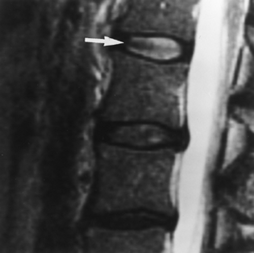 Figure 11.1. Desiccated Disc. A sagittal T2WI (TR, 4000; TE, 102) shows the L2–L3 and L3–L4 discs to be abnormally low in signal, indicating disc desiccation and degeneration. Compare with the normal L1–L2 disc (arrow), which has high signal. |
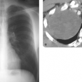
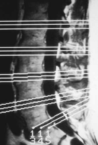 Figure 11.2. Inadequate Technique—Skip Areas. This MR scout film has cursors placed through the disc spaces. This allows large gaps or skip areas that can result in missed free fragments of discs. |
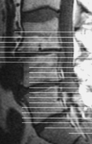 Figure 11.3. Proper MR Technique. This MR scout with cursors placed contiguously from the body of L3 to S1 allows complete coverage of the lower lumbar spine in the axial plane. |
Free fragments are diagnosed on CT by the presence of a soft tissue density with a higher attenuation value than the thecal sac which is located away from the disc space. A conjoined root (a normal variant of two roots exiting the thecal sac together; seen in 1% to 3% of the population [7]) (Fig. 11.6) or a Tarlov cyst (a normal variant referring to a dilated nerve root sleeve) can have a similar appearance to a free fragment on CT, but these will have attenuation values similar to the thecal sac. A conjoined root has a characteristic appearance on MRI (Fig. 11.6C).
Free fragments are diagnosed on MR by noting disc material that has moved away from the disc space (Fig. 11.7). Free
fragments migrate either cephalad or caudally, with no documented preference (8).
fragments migrate either cephalad or caudally, with no documented preference (8).
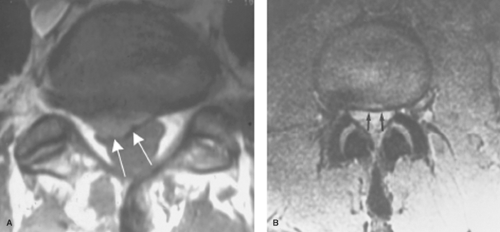 Figure 11.4. Disc Protrusions. Axial images show focal (A) (arrows) and broad-based (B) disc protrusions (arrows). Because these are both showing impression of the thecal sac, they could each cause symptoms.
Related posts:Stay updated, free articles. Join our Telegram channel
Full access? Get Clinical Tree
 Get Clinical Tree app for offline access

|