Mammography
5.1 Technique and Methods
5.1.1 Principles of X-ray Mammography
The term “X-ray mammography” (frequently just “mammography”) denotes the radiographic examination of the female (and also the male) breast. An X-ray mammography system consists of a X-ray tube with associated generator that produces the X-rays and a detector that captures the X-rays after they have passed through the breast. The technique uses low-energy ionizing radiation (“soft X-rays”). The exiting radiation after passing through the breast tissue projects an image of the breast onto X-ray film (in conventional mammography) or onto a detector (in digital mammography).
The detection of breast cancer by X-ray mammography is based on the greater X-ray absorption by cancerous tissue than by other intramammary structures. Approximately one-third of all breast cancers are associated with calcifications. Because calcifications absorb X-radiation almost completely, they are depicted clearly in radiographic examinations, making mammography the first-line examination for their visualization. Noncalcifying breast cancer masses also display strong absorption of ionizing radiation due to their very high cell density. Thus they can easily be identified within fatty breast tissue, which shows only moderate X-ray absorption. Because extremely dense glandular tissue structures have X-ray absorption similar to that of both benign and malignant proliferative lesions, these lesions are difficult or impossible to distinguish within such dense parenchyma.
Note
The main strength of X-ray mammography is the visualization of calcifications, which it detects very reliably. However, only 30% of all malignant breast cancers are associated with calcifications.
Breast cancers without calcifications can be difficult or even impossible to distinguish from dense glandular tissue structures. Almost half of all women in the age range that has a relevant breast cancer risk have high-density breast tissue (ACR [American College of Radiology] density types III and IV; ▶ 5.3.2).
5.1.2 Components of a Mammography System
Commercially available mammography systems contain the following components (▶ Fig. 5.1):
Generator.
X-ray tube.
Auxiliary filter.
Compression plates.
Antiscatter grid.
Automatic exposure control.
Detector system.
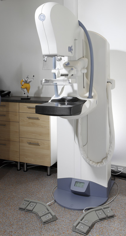
Fig. 5.1 Full field digital mammography system. Mammography device (from GE Healthcare, Milwaukee, WI, USA) with its main components: generator arm, X-ray tube, compression device, and detector (black).
X-ray Generator
The generator is required for delivering, modulating, and regulating the electrical energy required by the X-ray tube (cathode-heating current, tube current, anode drive, and automatic exposure control). The wave form (ripple) of the tube current as well as the generator power output help determine the radiation yield, exposure time, and image quality.
X-ray Tube
The X-ray tube is a vacuum tube containing electrodes that emit, accelerate, and decelerate electrons to produce X-radiation. The voltage applied between the electrodes (cathode and anode) accelerates the electrons (▶ Fig. 5.2). The anode material determines the characteristics of the radiation. Anodes used today are typically composed of two components: either molybdenum and rhodium, or molybdenum and tungsten. The point at which the electrons strike the anode is called the focal spot. For mammography the focal spot is smaller than that used in other radiographic examination techniques—just 0.3 mm for standard view images and 0.1 mm for magnification mammography.
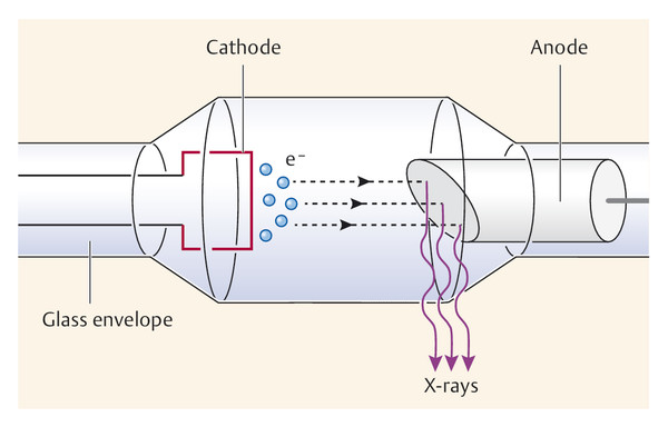
Fig. 5.2 Schematic diagram of an X-ray tube showing the cathode and anode. e−, electron.
Auxiliary Filter
Depending on the thickness and density of the breast, auxiliary filters are placed in the radiation path to modify the photon spectrum of the anode material and to optimize the radiation quality. Individual selection of the anode–filter combination can improve image contrast and reduce the radiation exposure (▶ Fig. 5.3). The most commonly used filter materials in mammography are molybdenum and rhodium. Copper and aluminum may be used in digital spectral mammography (see ▶ Fig. 5.21b).
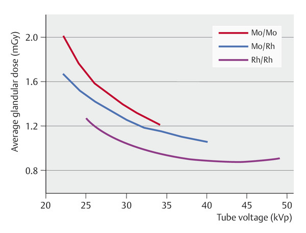
Fig. 5.3 Filter materials and anode–filter combinations. Effects of different anode–filter combinations (molybdenum–molybdenum, molybdenum–rhodium, rhodium–rhodium; the first term of each pair denotes the anode material and the second denotes the filter material) on the radiation exposure as a function of the tube voltage. Mo, molybdenum; Rh, rhodium.
Compression Plates
Appropriate compression of the breast is essential when performing a mammogram. The built-in compression plate in the mammography system can be adjusted manually or via a foot switch, and breast thickness and the pressure are shown on a display. Compression should be firm but not excessively uncomfortable; there is no standard value for optimum compression. Adequate compression during mammography provides the following advantages:
Reduced blur due to less scattering of radiation.
Improved contrast due to less beam hardening in the breast.
Reduced radiation dose.
Prevention of motion blurring.
Better image geometry.
Better tissue separation with reduction of superimposition effects, thus improving the resolution of the summation image.
Antiscatter Grid
Scattered radiation, usually simply called “scatter,” arises during mammography as a result of the interaction of radiation with breast tissue. Scatter can reduce image quality considerably. The negative effects on image quality are greatest when the breast is thick or breast tissue is dense. The deterioration in quality is seen primarily as a reduction in image contrast. For this reason, special soft-X-ray grids have been developed for use in mammography that reduce the relative proportion of scattered radiation to total radiation from approximately 45% to 15%. Typically, a linear grid is used, characterized by the grid ratio (height of the grid strips relative to distance between strips). The recommended grid ratio for mammography is in the range 4 to 5.
Note
An antiscatter grid does not prevent the scattering of radiation within the breast; rather, it reduces the amount of scatter that reaches the detector.
Imaging with a grid requires a higher dose of radiation than imaging without a grid, but the use of a grid improves image quality.
Automatic Exposure Control
Mammography systems have automatic exposure control to prevent incorrect exposure. Because breast composition varies greatly between individuals, the radiation dose required can vary by a factor of 4 to 5, even with objects of identical thickness. To calculate the optimum individual dosage in analog mammography, an automatic exposure control is placed below the detector to measure the incident dose. When the desired dosage has been reached, the exposure is terminated. In digital mammography systems, the optimum dosage is calculated from a test exposure at the beginning of the procedure. This pre-scan X-ray dose contributes to the required image acquisition dosage. On the basis of the test exposure the device automatically selects the suitable tube current and the optimum anode–filter combination for the breast being imaged in order to achieve optimal optical density, which should be between 0.6 and 2.2.
Detector System
For decades, film or film–foil systems were used for detection and visualization of X-radiation in analog mammography (see ▶ 5.1.5). Since the late 20th century, classic film–foil systems have been replaced first by fluorescent film materials, from which the image is read out and converted into digital data (indirect digital mammography), and, in a parallel development, by digital detectors that convert the X-ray intensities directly into digital data (direct digital mammography) (see ▶ 5.1.6).
5.1.3 Exposure Parameters
The most important exposure parameters selected for each individual breast examination are the tube current, measured in milliamperes (mA) and the tube voltage, measured in kilovolts (kV), which together determine the exposure time, measured in seconds (s). The combination of anode and filter materials, another important parameter, is automatically selected by the X-ray system.
Tube Current
The tube current represents the rate of emission of electrons by the cathode. These electrons are then accelerated toward the anode by the tube voltage. The tube current thus has a decisive effect on the radiation intensity and consequently on the optical density of the image. Both tube current (mA) and exposure time (s) have directly proportional effects on the radiation exposure and are often referred to in combination as the electric charge—the mAs product.
Tube Voltage
The tube voltage is defined as the electric potential across the X-ray tube between the cathode and the anode; it propels the electrons toward the anode. The higher the voltage applied, the faster the electrons are propelled. In mammography, low-energy, “soft” X-rays are used (25–35 kV) because intramammary tissues have only slight differences in absorption. In contrast, higher energy, “hard” X-rays (120 kV) are used, for example, for chest radiography to examine lung tissues.
Note
“Soft” X-rays (25–35 kV) are used in mammography. Such low-energy radiation is more hazardous, in terms of radiation biology, than high-energy or “hard” X-rays.
Exposure Time
Exposure time is the length of time the patient is exposed to radiation. Radiation exposure is directly proportional to both exposure time and tube current, and, as mentioned under Tube Current, are often referred to in combination as the electric charge, i.e., the mA s product. Recommended exposure times per image should not exceed 1.5–2 seconds.
5.1.4 Image Quality
Image quality is affected by physical-technical factors such as radiation quality, optical density, contrast, sharpness, noise, and resolution independently of the mammographic technique used (i.e., whether analog or digital) and physiological factors.
Radiation Quality
Because female breast tissue components have very similar absorption rates, mammography requires very high radiation quality to distinguish these components in varying shades of gray. Radiation quality is affected by generator ripple, anode and filter materials, the applied voltage level, and beam hardening in the breast.
Optical Density
The amount of density on a film produced by radiation is referred to as the optical density of the image. It is expressed as the log of the ratio of incident light intensity to transmitted light intensity. The recommended range of optical density (D) in mammography is from 0.6 to 2.2. Images with an optical density below 0.6 are underexposed (too light), while those with optical density above 2.2 are overexposed (too black). The linearity of the gradation curve in digital mammography allows postprocessing to shift the optical density of an image to a more favorable value. If the image is underexposed, postprocessing results in increased noise. Overexposed images, on the other hand, are well suited for readout after processing, but obtaining them will have exposed the patient to an unnecessary amount of radiation.
Contrast
Contrast is the difference in photographic density between image points with distinct optical densities. Image contrast essentially describes the difference in density between the darkest and lightest image points in the image (▶ Fig. 5.4). Image contrast is affected by:
Object contrast.
Beam contrast.
Film contrast.
It is essential to select the appropriate beam quality (determined by tube voltage plus anode–filter combination) to achieve optimum contrast. In digital mammography, contrast can be modified by subsequent image postprocessing.
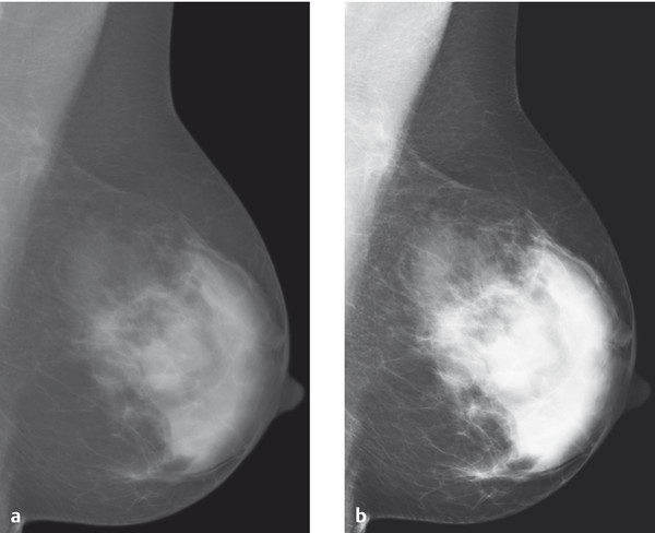
Fig. 5.4 Image contrast on the mammogram. Comparison of (a) low-contrast and (b) high-contrast mammographic images.
Note
The lower the tube voltage, the greater the resulting contrast in the radiographic image.
Sharpness
Sharpness refers to the visualization of an object with regard to its borders and size. An image is sharp when the change in optical density across the border between the object and its surrounding area is abrupt. Unsharpness (i.e., the lack of good spatial resolution) can be caused by a number of factors:
Geometric blur: This is dependent on the geometry of the X-ray beam. Sharpness increases with increase in focus–film distance, decrease in object–film distance, and decrease in the size of the focal spot.
Film–foil unsharpness: This is dependent on the blur caused by the film emulsion, due to limitations of the luminescent crystals in the intensifying screens, and due to cassette flaws. Film–foil unsharpness is not relevant in digital mammography.
Motion blur: This occurs primarily when the exposure time is too long, when the patient takes a breath, or due to an organ’s autonomous movement.
Noise
All variations in brightness information that are not due to the imaged object per se are generally attributed to what is called “noise.” Noise may be caused by a number of different factors; two in particular are:
Quantum noise: This results when the number of X-ray photons absorbed per unit surface area in the detector system is too low.
System noise: This results, for example, when the graininess of a film is too coarse (in analog mammography) or from deficiencies in the analog–digital conversion of digital mammography detector systems.
Noise affects image quality negatively and can reduce the detectability of small structures.
Resolution
The resolution of an image is defined and measured as the smallest distance between two details at which they can still be recognized as discrete structures. The limiting resolution of an image is reached when the smallest structures that can be distinguished as separate details are just visible. However, the resolution of such structures is possible only with sufficient contrast. Thus a distinction is made between resolution at high contrast (spatial resolution) and resolution at low contrast (contrast resolution):
Spatial resolution describes the smallest separation for a perceptible distinction between pairs of a black line and an adjacent white line, expressed as line pairs per millimeter (lp/mm). Once the lines become too fine, the line pairs cannot be distinguished because there is no perceptible difference in brightness between the black and white lines. Measurements have shown that the difference in brightness must be at least 4% (the so-called detectability threshold) to be perceived by the human eye.
Contrast transmission as a function of the fineness of line pairs (i.e., spatial frequency) is called the modulation transfer function, or MTF. The MTF is a useful measure of the true or effective resolution and allows a comparison of conventional imaging systems as a characteristic parameter of their image quality. In a comparison of different systems, however, and in particular when comparing analog and digital mammography systems, it is not sensible to use the limiting resolution as a criterion. Rather, the MTF should be compared within the range of 1.5 to 3.5 lp/mm, as only this range is relevant for analysis of mammograms.
Image quality is determined not by any single characteristic but rather through the interaction of various factors (▶ Fig. 5.5).
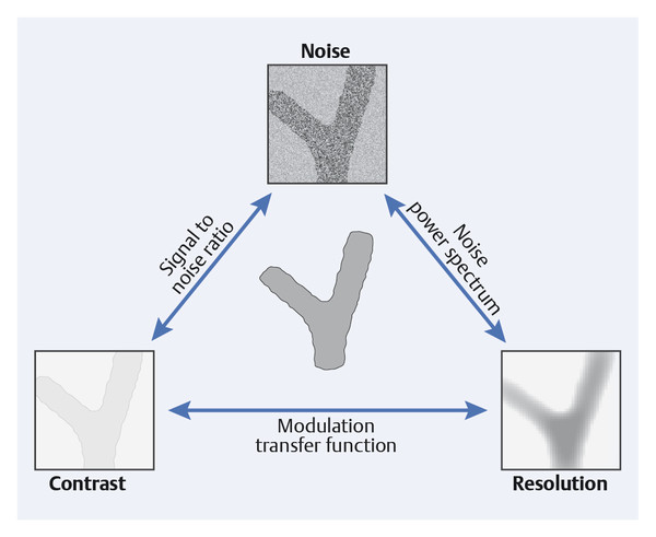
Fig. 5.5 Interaction of noise, contrast, and resolution in mammography. High image quality results from simultaneously achieving the lowest possible noise level, high contrast, and excellent resolution.
5.1.5 Analog Mammography
Film-Foil System; Development; Image Analysis
In the analog technique, the image-capture system used consists of a cassette with the mammographic film and intensifying screen enclosed within it. Film quality and processing have significant influences on the character and quality of the image. The films used are special orthochromatic films with high contrast and sensitivity. They are always used combined with an intensifying screen, which allows significant reduction in the radiation dose required (▶ Fig. 5.6). Fluorescent crystals, mounted on a thin carrier, are an essential component of the intensifying screen. Good intensifying screens are characterized by high intensification, high resolution, and minimal noise.
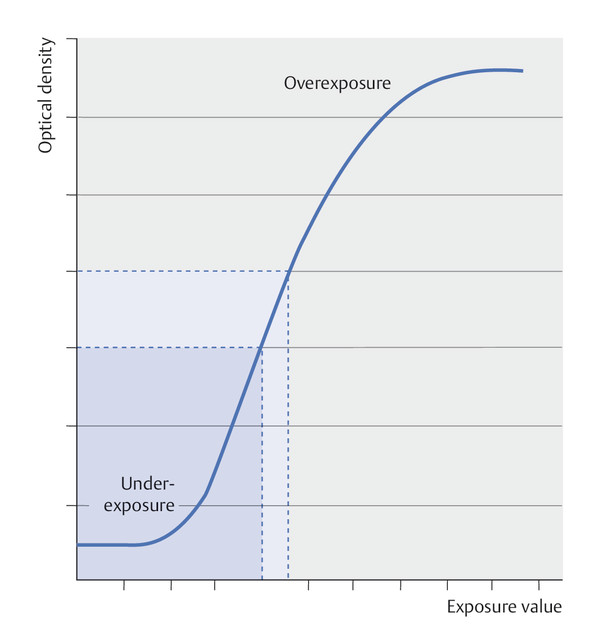
Fig. 5.6 Characteristic curve for conventional mammograms (film–foil systems). The characteristic curve for film–foil systems is sigmoidal. This is an example of an optical density curve. Image contrast is represented by the steepness of the curve. The lower portion of the curve indicates underexposure, while the upper portion indicates overexposure. The linear portion of the curve is the range that is useful for imaging.
Processing of conventional X-ray film involves steps of developing, fixing, rinsing, and drying. These are carried out as a standardized automated process in developing machines that apply the appropriate processing chemicals and maintain suitable temperatures for the requisite development times. Systems are available for use in darkrooms or for daylight processing.
Dedicated mammography viewboxes are available with various options and formats. Specific considerations for these relate to options for the viewing area, a uniform adjustable luminance of 2,000 cd/m2, and a supplemental high-intensity spot illuminator of more than 10,000 cd/m2.
Note
Persons responsible for reading mammograms should have their visual acuity checked annually.
Technical Quality Assurance
The goal of technical quality assurance is to achieve the highest possible diagnostic image quality with the lowest possible radiation exposure. Comprehensive quality assurance measures are described in the European Guidelines for Quality Assurance in Mammography Screening, and other standards for acceptance and constancy testing for mammography devices.
Acceptance Testing
Newly installed mammography systems are evaluated by the manufacturer or by an accredited testing facility. The following components are included in such an inspection:
Mammography unit.
Film processing.
Film cassettes.
Darkroom.
Film viewing facility.
Constancy Testing
Constancy testing is carried out at defined intervals for the various system components. The constancy of the conventional (analog) mammography unit is tested using mammographic phantom images. Other regularly tested components involve film processing and the darkroom (using a sensitometer and a densitometer), the film cassettes (using cassette testing grids), and film viewing (using a luminance meter).
The following test routines should be performed at the intervals specified:
Daily tests:
Constancy of the optical density (D = 1.2–1.6, exposure time <1 s).
Consistency of the film processing.
Exclusion of artifacts.
Position of the chest wall border of the beam field.
Weekly tests:
Resolution (>10 lp/mm) at the most commonly used focal spot.
Contrast resolution.
Image contrast.
Object and tube voltage pressure.
Monthly tests:
Optical density.
Exposure dose with automatic exposure.
Visual and functional testing of the mechanical adjustment aids.
Yearly tests:
Dose with manual exposure.
Object and tube voltage pressure for all tube voltages.
Spatial resolution of all foci.
Contrast resolution for all filters and anode material.
Correction switch for automatic exposure control.
Effective X-ray beam field using two cassettes.
Cassettes.
Darkroom.
Film-viewing conditions (viewboxes).
Pressure.
5.1.6 Digital Mammography
X-ray generation, positioning of the patient, and the required compression of the breast are the same in both analog and digital mammography. The significant development in digital systems is the replacement of the conventional film-exposure system by imaging plates, that is, indirect conversion detectors (for the indirect digital technique; offline) or digital detectors (for direct digital technique; online). The primary digital capture of image-relevant data allows separation of the steps of image acquisition, image processing, and image storage. The advantage of a digital imaging system is that each of these three steps can be optimized individually; in analog mammography, the film acting as detector serves simultaneously as detector, visualization medium, and storage medium.
A digital image is made up of a specific number of discrete image points, or pixels (picture matrix elements), which are arranged in a two-dimensional image matrix (grid). Each pixel is assigned a discrete gray-level value represented numerically. In a three-bit system, each gray value is saved as a sequence of three digits as a binary numerical value (quantification). The number of possible gray values for a digital image is termed the “image depth” (encryption).
Digital Systems
CCD Detectors
Charge-coupled device (CCD) detectors were the first digital detection systems in breast diagnostics. The basic principle is transformation of incident X-ray energy into light by means of a silicon scintillator medium; the light in turn can be encoded as digital image information. The size of the early CCD detectors was limited to about 5 cm by 5 cm, so that only small image field was possible— as used, for example, in stereotactic interventions.
Indirect Digital Full Field Mammography (Imaging Plate Technique)
In the early 21st century, imaging plates were developed for mammography that could be used as cassettes in conventional analog mammography devices. The incident X-ray photons excite electrons in the imaging plate to higher energy levels; when the plate is subsequently linearly scanned with a laser beam, the excited electrons return their original energy levels, emitting light (photons) as they do so. The photons are amplified by a photomultiplier and the light intensity is measured. Analog–digital transformation produces numerical digital values that in turn can be assigned grayscale levels.
The imaging plate technique is also called “cassette-based mammography” or “indirect digital mammography.” The imaging plate serves as a physical transfer medium between exposure and readout of the image data. This technique, rarely used now, represented an interim solution between analog mammography and direct digital full-field mammography.
Direct Digital Full Field Mammography (Detector Technique)
With the flat panel detector techniques in current mammography systems, the digital detector is wholly integrated into the system. The working principle of the detector is conversion of the incident X-ray energy into electrical signals that, after encoding as digital values, can be represented as a grayscale image. There are two different systems: those that employ a scintillator and those that do not.
Systems with a scintillator (CCD, amorphous silicon) convert X-ray energy primarily into visible light that is subsequently converted into an electrical signal.
Systems without a scintillator (amorphous selenium, photon counter) convert the X-rays energy directly into electrical signals within an optical semiconductor.
There is no significant difference in image quality or radiation exposure between the silicon-based and selenium-based imaging systems.
Mammography systems with integrated flat panel detectors are generally better than systems that use imaging plates. Ultimately, however, all systems that meet the national standards in accordance with acceptance testing for licensed mammography systems may be used without restriction.
CCD technology was also introduced worldwide for full field mammography in the form of slot-scan technology. In this, the breast is exposed to an X-ray beam from the radiation head and the detector system consists of multiple linearly arranged CCD chips—i.e., a line detector. Slot systems are no longer used.
Dynamic Range
Digital imaging systems show a greater dynamic range than conventional mammography film by a factor of about 100. This means that, in contrast to analog technology, with a sigmoid characteristic curve (▶ Fig. 5.6), digital systems exhibit a linear characteristic curve (▶ Fig. 5.7) so that grayscale images readable by the human eye can be constructed at incident doses much higher or lower than those available for analog mammography. The latitude in exposure in digital mammography is appreciably higher than in conventional mammography (▶ Fig. 5.8), practically eliminating incorrect exposure of mammographic images.
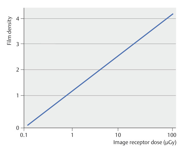
Fig. 5.7 Characteristic curve for digital mammograms. The characteristic curve of a digital imaging system is linear. The usable exposure range (linear component of the optical density curve) is much larger for digital systems than for conventional film–foil systems. This considerably reduces the risk of incorrect exposure in digital mammography.
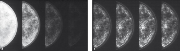
Fig. 5.8 Comparison of analog and digital phantom images at different exposures. (a) Conventional mammograms with underexposure, normal exposure, and overexposure (left to right). (b) Digital mammograms with underexposure, normal exposure, and overexposure (left to right).
Note
Digital mammography has a large dynamic range: as a result, image exposure is consistently very good.
Resolution
Theoretically, the pixel size of a digital detector limits the achievable spatial resolution. Imaging systems with a smaller pixel size enable a better depiction of small structures than systems with a larger pixel size (▶ Fig. 5.9). Digital imaging systems usually have a pixel size in the range 0.03 to 0.1 mm. Because the radiation dose per pixel must be the same to maintain constant image quality, systems with smaller pixel size require a larger dose than those with a larger pixel size.
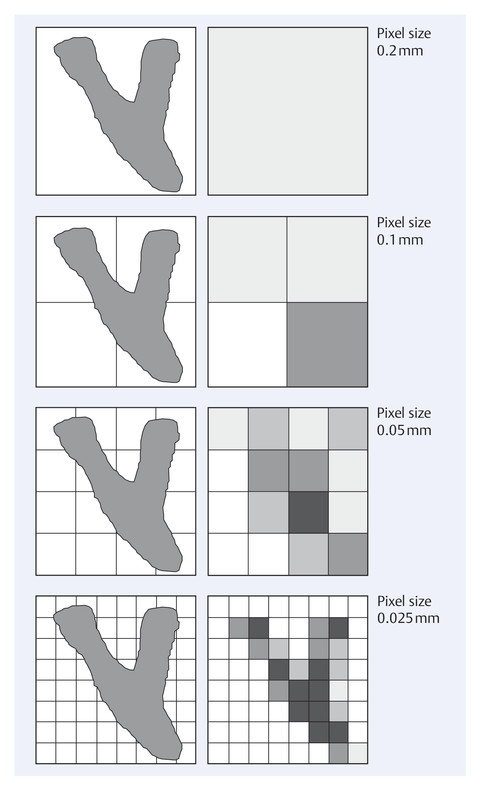
Fig. 5.9 Imaging of small structures as a function of pixel size. Comparison of images of small structures using detector systems with different pixel sizes.
There is now ample evidence that spatial resolution (pixel, lp/mm) per se is not the decisive criterion in evaluating the imaging properties of a digital mammography system. Other criteria, such as signal-to-noise ratio and contrast, play much more decisive roles in the reliable recognition and evaluation of relevant structures in digital mammography (see ▶ Fig. 5.5).
Effective Detective Quantum Efficiency
The effective detective quantum efficiency (eDQE) has arguably proved to be the most reliable measure used to evaluate the imaging characteristics of a digital system. It is a measure of how effectively the information contained in the X-ray intensity pattern that is generated by the X-rays that penetrate the breast is ultimately transmitted onto the mammogram (▶ Fig. 5.10). The quality of the radiation, the dose, and, naturally, the spatial frequency all influence the eDQE.
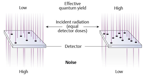
Fig. 5.10 Effective quantum yield in digital mammography.
Ultimately, the eDQE most reliably represents the parameters of image quality and dose efficiency, although there is no standardized method to determine the effective detective quantum efficiency.
Note
Digital mammography makes an image available on the monitor in a very short time.
Digital mammography allows image optimization using digital image postprocessing.
Digital mammography facilitates archiving (PACS: Picture Archiving and Communication System) and communications (teleradiology).
Screen Image Assessment
Digitally acquired primary data sets permit image analysis on the monitor (▶ Fig. 5.11). For the assessment of digital mammograms, special demands are placed on the spatial resolution and brightness of suitable monitors, which are described in the PAS (publicly available specification) (see ▶ Technical Quality Assurance).
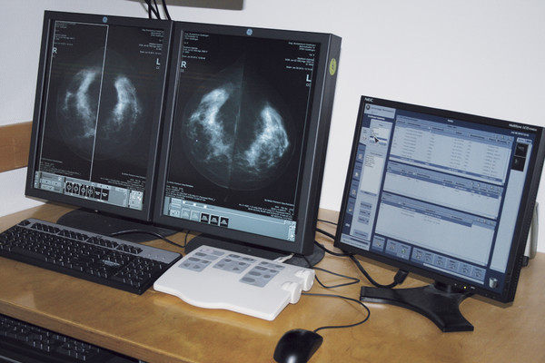
Fig. 5.11 A workstation for evaluation of digital mammograms.
Image Postprocessing
Image information in primary digital form has the advantage of being adaptable to a wide range of options in subsequent image processing. The image provides no new information, but the available image information may be better visualized in some instances. Basic adjustment by the viewer of the image on the monitor is usually all that is required, however, so that specific postprocessing of the data is only occasionally carried out.
Numerous options are available for image postprocessing. Probably the most commonly used are changing the contrast, changing the brightness level (▶ Fig. 5.12), inversion (▶ Fig. 5.13), zooming (▶ Fig. 5.14), image subtraction, and metric quantification (▶ Fig. 5.15) of the structures of interest.
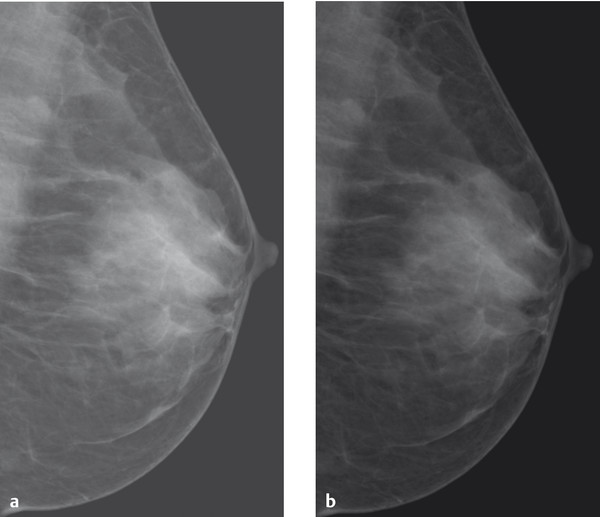
Fig. 5.12 Brightness variations. Mammograms rendered with different brightness levels. (a) High brightness level. (b) Low brightness level.
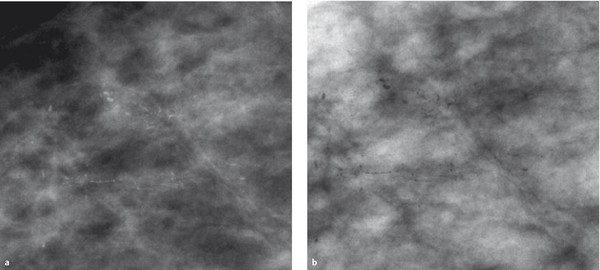
Fig. 5.13 Inversion. Presentation of microcalcifications (a) in a conventional grayscale image and (b) in an inverted image.
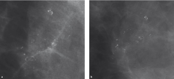
Fig. 5.14 Zooming. Microcalcifications in a mammogram. (a) Zoomed view of calcifications from the original digital full-field image.(b) Magnification mammography of the same microcalcifications.
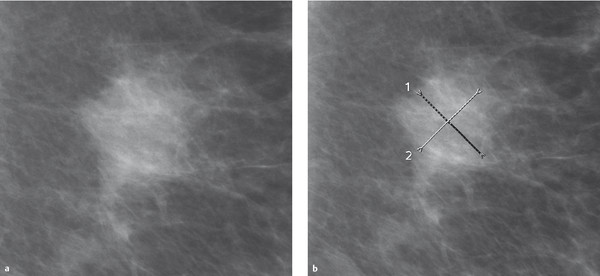
Fig. 5.15 Metric quantification. (a) Mass lesion in the mammogram. (b) Diameter measurements are made along perpendicular lines.
Computer-aided Diagnosis
Computer-aided detection (CADe) and computer-aided diagnosis (CADx) systems (usually lumped under the term CAD) are available to the image interpreter as supplementary tools for image evaluation. CADe combines elements from artificial intelligence with digital image processing. It is based essentially on highly complex pattern recognition, whereby microcalcifications and mass lesions that are typically indicative of malignancy are identified and tagged on the mammogram. As a rule, several thousand images are required to optimize a suitable algorithm. CADe systems are usually restricted to identifying and marking conspicuous structures and areas (detection: ▶ Fig. 5.16). The application spectrum is broadened by CADx systems that are reported to be able to characterize findings, not only marking conspicuous structures but also giving them an assessment.
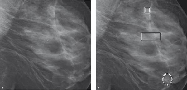
Fig. 5.16 Mammograms with CAD marking. (a) Digital mammogram. (b) Computer-aided detection marks calcifications within rectangles and masslike densities within circles.
Experience has shown that CAD systems identify and tag microcalcifications on the mammogram with a high degree of reliability (high sensitivity), but that the number of false positive markings for mass lesions is very high (low specificity).
At present, CAD systems cannot replace human mammographic interpretation. As supplemental input after completion of image interpretation by the human evaluator it can be helpful in detecting potentially overlooked calcification patterns.
Tomosynthesis
The biggest limitation of X-ray mammography is the poor detection of noncalcified breast cancer in the dense, highly glandular breast (ACR density types III and IV). In these cases, the sensitivity of the procedure, whether analog or digital, falls to 30 to 40%. This is because the similarity of the X-ray absorptivity of carcinomas and that of the surrounding mammary tissue makes it difficult or impossible to differentiate a tumor within dense parenchyma.
One approach to solving this problem is digital tomosynthesis. In the technique of digital breast tomosynthesis (DBT), single, nonoverlapping slice images are synthesized after capture of multiple images from different imaging angles (▶ Fig. 5.17).
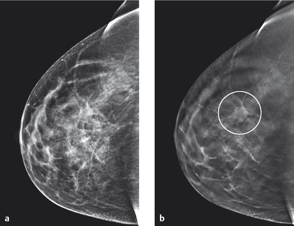
Fig. 5.17 Example of tomosynthesis. Improved visualization of architectural distortion (circle in [b]) in the center of the right breast in tomosynthesis, as compared to reconstructed 2D digital images. (a) Reconstructed 2D image. (b) Tomosynthesis: single slice image.
(Images courtesy of Andrew Smith, Hologic, Medicor.)
With the imaging systems currently in use, typically 11 to 25 individual digital images are captured at approximately 5° intervals as the tube moves in an arc over a total segment of 15 to 60° (▶ Fig. 5.18). The detector remains stationary as it receives the incident X-rays, and a series of nonoverlapping single slices with a limited depth of field are computed by digital processing software. Because a series of slices at different depths and with different thicknesses can be reconstructed from the same acquisition, radiation exposure is kept down to the dose for a single digital mammography projection image.
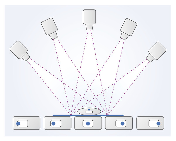
Fig. 5.18 The principles of tomosynthesis. Multiple images of the breast are taken from different angles. Images of intramammary structures show different positions relative to the detector due to parallax.
Characteristic parameters for digital tomosynthesis are:
Detector resolution, which basically determines the resolution within each individual slice.
Scan angle, which defines the resolution between the individual slices.
Number of captured images as a measure of the scan duration and the cumulative dose.
At present there are no definitive recommendations for setting parameters. Both the number of captured images and dosage issues are subjects of discussion. In addition, there is no standard recommendation for the combined use of projection mammography and complementary breast tomosynthesis.
Breast Volume Computed Tomography
Dedicated computed tomography (CT) for the examination of the female breast essentially represents development of 2D tomosynthesis into the third dimension (3D tomosynthesis). Here the radiographic imaging of the breast takes place in a cylindrical cavity with an X-ray tube on one side and a detector opposite the tube; rotation of this assembly around the subject enables a 3D radiographic representation in thin slices (▶ Fig. 5.19).
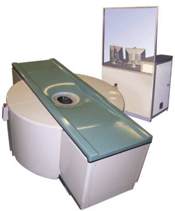
Fig. 5.19 Breast CT system.
(Image courtesy of Koning Corporation, New York, NY, USA.)
The CT examination is carried out separately for each breast. Acquisition of isotropic voxels permits distortion-free secondary reconstruction of the acquired data sets at any desired level and in any view (▶ Fig. 5.20).
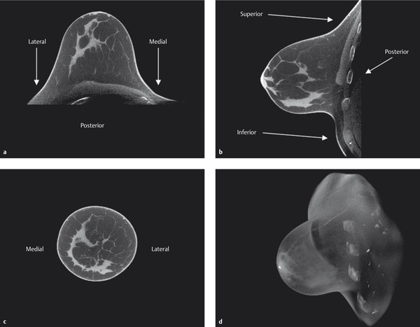
Fig. 5.20 Representative breast CT images. Right breast. (a) Transverse view. (b) Sagittal view. (c) Coronal view. (d) 3D reconstruction of the dataset.
(Images courtesy of Koning Corporation, New York, NY, USA.)
Contrast-Enhanced Mammography
Contrast-enhanced digital mammography (CEDM) techniques represent a promising approach for the early detection of breast cancer because they deliver both the information of a classical mammogram and additional information pertaining to the perfusion of intramammary structures. CEDM employs the subtraction technique, which is familiar from the dynamic breast MRI procedure, as well as a spectral mammography technique in which mammographic images are captured at two different X-ray energy levels.
Contrast-Enhanced Subtraction Mammography
For contrast-enhanced subtraction mammography, mammograms are performed sequentially with identical breast positioning, before and after the peripheral venous administration of an iodine-containing contrast agent. The precontrast images are subtracted from the images after administration of contrast to visualize the contrast-enhancing areas.
Disadvantages of this technique are the number of mammograms that must be performed (4–7 per breast) with the associated total radiation dose, and the breast compression, which needs to be applied with adequate pressure over a period of at least 3 minutes. Also, with this technique only one breast can be examined per administration of contrast agent. While this technique did indeed serve as a forerunner for further developments, all of these factors taken together ultimately explain why it is no longer in use today.
Contrast-Enhanced Spectral Mammography
Contrast-enhanced spectral mammography makes use of the absorption discontinuity of iodine at a specific voltage (33 keV, known as its K-edge). Use of appropriate filter materials (rhodium and molybdenum, and also aluminum and copper) enables nearly simultaneous capture of low-energy (low-dose) and high-energy (high-dose) mammographic images (▶ Fig. 5.21). Computational processing with dedicated algorithms visualizes intramammary areas showing increased iodine uptake.
In contrast-enhanced spectral mammography, one or two low-energy (25–30 kV) and one or two high-energy (ca. 55 kV) images per breast are captured (dual energy), beginning approximately 2 to 3 minutes after the peripheral venous administration of an iodine-containing contrast agent. The low-dose images have the same image characteristics as a mammogram and can be interpreted in the same way. The algorithm-processed image provides additional information and makes the iodine-enhancing structures appear bright (▶ Fig. 5.22). The high-dose image serves only for calculating the algorithmic image. It does not provide any direct diagnostic information.
The use of contrast-enhanced spectral mammography has been shown to provide an improvement in sensitivity. It may be possible not to take the second image projection because obscuring overlapping parenchymal structures are not relevant with this technique. This would have the advantage of reducing the radiation exposure by about 40%.
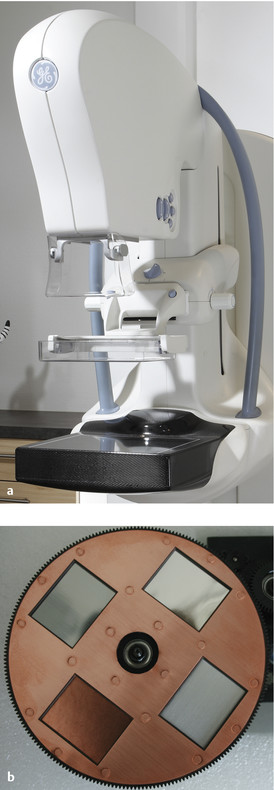
Fig. 5.21 Contrast-enhanced spectral mammography with a selection of filters. (a) A mammography device with option for contrast-enhanced spectral mammography. (b) Filter holding four different filter materials.
(Image [a]: GE Healthcare, Milwaukee, WI, USA.)
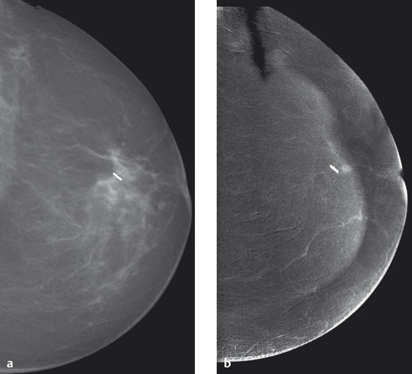
Fig. 5.22 Contrast-enhanced spectral mammography of a small retromamillary carcinoma. (a) A conventional mammogram after breast-conserving surgical treatment for breast cancer with a clip marking the tumor bed. There are no other conspicuous features. (b) Contrast-enhanced spectral mammography shows a 4-mm enhancing focus directly ventral of the clip. Tumor recurrence was verified histologically.
Synthesized 2D Image from Tomosynthesis
In a development of tomosynthesis, a reconstructed 2D image can be generated from the tomosynthesis dataset. The availability of such a reconstructed, or synthesized, 2D image simplifies comparison with previous digital summation images and has advantages over direct comparison of the tomosynthesis slice images with the summation image. ▶ Fig. 5.23 shows an example of a synthesized 2D image reconstructed from the tomosynthesis dataset compared with the corresponding conventional digital mammogram.
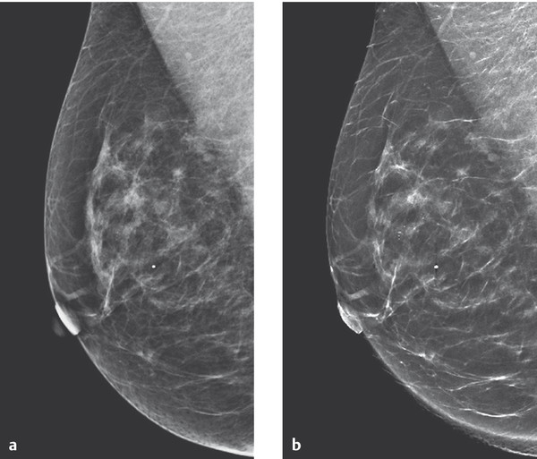
Fig. 5.23 Digital mammogram compared with tomosynthesis mammogram. Comparability of the images is good. There is better visualization of the intramammary microcalcifications in the synthesized 2D image compared with digital reconstructed image. (a) Digital summation image. (b) Tomosynthesis reconstructed 2D-image.
(Images courtesy of Andrew Smith, Hologic, Medicor.)
Technical Quality Assurance
The quality of digital mammography depends to some extent on different factors from those determining the quality of analog mammography; accordingly, criteria for and test phantoms used in technical quality assurance in analog mammography are not appropriate for the technical quality assurance of digital mammography systems. Prominent experts in the field collaborated to compile a Publicly Available Specification (PAS) that regulates the requirements for digital mammography devices (generator and image reception system) and the accessories used (scanners, image display devices, networks, CAD systems, archiving, etc.). In addition, testing procedures have been developed for all components.
The central requirement of PAS 1054 includes the proviso that analog film–foil systems and digital devices must achieve the same image quality. This is measured by the contrast-detail resolution, which can be tested by the ability for the reliable imaging of gold leaves in a CDMAM (contrast detail mammography) phantom (▶ Fig. 5.24). A dedicated test phantom for digital mammography was also developed for testing other imaging characteristics (▶ Fig. 5.25).
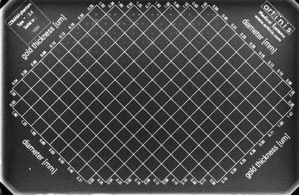
Fig. 5.24 Contrast detail mammography (CDMAM) phantom. Radiographic image of a CDMAM phantom with visualization of inserted gold disks that vary in diameter and thickness.
(From Artinis Medical Systems, Zetten, Netherlands.)
Related posts:


Stay updated, free articles. Join our Telegram channel

Full access? Get Clinical Tree


