Medical Imaging Informatics


Medical Imaging Informatics


In healthcare, medical informatics represents the process of collecting, analyzing, storing, and communicating information (data) that is crucial to the provision and delivery of appropriate patient care critical for health and well-being, as well as for education and research. These data are comprised of many sources such as doctors’ notes in free-form text, quantitative and qualitative measurements of various basic tests including blood evaluations, electrocardiograms, projection radiographs, more complex tests such as genetic surveys, CT, MRI, PET, and other advanced evaluations. Informatics has grown substantially over the past decade to address the issues of uncertainty in handling data by converting analog input sources to digital format and ensuring an authoritative source for patient demographics and records through the implementation of digital databases and the electronic health record (EHR). Advances in computer networks and access to the Internet provide rapid mechanisms for acquisition, archiving, retrieval, concurrent sharing, and data mining of relevant medical information.

Medical imaging informatics is a sub-field of medical informatics that addresses aspects of image generation, processing, management, transfer, storage, distribution, display, perception, privacy, and security. It overlaps many other disciplines such as electrical engineering, computer and information sciences, medical physics, and perceptual physiology and psychology, and has evolved chiefly in radiology, although other specialties including pathology, cardiology, dermatology, surgery—in fact, the majority of clinical disciplines—generate digital medical images as well. Certainly, imaging informatics is an important and growing part of health and medicine.

An important part of imaging informatics includes ontologies (the basic communications lexicons), standards (critical pathway to ensure interoperability of different informatics systems), computers and networking (the information highway and communication medium), and the picture archiving and communications system (PACS) infrastructure (image distribution, analysis, diagnosis, and archive). PACS implementation details, including operational considerations, image display technology/calibration, and quality control issues, constitute the largest section of this chapter. The lifecycle of a radiology exam from the initial order to report distribution and action by the referring physician demonstrates the imaging informatics infrastructure and use cases necessary to achieve the goals of patient-centric care. Privacy and Security, Big Data and Data Plumbing, image and non-image analytics, business aspects of informatics, and the wider description of clinical informatics complete the topics covered in this chapter.


5.1 ONTOLOGIES, STANDARDS, PROFILES


5.1.1 Ontologies

An ontology is a collection of content terms and their relationships to represent concepts in a specific branch of knowledge; relevant to this book are those for medical imaging. Different levels of usage include the definition of a common vocabulary, the
standardization of terms and concepts, schemas for transfer and sharing of information, representation of knowledge, and the structures for constructing queries and their responses. Benefits of ontologies include enhancing interoperability between information systems; facilitating the transmission, reuse, and sharing of structured content; as well as integrating knowledge and data. There are many ontologies found in the field of medicine and medical imaging for the electronic exchange of clinical health information. SNOMED-CT (Systematized Nomenclature of Medicine—Clinical Terms) is a standardized, multilingual vocabulary of clinical terminology that is used by physicians and other health care providers supported by the National Library of Medicine within the United States Department of Health and Human Services. In the United States, it is designated as the national standard for additional categories of information in the EHR and health information exchange transactions. It allows healthcare providers to use different terms that mean equivalent things when implementing software applications. For instance, myocardial infarction (MI), heart attack, and MI are interpreted as the same issue by a cardiologist, but to software, these are all different. SNOMED-CT enables semantic interoperability and supports the exchange of normalized clinically validated health data between different providers, researchers, and others in the healthcare environment. Resources include subsets to identify the most commonly used medical codes and terms. This can assist in identifying diseases, signs, and symptoms for subsequent classification, as explained in the next paragraph.

The International Statistical Classification of Diseases and Related Health Problems (ICD), is sponsored by the World Health Organization and is in its tenth revision (ICD-10). This is a manual that contains codes for diseases, signs and symptoms, abnormal findings, and external causes of injury or disease. Individual countries use the ICD-10 coding for reimbursement and resource allocation in their health systems and to develop their own schemas and strategies. In the United States, variant manuals developed by the Centers for Medicare and Medicaid Services (CMS) are called ICD-10 Clinical Modification, (ICD-10-CM) with over 69,000 diagnosis codes and Procedure Coding System (ICD-10-PCS) with over 70,000 procedure codes for inpatient procedures. The ICD-10 content is used to (1) assign codes for procedures, services, conditions, and diagnoses for categorizing conditions and diseases; (2) form the foundation for health care decision making and statistical analysis of populations; and (3) bill for services performed in the hospital inpatient setting.

The Current Procedural Terminology (CPT) is a medical code manual published by the American Medical Association, used to describe the procedures performed on the patient during the interaction including diagnostic, laboratory, radiology, and surgical procedures. Physicians bill and are paid for services performed in a hospital, office setting, or other places of service based on these codes. Often, human coding teams or automated software tools assist in the verification and validation of codes for specific procedures for reimbursement. These codes are more complex than the ICD codes and are typically updated yearly.

In radiology, specific medical terminology and vocabularies are used to describe the anatomy, procedures, and protocols used in day-to-day diagnosis of medical images; however, there are many procedure names and descriptions that are practice-specific. For instance, one group may call a procedure a thorax CT angiogram, while another may call the same procedure a chest CTA. To faithfully exchange health information requires a common terminology to ensure accurate recording and to enhance consistency of data to facilitate medical decision support, outcomes analysis, and quality improvement initiatives. Since 2005 the Radiological Society of North America (RSNA) has gathered radiology professionals and standards organizations to generate a radiology-specific lexicon of terms called RadLex (Radiology Lexicon),
and a RadLex Playbook that assigns RPID (RadLex Playbook IDentifier) tags to those terms (RSNA, 2020a). RadLex has been widely adopted in radiology and for use in registries, such as the American College of Radiology (ACR) Dose Index Registry (DIR). By providing standard names and codes for radiologic studies, the playbook facilitates a variety of operational and quality improvement efforts such as workflow optimization, radiation dose tracking, and image exchange. A more widely adopted and broader standard that covers tests and measurements in many medical domains is called LOINC (Logical Observation Identifiers Names and Codes), initiated in 1994 by the Regenstrief Institute, a distinguished medical research organization part of Indiana University. A harmonized effort to unify these ontologies has been established by both sponsors to use LOINC codes as the primary identifiers for radiology procedures (LOINC, 2019). A more comprehensive and widely adopted vocabulary standard will assist in making radiology procedure data more accessible to clinicians when and where they need it.


5.1.2 Standards Organizations

The acquisition, transfer, processing, diagnosis, and storage of medical imaging information is a complex process—no single system in an Information Technology (IT) environment can provide all the functionality necessary for safe, high quality, accurate, and efficient operations. Information systems must, therefore, share data and status with each other. This requires either proprietary interfaces (expensive to implement, difficult to maintain, and tightly controlled by the vendor) or IT standards, which are consensus documents that openly define information system behavior. The American National Standards Institute (ANSI) is the United States organization that coordinates standards development and accredits Standards Development Organizations (SDOs) as well as designates technical advisory groups to the International Organization for Standardization (ISO). In healthcare, two of the most important SDOs are Health Level 7 (HL7) and the National Electrical Manufacturers Association (NEMA). Standards, as applied to medical imaging informatics, have evolved over the years through consultation and consensus of key stakeholders, including manufacturers of medical imaging equipment, manufacturers of medical data software and systems such as the Radiology Information System (RIS), EHR (also known as the electronic medical record—EMR), PACS, professional societies, and end-users who participate, contribute, and update the standards content to ensure interoperability and communication amongst healthcare information systems and devices. Standards define communications protocols, structures, and formats for textual messages, images, instructions, payload deliveries, transactions, and a host of other information for technical, semantic, and process interoperability. IT standards relevant for imaging include Internet standards, the HL7 standard, and the Digital Imaging and Communications in Medicine (DICOM) standard.


5.1.3 Internet Standards

Computer networking and the Internet are successful because of hardware, protocol, and software standards that have been developed by the Internet Engineering Task Force (IETF) of the Internet Society (https://www.internetsociety.org). The Internet is the global system of interconnected computer networks that use the Internet protocol suite transmission control protocol/Internet protocol (TCP/IP) to link devices worldwide. There are many Internet standards relevant to imaging. HyperText Transfer Protocol (HTTP) is an application protocol for distributed, collaborative hypermedia
information systems, and is the foundation of data communication for the World Wide Web, one of many application structures and network services foundational to the Internet. HyperText Markup Language (HTML) is the standard markup language for documents designed to be displayed in a web browser. Uniform Resource Locator (URL), also known as a web address, specifies the syntax and semantics for location and access of resources via the Internet. Network Time Protocol (NTP) is used to synchronize clocks in computer systems so that messages are interpreted in the appropriate time frame. Simple Mail Transfer Protocol (SMTP) and Internet Message Access Protocol (IMAP) are the basis for email transactions on the Internet. Multipurpose Internet Message Extensions (MIME) protocol allows extension of email messages to include non-textual content including medical images. Transport Layer Security (TLS) and its predecessor Secure Sockets Layer (SSL) define cryptographic mechanisms for securing the content of Internet transactions. The Syslog Protocol is used to convey event notification messages for audit trail and logging purposes. Extensible Markup Language (XML) is a free, open standard for encoding structured data and serializing it for communication between systems and is the method of choice for most new standards development for distributed systems.


5.1.4 DICOM

DICOM is a set of standards-based protocols for exchanging and storing medical imaging data, as actual images and text associated with images. Managed by the Medical and Imaging Technical Alliance (MITA), a division of NEMA, it is structured as a multi-part document and its Parts are numbered as listed in Table 5-1
(DICOM, 2020). Understanding how these Parts relate to one another is key to navigating the DICOM Standard, as it now constitutes many thousands of pages. (For example, one may refer to a “Part 10 file” as Part 10 defines DICOM file formats.) DICOM is recognized by the International Organization for Standardization as the ISO 10252 standard. DICOM is an open, public standard, and information for developing DICOM-based software applications is defined and regulated by public committees and is now, practically speaking, universal for image exchange for medical imaging modalities. Ever evolving, the standard is maintained in accordance with the procedures of the DICOM Standards Committee through working groups (WGs), standard development processes, public comment, and WG approvals. Proposals for enhancements or corrections (CPs) may be submitted to the Secretariat. Supplements and corrections to the Standard are balloted and approved several times a year. When approved as final text, the change is official and goes into effect immediately. Vendors creating devices or software claiming to support the DICOM standard are required to conform to strict and detailed protocol definitions and must provide documentation of the specific DICOM services and data types supported in a DICOM Conformance Statement as defined by Part 2 of the Standard. DICOM is critical to interoperability and communication of medical imaging and associated data between medical imaging systems and imaging databases. Essentials of DICOM use are covered in Section 5.4.


TABLE 5-1 PARTS OF THE DICOM STANDARDa


The structure of the DICOM standard is divided into parts 1-21.


Part 1: Introduction and Overview


Part 2: Conformance


Part 3: Information Object Definitions


Part 4: Service Class Specifications


Part 5: Data Structures and Encoding


Part 6: Data Dictionary


Part 7: Message Exchange


Part 8: Network Communication Support for Message Exchange


Part 10: Media Storage and File Format for Media Interchange


Part 11: Media Storage Application Profiles


Part 12: Media Formats and Physical Media for Media Interchange


Part 14: Grayscale Standard Display Function


Part 15: Security and System Management Profiles


Part 16: Content Mapping Resource


Part 17: Explanatory Information


Part 18: Web Services


Part 19: Application Hosting


Part 20: Imaging Reports using HL7 Clinical Document Architecture


Part 21: Transformations between DICOM and other Representations


aNote: DICOM Parts 9 and 13 are now formally rescinded and no longer available.


With the widespread and growing use of the Internet, one area of increasing attention is to the development of web-based tools and Application Programming Interface (API) designs for DICOM, called DICOMWeb—the DICOM standard for web-based medical imaging, consisting of services defined for sending, retrieving, and querying for images and related information. The intent is the provision of a web-browser friendly mechanism for storing, querying, and accessing images using REST (representational state transfer) architectural styles for hypermedia systems and RESTful interfaces so that the applications can be simple, lightweight, and fast.


5.1.5 HL7

HL7 refers to a set of international standards for the exchange, integration, sharing, and retrieval of electronic health information that supports clinical practice and management, delivery, and evaluation of health services. HL7 International is the ANSI-accredited organization for developing HL7 standards. Its high-level goals are to develop coherent, extendible standards that permit structured, encoded healthcare information to be exchanged between computer applications and to meet real-world requirements. The domains that the standard covers are extensive, and the interoperability is achieved through messages and documents. There are two versions of HL7 in current use. Most health systems use HL7 Version 2 (now up to V2.8.2) for their data, which is a version developed in the 1980s before the Internet became mainstream. HL7 is cryptic to the uninitiated, although it is required training in informatics as it is the ubiquitous standard for automated textual information exchange in healthcare IT. Although an exhaustive discussion of HL7 is beyond the scope of this text, one should be familiar at least with the three most common message types as they pertain to the imaging chain, respective to PACS: (1) ORU—Results; (2) ORM—Orders; (3) ADT—Admission, Discharge, and Transfer. Two of the common segment types are also important: (1) OBR—Observation Request; and (2) OBX—Observation/Result.

A comprehensive list of message types and segments (HL7, 2007) and general information regarding HL7 can be found at the HL7 website (HL7, 2020). Sample HL7 messages and segments are shown in Section 5.4, Lifecycle of a Radiology Exam.


HL7, compared to DICOM, is much less formally structured (thus allowing tremendous flexibility, but also creating the need to redefine almost every implementation explicitly). As a result, a major amount of effort in healthcare is devoted to the development, documentation, and maintenance of HL7 interfaces. HL7 integration engineering represents a significant fraction of the technical work in healthcare informatics overall, and work is under way to attain a more general model of interoperability.

HL7 Version 3, initiated in 1995 with a formal standard available in 2005, is based on object-oriented principles and XML encoding syntax for messaging, including processes, tools, and rules for the unambiguous understanding of code sources and domains that are being used. Clinical Document Architecture (CDA) is an XML-based markup standard to specify encoding, structure, and semantics of clinical documents for exchange that are human-readable. In the United States, a further restraint on the CDA standard is termed the Continuity of Care Document (CCD), which requires a mandatory textual part for easy interpretation, and a structured part to provide a framework for using coding systems such as SNOMED and LOINC.

Like DICOMWeb, a development in the HL7 community is a new standard called Fast Health Interoperability Resources (FHIR—pronounced “fire”) and based on modern web services and RESTful interfaces approach that uses APIs and openstandard file formats such as XML or JSON (JavaScript Object Notation) to store and exchange data. FHIR can fill the needs of the previous HL7 standards (V2, V3, CDA) and provides additional benefits in the ease of interoperability, interfaces, and access to data.


5.1.6 IHE

Integrating the Healthcare Enterprise (IHE) was founded by the RSNA in 1999 and joined by the Healthcare Information Management and Systems Society (HIMSS) soon thereafter. Now, IHE International consists of over 150 member organizations including professional societies, SDOs, government agencies, industry, and academic centers. IHE does not generate IT standards but promotes their use to solve specific complex problems of healthcare information system interoperability and develops “integration profiles” that describe the details of the proposed standards-based solutions. There are many “domains” in which the IHE is organized, similar to a clinical enterprise, such as Radiology, Cardiology, Patient Care Coordination, Patient Care Devices, Pathology and Laboratory Medicine, etc. New domains are added as fields of healthcare adopt the IHE process. Two committees responsible for the work product within a domain are the Planning Committee to strategize the direction and coordination of activities from proposals received, and the Technical Committee to develop an integration profile that describes the specific problem, the standards used to solve the problem (e.g., HL7 and DICOM), and the specifics of the solution. After review within IHE, the integration profile is released for public comment, comments are received/reviewed, and then the profile is tested in a “connectathon,” which is a vendor-neutral, monitored testing event. After appearing in the connectathon, the profile is then incorporated into the technical framework of that domain.

For Radiology, there are many integration profiles such as scheduled workflow (SWF), patient information reconciliation (PIR), production and display of mammography images (MAMMO), radiation exposure monitoring (REM), and cross-enterprise document sharing of images (XDS-I). For instance, the latter profile is important in ensuring the proper transfer of medical data and images across enterprises and businesses. Vendors claiming conformance to IHE technical frameworks must provide an integration statement that specifies which IHE actors (the units of functionality) are
provided and in which integration profiles they participate. Purchasers of medical imaging equipment can use conformance to the IHE technical framework as a contractual obligation and as an effective shorthand in a request for purchase document that avoids the complexities of specifying standards and methods to achieve a given interoperability. A major benefit of the IHE integration profiles is that a single integration profile can require conformance with DICOM, HL7, and other standards. A commitment by a vendor to support that integration profile will commit the vendor to conforming to the various standards included in that single integration profile. Verification of successful interoperability requires quality control testing, as described in Section 5.3.9—PACS Quality Control.


5.2 COMPUTERS AND NETWORKING


5.2.1 Hardware

Computer hardware includes the physical parts or components of a computer, such as the power supply, cooling fans, case, and motherboard. The motherboard is the main component, with integrated circuitry and backplane connectors that connect all other parts of the computer, including the central processing unit (CPU), graphics processing unit (GPU), random access memory (RAM), graphics, network, and sound cards, expansion cards, and storage devices (both fixed and removable) for temporary or permanent storage. Input and output peripherals are housed externally to the main computer and include a mouse and a keyboard, touchpad (for laptop computers), webcams, microphones, speakers, display monitors, and printers.

The configuration and capability of a computer are important considerations to ensure performance and throughput requirements for a radiologist workstation with the need to view large images and large datasets quickly and efficiently. The CPU processing performance is increased by using multi-core processors (from 2 to 16 and more) on one CPU chip by handling asynchronous events, interrupts and using simultaneous multi-threading to share actual CPU resources. Clock speed governs how fast the CPU can execute instructions and is measured in gigahertz (GHz)—typical values are between 1 to 5 GHz. The GPU is a specialized electronic circuit designed to rapidly manipulate and accelerate the manipulation/processing of images by processing large blocks of data in parallel, making them much more efficient than CPUs in doing such tasks. RAM stores the code and data that are being actively accessed by the CPU and GPU modules. With medical images and ever-expanding sizes and amount of image data, a configuration of a minimum of 16 GB RAM and perhaps 32-64 GB and greater is recommended, depending on the applications of a particular system to ensure that an entire study with relevant prior studies and multiple applications (PACS, RIS, Reporting, EHR, etc.) can be available without having to send information back and forth from slower data access on solid-state or spinning disk storage media. Size and type of computer storage media must be configured with enough capacity, typically in the multi-terabyte range, and network card bandwidth (e.g., 1 Gb/s or higher) must be matched to avoid bottlenecks in data transfer. Portable storage devices such as universal serial bus (USB) drives and Secure Digital (SD) cards use flash memory—a non-volatile computer memory storage medium that can be electronically erased and re-programmed, offering fast read and write access times (although slower than RAM). These storage devices offer capacities in the 100s of gigabyte range, with many exceeding terabytes.


5.2.2 Software and Application Programming Interface

Software refers to the programs, consisting of sequences of instructions, which are executed by a computer. Software is commonly categorized as application programs or systems software.

An applications program, commonly referred to as an application, is a program that performs a specific function or functions for a user. Examples of applications are e-mail programs, word processing/presentation programs, web browsers, image display, and speech recognition programs.

System software is designed to run on computer hardware and as a platform for other software. It refers to the files and programs that make up the computer’s operating system (OS), such as Microsoft Windows, Mac OS, and Linux Ubuntu. System files contain libraries of system services, functions, device drivers, system preferences, and many other configuration files. The system software is the interface between the hardware and specific user applications to manage memory, input/output devices, internal and peripheral devices, system performance, and error messages. Driver software makes it possible for connected components to perform their intended tasks as directed by the OS. Such components include a keyboard, mouse, display card, network card, and soundcard. Firmware is operational software embedded within a memory chip for the OS to identify and run commands to manage and control activities of any single hardware component. The most important firmware is the BIOS (Basic Input/Output System) or UEFI (Unified Extended Firmware Interface) on a motherboard. This loads first as a computer is powered up to wake up all hardware (processor, memory, disk drives) and to run the bootloader to install the OS.

Programming language translators are intermediate programs called compilers, assemblers, and interpreters. They allow software programmers to translate high-level language source code that humans can understand, such as Java, C+ +, and Python, into machine-language code that computer processors can understand. Machine code is written in a number system of base 2, with either a 0 or a 1 representing an “onoff” switch called a “bit” at a computer memory location, and typically sequenced in 8-bit chunks called a byte. A word is the largest unit of data that can be addressed on memory (i.e., register size). Expressed in bits, the size of word with which a processor can handle data in average consumer laptop computers today is 32 to 64 bits.

Utility software is a type of system software that sits between the OS and application software and is intended for computer diagnostic and maintenance tasks. Examples include anti-virus, disk partition, file compression/defragmentation, and firewall algorithms to ensure optimal function and security of the computer.

System services and libraries are a specific API to provide access to tools and resources in an OS that enables developers to create software applications by specifying how software components can access and leverage aspects of the OS. An API defines the correct way to request services from an OS or other application and expose data within different contexts and across different channels. Private APIs have specifications for a specific company’s products and services that are not shared, public or open APIs can be used by any third party without restrictions, and partner APIs are used by specific parties that have a sharing agreement. They are also classified as local, web, or program APIs. Local APIs offer OS services to application programs to provide database access, memory management, security, and network services. An example is the Microsoft.NET framework. Web APIs are designed to represent resources like HTML pages and addressed using the HTTP protocol; thus, any web URL activates a web API. Web APIs are often called REST or RESTful because the publisher of the REST interface does not save data internally between requests. This allows many users to request information independently and intermingled, similar
as they are on the Internet. Simple programming tools or even no programming at all can be used for data access using the REST model. When APIs need to communicate between different nodes on a network, a mechanism called a Remote Procedure Call (RPC) can be employed, as well. Modern Operating Systems provide a rich set of remotely accessible system services. An extension to provide security and fully distributed software components is part of a broader Service Oriented Architecture (SOA). SOA refers to architectures designed with a focus on services. Begun in the 1990s, the classic approach of SOA architectures was based upon complex services to build complex systems. SOA has evolved to encompass microservices, which represent a more recent subset by implementing applications as a set of simple independently deployable services using modern JavaScript. Web services and RESTful interfaces are also under the umbrella of SOA.


5.2.3 Networks and Gateways

Computer networks permit the transfer of information between computers, allowing computers to enable services such as the electronic transmission of messages (e-mail), transfer of computer files, and use of distant computers. Networks, based upon the distances they span and degree of interconnectivity, may be described as local area networks (LANs) or wide area networks (WANs). A LAN connects computers within a department, a building such as a medical center, and perhaps neighboring buildings, whereas a WAN connects computers at large distances from each other. Most WANs today consist of multiple LANs connected by medium or long-distance communication links. The largest WAN in aggregate is the Internet itself.

Networks have both hardware and software components. A connection must exist between computers so that they can exchange information. Common connections include coaxial cable, copper wiring, optical fiber cables, and electronic connections such as radio wave and microwave communication systems used by Bluetooth and Wi-Fi communication links. Optical fiber cables have several advantages over cables or wiring carrying electrical signals, particularly with long-distance connections, including no electrical interference, lower error rates, greater transmission distances without the need for repeaters to read and retransmit the signals, and highest transmission rates. The benefit of wireless communication systems such as Wi-Fi is the freedom from hard-wired connections, although transmission rates are typically lower than a direct connection. Software components are also required between the user application program and the hardware of the communications link, necessitating network protocols for communication and provision of services. Both hardware and software must comply with established protocols to achieve successful transfer of information.

In most networks, multiple computers share communication pathways. Network protocols facilitate this sharing by dividing the information to be transmitted into packets. Some protocols permit packets of variable size, whereas others permit only packets of a fixed size. Each packet has a header containing information identifying its destination. Large networks usually employ switching devices to forward packets between network segments or even between entire networks. Each device on a network, whether a computer or switching device, is called a node, and the communications pathways between them are called links. Each computer is connected to a network by a network adapter, also called a network interface, installed on the I/O bus of the computer, or incorporated on the motherboard. Each interface between a node and a network is identified by a unique number called a network address. A desktop computer usually has only a single interface, but a server generally has
multiple interfaces to facilitate redundancy and throughput management. A switching device connecting two or more networks may have an address on each network.

The maximal data transfer rate of a link or a connection is called the bandwidth, a term originally used to describe the data transfer capacities of analog communications channels. An actual network may not achieve its full nominal bandwidth because of overhead or inefficiencies in its implementation. The term throughput is commonly used to describe the maximal data transfer rate that is achieved. Bandwidth and throughput are usually described in units of megabits per second (106 bps = 1 Mbps) or gigabits per second (109 bps = 1 Gbps). These units should not be confused with megabytes per second (MBps) and gigabytes per second (GBps)—recall that a byte consists of eight bits. Note that the raw network bandwidth must also accommodate overhead from various protocols (packet framing, addressing, etc.) so the actual delivered data bandwidth will be lower than network bandwidth. The former is sometimes referred to as “payload capacity” and involves many other factors beyond basic network architecture.

The latency is the time delay of a transmission between two nodes. In a packetswitching network (a network that groups data into packets that contain a header to define the destination and a payload that carries the information), it is the time required for a small packet to be transferred. It is determined by factors such as the total lengths of the links between the two nodes, the speeds of the signals, and the delays caused by any intermediate repeaters and packet switching devices.

Networks are commonly designed in layers, each layer following a specific protocol. Figure 5-1 shows the International Standards Organization (ISO) Open Systems Interconnection (OSI) model of a network consisting of seven layers. Each layer in the OSI stack provides a service to the layer above. The top layer in the stack is the Application Layer (Layer 7 in Fig. 5-1). Application programs, commonly called applications, function at this layer. Applications are programs that perform useful tasks and are distinguished from systems software, such as an OS. On a workstation, applications include the programs, such as an e-mail program, word processing program, web browser, or a program for displaying medical images, with which the user directly interacts. On a server, an application is a program providing a service to other computers on the network. The purpose of a computer network is to allow applications on different computers to exchange information.

Network communications begin at the Application Layer. The application passes the information to be transmitted to the next lower layer in the stack. The information is passed from layer to layer, with each layer adding information, such as addresses and error-detection information, until it reaches the Physical Layer (Layer 1 in Fig. 5-1). The Physical Layer sends the information to the destination computer, where it is passed up the layer stack to the application layer of the destination computer or
device. As the information is passed up the layer stack, each layer removes the information appended by the corresponding layer on the sending computer until the information sent by the application on the sending device is delivered to the intended application on the receiving device.


▪ FIGURE 5-1 International Standards Organization (ISO) Open Systems Interconnect (OSI) 7-layer network model is a conceptual framework used to describe the functions of a networking system. It characterizes computing functions to support interoperability between different products and software and defines 7 layers of network architecture. This is foundational to understanding concepts such as Layer 3 switching (discussed below).


▪ FIGURE 5-2 The OSI 7-layer framework is used to model the interconnection of medical imaging equipment. DICOM uses the OSI upper layer service to separate the exchange of DICOM messages at the Application Layer from the communication support provided by the lower layers. The DICOM upper layer augments TCP/IP and combines the upper layer protocols into a simple to implement single protocol on general networks. This is an essential property of the modern Standard—avoiding proprietary network architectures (which were once common).

The lower network layers (Layers 1 and 2 in Fig. 5-1) are responsible for the transmission of packets from one node to another over a LAN or point-to-point link and enable computers or devices with dissimilar hardware and OSs to be physically connected. As shown in Figure 5-2, the Physical Layer transmits physical signals over a communication channel (e.g., the copper wiring, optical fiber cable, or radio link connecting nodes) using a protocol that describes the signals (e.g., voltages, near-infrared signals, or radio waves) sent between the nodes. Layer 2, the Data Link Layer, encapsulates the information received from the layer above into packets for transmission across the LAN or point-to-point link. The packets are transferred to Layer 1 for transmission using a protocol that describes the packet formats, functions such as media access control (determining when a node may transmit a packet on a LAN), and error checking of packets received over a LAN or point-to-point link. These tasks are usually implemented in hardware.

Between the lower layers in the protocol stack and the Application Layer are intermediate layers that mediate between applications and the network interface. These layers are usually implemented in software and incorporated in a computer’s OS. Many intermediate level protocols are available, their complexity depending upon the scope and complexity of the networks they are designed to serve.

LAN protocols are typically designed to permit the connection of computers over limited distances. On some small LANs, the computers are all directly connected and so only one computer can transmit at a time and usually only a single computer accepts the information. This places a practical limit on the number of computers and other devices that can be placed on a LAN without excessive network congestion. The congestion can be relieved by dividing the LAN into segments connected by packet switching devices, such as bridges, switches, and routers, that only transmit information intended for other segments.

The most used LAN protocols are the various forms of Ethernet. Before transmission over Ethernet, information to be transmitted is divided into packets, each with a header specifying the addresses of the transmitting and destination nodes. Ethernet is “contention-based”, meaning that a node ready to transmit a packet first “listens” to determine if another node is transmitting. If none is, it attempts to transmit. If two nodes inadvertently attempt to transmit at nearly the same moment, a collision occurs. Each node then ceases transmission, waits a randomly determined but traffic-dependent time interval, and again attempts to transmit. Media access defining collision control is important, particularly for heavily used networks.


Modern forms of Ethernet are configured in a star topology (Fig. 5-3) with a switch as the central node. The switch does not broadcast the packets to all nodes. Instead, it stores each packet in memory, reads the address on the packet, and then forwards the packet only to the destination node. Thus, the switch permits several pairs of nodes to simultaneously communicate at the full bandwidth of the network. Fast Ethernet (100 Base-TX) permits data transfer rates up to 100 Mbps. More common are Gigabit Ethernet and Ten Gigabit Ethernet, which provide bandwidths of one and ten Gbps, respectively.


▪ FIGURE 5-3 A. Wide area networks are commonly formed by linking together two or more local area networks (LANs) using routers and links. Routers connect and relay packets to intended destinations. Most often, the public Internet with a virtual private network is used, in lieu of older leased T1 and T3 links between LANs. B. The public internet is leveraged to allow clients to interact with servers through a node to node private and secure channel connection. This is achieved as part of carrier-provided VPNs as shown on the lower half of the figure, using “edge devices” to provide secure connections to each local area network and ensuring quality of service using multiprotocol label switching.


An extended LAN connects facilities, such as the various buildings of a medical center, over a larger area than can be served by a single LAN segment by connecting individual LAN segments. Links, sometimes called “backbones,” of high bandwidth media such as Gigabit or Ten Gigabit Ethernet, may be used to carry heavy information traffic between individual LAN segments.

For Wi-Fi, there are several standards that dictate theoretical and actual speeds of most current Wi-Fi networks, certified by the Institute for Electronics and Electrical Engineers (IEEE), with the 802.11 standard. Depending on network cards and connections, the lowest speed will dictate the overall throughput of connected systems. The 802.11ac standard, often referred to as Gigabit Wi-Fi, operates in the 5-GHz band. Future Wi-Fi standard implementation of 802.11ax (Wi-Fi 6) portends even greater speeds, with multiple streams of channels and a throughput of over 10 Gbps depending on the transmitter and receiver configurations. With the ubiquitous availability of cell phones and cellular networks and advances in the use of spectrum bands (those frequencies that are licensed by the cellular companies), a move to a fifth-generation (5G) mobile network is being introduced, to drastically increase the maximum speed of connections and decrease the latency over that of the common 4G mobile network. It is worth noting that 5 GHz Wi-Fi has nothing to do with 5G mobile networks.

WANs are formed by linking multiple LANs by devices called routers as shown in Figure 5-3A. Routers are specialized computers or switches designed to route packets among networks by performing packet switching, reading the packet information, determining the intended destinations, and, by following directions in routing tables, forwarding the packets toward their destinations. Each packet may be sent through several routers before reaching its destination. Routers communicate with each other to determine optimal routes for packets.

Routers follow a protocol that assigns each interface in the connected networks a unique network address distinct from its LAN address. Routers operate at the Network Layer (Fig. 5-2) of the network protocol stack. The dominant routable protocol today is the IP, described below.

The Internet Protocol Suite, commonly called TCP/IP, is a packet-based suite of protocols used by many large networks and the Internet. TCP/IP permits information to be transmitted from one computer to another across a series of networks connected by routers. TCP/IP is specifically designed for internetworking, that is, linking separate networks that may use dissimilar lower-level protocols. TCP/IP operates at protocol layers above those of lower-layer protocols such as Ethernet. The two main protocols of TCP/IP are the Transmission Control Protocol (TCP), operating at the Transport Layer and the Internet Protocol (IP), operating at the Network Layer (Layers 4 and 3, respectively, in Fig. 5-1). An enhancement to this basic model involves what is termed Layer 3 Switching, generally in the context of VLANs (Virtual LANs). Increasingly, VLANs are becoming the preferred model for PACS network architectures but are beyond the scope of this text (Meraki, 2020).

Communication begins when an application passes information to the Transport Layer, along with information designating the destination computer and the application on the destination computer, which is to receive the information. The Transport Layer, following TCP, divides the information into packets, attaches to each packet a header containing information such as a packet sequence number and error-detection information, and passes the packets to the Network Layer. The Network Layer, following IP, may further subdivide the packets. The Network Layer adds a header to each packet containing information such as the source address and the destination address. The Network Layer then passes these packets to the Data Link Layer (Layer 2 in Fig. 5-1) for transmission across the LAN or point-to-point link to which the computer is connected.


The Data Link Layer, following the protocol of the specific LAN or point-to-point link, encapsulates the IP packets into packets for transmission. Each packet is given another header containing information such as the LAN address of the destination computer. For example, if the lower level protocol is Ethernet, the Data Link Layer encapsulates each packet it receives from the Network Layer into an Ethernet packet. The Data Link Layer then passes the packets to the Physical Layer, where they are converted into electrical, infrared, or radio signals and transmitted.

Each computer and router is assigned an IP address. Under IP Version 4 (IPv4), an IP address consists of a 32-bit number in dot-decimal notation consisting of four groups of 3 whole numbers, each separated by a period. Each group can have a value ranging from 0 to 255, making a theoretical maximum value of 255.255.255.255. In reality the actual maximum is 239.255.255.255 because certain groups of addresses are reserved for specific operational Internet functions. Each part represents a group of 8 bits of the address, thus permitting 232 or over 4 billion distinct addresses. The high order bits (two bytes) of the address represent the network prefix and the low-order bits (two bytes) identify the subnet and the individual computer or device on the network as illustrated in Figure 5-4 (top). With the proliferation of Internet devices, IP version 6 (IPv6) uses a 128-bit number providing up to 2128 or approximately 3.4 × 1038 addresses, likely to be enough for the foreseeable future (Fig. 5-4, bottom). Currently, these two versions of the IP are in simultaneous use; however, each version defines the format of the address differently. IP addresses typically refer to the addresses defined by IPv4, per current historical prevalence. IP addresses do not have meaning to the lower network layers. IP defines methods by which a sending computer determines, for the destination IP address, the next lower layer address, such as a LAN address, to which the packets are to be sent by the lower network layers.

IP is referred to as a “connectionless protocol” or a “best-effort protocol.” This means that the packets are routed across the networks to the destination computer following IP, but some may be lost on the way. IP does not guarantee delivery or even require verification of delivery. On the other hand, TCP is a connection-oriented protocol providing reliable delivery. Following TCP, Network Layer 4 of the sending computer initiates a dialog with Layer 4 of the destination computer, negotiating matters such as packet size as shown in Figure 5-2. Layer 4 on the destination computer requests the retransmission of any missing or corrupted packets, places the packets in the correct order, recovers the information from the packets, and passes it up to the proper application.


▪ FIGURE 5-4 Internet Protocol addresses. Top: IP version 4, shown in “Dot-decimal notation” as four components—the first two represent the network routing prefix, the third the subnet, and the fourth the specific node connection. Each is shown as the binary equivalent requiring 8 bits, for a total of 32 bits or 4 bytes to represent the specific address. IPv4 can address 232 unique locations. Bottom: IP version 6, shown in colon hexadecimal notation as 8 hexadecimal components—the leading 4 components are currently used, each representing 16 bits of unique address locations. The latter 4 components are currently nulled for future use. In all, IP v6 can address 2128 unique locations.


The advantages of designing networks in layers should now be apparent. LANs conforming to a variety of protocols can be linked into a single internet by installing a router in each LAN and connecting the routers with point-to-point links. The point-to-point links between the LANs can also conform to multiple protocols. All that is necessary is that all computers and routers implement the same WAN protocols at the middle network layers. A LAN can be replaced by one conforming to another protocol without replacing the software in the OS that implements TCP/IP and without modifying application programs. A programmer developing an application need not be concerned with details of the lower network layers. TCP/IP can evolve without requiring changes to applications programs or LANs. Each network layer must conform to a standard in communicating with the layer above and the layer below.

A router performs packet switching that differs from switches that merely forward identical copies of received packets. On a LAN, the packets addressed to the router are those intended for transmission outside the LAN. The LAN destination address on a packet received by the router is that of the router itself.

The Internet (with a capital letter “I”) is an international network of networks using the TCP/IP protocol. A network using TCP/IP within a single company or organization is sometimes called an intranet. The Internet is not owned by any single company or nation. The main part of the Internet consists of national and international backbone networks, consisting mainly of fiber optic links connected by routers, provided by major telecommunications companies. These backbone networks are interconnected by routers. Large organizations can contract for connections from their networks directly to the backbone networks. Individual people and small organizations connect to the Internet by contracting with companies called Internet service providers (ISPs), which operate regional networks that are connected to the Internet backbone networks.

IP addresses, customarily written in dot-decimal format (e.g., 152.79.110.12), are inconvenient. Instead, host names, such as http://www.ucdmc.ucdavis.edu, are used to designate a specific computer attached to the network. The domain name system (DNS) is an Internet service consisting of servers that translate host names into IP addresses.

The Internet itself may be used to link geographically separated LANs into a WAN. Encryption and authentication can be used to create a virtual private network (VPN) within the Internet. However, a disadvantage to using the Internet to link LANs into a WAN was the historical inability of the Internet to guarantee a high quality of service. Disadvantages to the general public Internet today include lack of reliability, inability to guarantee required bandwidth, and inability to give critical traffic priority over less important traffic. For critical applications, such as PACS and teleradiology, quality of service is the major reason why “hard” leased lines were the prevailing mechanism used to link distant sites. Now it is possible to contract specifically for connectivity from major carriers defining specific Service Level Agreements (SLAs) and Quality of Service (QoS) as part of carrier-provided VPNs (Fig. 5-3B). Older technologies such as hardware X.25, Frame Relay, or T1 have generally now been superseded (or encapsulated) by protocols such as MPLS (Multiprotocol Label Switching). MPLS defines the path between nodes rather than between explicit point-to-point endpoints.


5.2.4 Servers

A server is a computer on a network that provides a service to other computers on the network. A computer with a large array of magnetic disks that provides data storage for other computers is called a file server. There are also print servers, application servers, database servers, e-mail servers, web servers, and cloud servers. Most servers are now
established in a “virtual machine” environment, where the virtual machine (VM) is based on a computer architecture to provide the functionality and emulation of a physical computer in a centralized location. The implementation may involve specialized hardware, software, or a combination. VM instances can allow multiple OSs such as Windows and Linux; provide multiple CPUs to a specific software instance; allocate storage space; and meet unique needs as necessary in an enterprise environment. This provides flexibility, efficiency, and ability to reallocate and expand/shrink resources as necessary to meet the needs of the informatics computing infrastructure. A cloud server is a virtual server running in a cloud computing environment that is hosted and delivered on a cloud computing platform via the Internet and can be accessed remotely. Configuration of such a server for a PACS server-side rendering environment requires several component servers to handle tasks within the image database such as: data extraction, DICOM conversion, image rendering, storage, and load balancing. A computer on a network that makes use of a server is called a client and is typically a workstation.

Two common terms used to describe client-server relationships are thick client and thin client. “Thick client” describes the situation in which the client computer provides most information processing and the function of the server is mainly to store information, whereas “thin client” describes the situation in which most information processing is provided by the server and the client mainly serves to display the information. An example would be the production of volume rendered images from a set of CT images. In the thin client relationship, the volume rendered images would be produced by the server and sent to a workstation for display, whereas in a thick client relationship, the images would be produced by software and/or a graphics processor installed on the workstation. The thin client relationship can allow the use of less capable and less expensive workstations and enable specialized software and hardware, such as a graphics processor and multiple Graphics Processor Units (GPUs), on a single server comprised of several CPUs for specific tasks and large amounts of RAM to be used by several or many workstations.


5.2.5 Cloud Computing

The cloud computing paradigm represents the practice of using a network of remote servers and software hosted on the Internet to deliver a service. An example of a Cloud computing provider is the email service Gmail provided by Google, while an example of a Cloud storage provider is Dropbox. Medical imaging software vendors are also using the Cloud to provide client services and databases over the Internet for storage and archiving of imaging and associated data to a server that is maintained by a cloud provider. Clients send files to the cloud server instead of or in addition to local storage. Cloud storage can be used as a backup in the event of local failures.

When describing cloud-provisioned services, terms such as “SaaS” (Software as a Service), IaaS (Infrastructure as a Service) and PaaS (Platform as a Service) are often used. These are often used together to extend local PACS and vendor-neutral archive (VNA) storage (see Section 5.3.4) capacity into the Cloud as external resources.

Benefits of cloud computing and storage include (1) the ability to cut back on operating costs for in-house hosting solutions and storage; (2) accessibility to files, images, and documents from anywhere there is a usable Internet connection with necessary sign-on credentials and access; (3) recovery to retrieve any files or data from the cloud that have been damaged or lost on a local computer; (4) automated syncing of changes made to one or more files across all affiliated devices; (5) increased layers of security and redundancy usually implemented by third-party cloud providers to prevent files from ending up in the wrong hands or from being lost; and (6) dramatic economies of scale pricing (low-tier/higher latency, such as Amazon Web
Services (AWS) Glacier can cost as little as $5/TB/yr at scale for large volumes). Some disadvantages of cloud computing and services include the following: (1) a dependence on an Internet connection with upload and download speed and latency issues; (2) hard drives and physical storage devices are often still needed for many applications requiring very high-performance access; (3) end-user customer support is often lacking; (5) after migrating data, concern about privacy and who owns the information could be a major issue for medically sensitive data.

The concept of the “cloud” allows faster information deployment with little management and little supervision oversight and promises much greater expansion and use in the future. The advantages and disadvantages of cloud services should be considered prior to opting for implementation for specific applications. Additionally, cloud storage architectures such as Amazon’s AWS, or Microsoft Azure are increasingly being leveraged for lower-access VNA or PACS storage tiers as well as part of DR (Disaster Recovery) models. Historically external cloud storage services were avoided by most healthcare organizations where long-term record retention was required, but services such as AWS and Azure have largely dispelled these concerns. These services are now both persistent and secure.


5.2.6 Active Directory

Lightweight Directory Access Protocol (LDAP) is an open, vendor-neutral, industrystandard application protocol for accessing and maintaining directory information services over an IP network. Active Directory is a directory service developed by Microsoft for the Windows domain networks and is included in most Windows Server OSs as a set of processes and services that instantiate LDAP as well as Kerberos for security. A server running Active Directory Domain Service (AD DS) authenticates and authorizes all users and computers in a Windows domain network and assigns and enforces security policies for all computers on the network. It is also used to install or update software.


5.2.7 Internet of Things

The Internet of Things (IoT) encompasses everything connected to the Internet with a unique identifier (UID), and the ability to collect and share data about their environment and the way they are used over a network without requiring human interaction. IoT includes an extraordinary number of objects, from self-driving cars, to home light switches, to fitness devices, and more. In the healthcare environment, IoT has numerous applications, from remote monitoring to smart sensors, to medical device integration for dialysis machines and all imaging modalities in a Radiology Department. While there are many benefits, there are also challenges, chiefly about data security and device management. Interoperability is a key attribute for IoT to deliver better patient care, but also a huge potential liability with remote access and cybersecurity concerns about control of devices, breaches of privacy and loss or corruption of data. The health and safety of patients are at risk when IoT devices are not regularly patched and updated, particularly for devices outside a hospital network.


5.3 PICTURE ARCHIVING AND COMMUNICATIONS SYSTEM


5.3.1 PACS Infrastructure

A PACS is a collection of software, interfaces, display workstations, and databases for the storage, transfer, and display of medical images. A PACS consists of a digital
archive to store images, display workstations to permit physicians to view the images, and a computer network to transfer images and related information between the imaging devices and the archive and between the archive and the display workstations. A database program tracks the locations of images and related information in the archive and software permits the selection and manipulation of images for interpretation by radiologists and consultation by referring physicians. PACS can replicate images at multiple display workstations simultaneously and be a repository for several years’ images. For efficiency of workflow and avoidance of errors, the PACS exchanges information with other information systems, such as the EHR, RIS, and other information systems on the hospital, clinic, or teleradiology network. A web server is typically part of the PACS to provide images to referring clinicians within the enterprise network. A schematic of a PACS with sub-components and simple connectivity is illustrated in Figure 5-5.

PACSs vary widely in size and scope. For example, a PACS may be limited to a nuclear medicine department, the ultrasound section, mammography, or a cardiac catheterization laboratory. Such a small single-modality PACS is sometimes called a mini-PACS. Mini-PACSs may exist in a large medical enterprise that has adopted an enterprise-wide PACS if the enterprise PACS lacks functionality needed by specialists such as mammographers, nuclear medicine physicians, or ultrasound specialists (Fig. 5-6). On the other hand, a PACS may incorporate all imaging modalities in a system of several medical centers and affiliated clinics (see Fig. 5-3A). Another model is a federated PACS model, allowing independent PACS functionality at different sites and sharing of DICOM images and information through a software federation manager. Furthermore, a PACS must make images available to the ER, ICUs, and referring
physicians. The goal is to store all images in a medical center or healthcare system on PACS, with images available to interpreting and referring clinicians through the EHR or thin-client workstations within the enterprise, with the PACS receiving requests for studies from the RIS, and with the PACS providing information to the RIS on the status of studies, and images available on the EHR. Another goal, far from being achieved, is to make medical images and related reports available regionally and nationwide, regardless of where they were acquired.


▪ FIGURE 5-5 Modern PACS infrastructure. The PACS is interconnected to the imaging modalities and information systems including the RIS and the EHR. The RIS provides the patient database for scheduling and reporting of image examinations through HL7 transactions and provides modality worklists (MWLs) with patient demographic information to the modalities, allowing technologists to select patient-specific scheduled studies to ensure accuracy. After a study is performed, image information is sent to the PACS in DICOM format and reconciled with the exam-specific information (accession number). Radiologist reporting is performed at the primary diagnostic workstations and transmitted to the RIS via HL7 transactions. An emergency backup server ensures business continuity (orange line directly connecting the modalities) in the event of unscheduled PACS downtime. For referring physicians and remote reading radiologists (teleradiology applications) a webserver is connected to the Internet—access is protected by a Virtual Private Network (VPN) to obtain images and reports. Users within the medical enterprise have protected access through a LAN. Also depicted are an “offsite” backup archive for disaster recovery and real-time customer care monitoring to provide around the clock support. A mirror archive provides on-site backup within the enterprise firewall with immediate availability in case of failure of the primary archive.


▪ FIGURE 5-6 Mini PACS provide modalityspecific capabilities for handling images in ways that are not available in a generalized enterprise PACS. Established mini PACS include Mammography with navigation enhancements through a proprietary electronic panel and robust hanging protocols; Ultrasound for handling video sequences more efficiently and facilitating structured reports; Nuclear Medicine for improving display of smaller images with unique contrast/brightness adjustments, and support of quantitative evaluations of uptake and physiological rate constants.

Image display is a key component in the imaging chain and a significant component of the PACS. An interpretation workstation for large matrix images (digital radiographs, including mammograms) is commonly equipped with two high-luminance 54-cm diagonal 3 or 5 megapixels (MP) displays, in the portrait orientation, to permit the simultaneous comparison of two images in near full spatial resolution (Fig. 5-7). A “navigation” consumer-grade display (or displays) provides access to the RIS database, patient information, reading worklist, digital speech recognition/voice dictation system, EHR, and the Internet. Images are distributed throughout the enterprise and viewed on many different types of displays. Characteristics of the different display types used for viewing are discussed in terms of technical specifications, human visual performance, gray level calibration, and quality control in Section 5.3.7.


▪ FIGURE 5-7 Interpretation workstation containing two 1.5k by 2k pixel (3 megapixel) portrait-format color displays for high resolution and high luminance image interpretation, flanked by two 1.9k by 1k (2 MP) color “navigation” displays (left and right) for PACS access, patient worklist, timeline, and thumbnail image displays;, digital voice dictation reporting, and EMR and RIS information access. The keyboard, mouse, and image navigation and voice dictation device assist Ramit Lamba, M.D., in his interpretation duties.


5.3.2 Image Distribution

Computer networks permit exchanges of images and related information between the imaging devices and the PACS, between the PACS and display workstations, and between the PACS and other information systems such as the RIS and EHR. A PACS may have its own LAN or LAN segment, or it may share another LAN, such as a medical center LAN. The bandwidth requirements depend upon the imaging modalities and their composite workloads. For example, a LAN adequate for a nuclear medicine or ultrasound miniPACS may not be adequate to support an entire imaging department. (The former might be adequate at 100 Mbps, where the latter may require 10 Gbps.) Network traffic typically varies cyclically throughout the day. Network traffic also tends to be “bursty”; there may be short periods of very high traffic, separated by periods of low traffic. Network design must consider both peak and average bandwidth requirements and the delays that are tolerable. Network segmentation, whereby groups of imaging, archival, and display devices that communicate frequently with each other are placed on separate segments, is commonly used to reduce network congestion. Network media providing different bandwidths may be used for various network segments. For example, a network segment serving nuclear medicine will likely have a lower bandwidth requirement than a network segment serving CT scanners or Mammography. With the larger size and number of images and video streams being produced, a larger network bandwidth such as 1 to 10 Gbps is essential to reduce the number of transient slowdowns of network speed throughout a workday.


5.3.3 Image Compression

The massive amount of data in radiological studies (Table 5-2) poses considerable challenges regarding storage and transmission. Image compression reduces the number of bytes in an image or set of images, thereby decreasing the time required to transfer images and increasing the number of images that can be stored. There are two categories of compression: reversible, also called bit-preserving, lossless, or recoverable compression; and irreversible, also called lossy or non-recoverable, compression. In reversible compression, once the data is uncompressed, the image is identical to the original. Typically, reversible compression of medical images provides compression ratios from about two to three up to five to one, depending on the complexity of the image information. Reversible compression takes advantage of redundancies in data. It is not possible to store random and equally likely bit patterns in less space without the loss of information. However, medical images incorporate considerable redundancies, permitting them to be converted into a more compact representation without loss of information. For example, although an image may have a dynamic range (the difference between maximal and minimal pixel values) requiring 12 bits per pixel, pixel values usually change only slightly from pixel to adjacent pixel and so changes from one pixel to the next can be represented by just a few bits. In this case, the image could be compressed without a loss of information by storing the differences between adjacent pixel values instead of the pixel values themselves. Dynamic image sequences, because of similarities from one image to the next, permit high compression ratios.

In irreversible compression, some information is lost and so the uncompressed image will not exactly match the original image. However, irreversible compression permits much higher compression; ratios of 15-to-1 or higher are possissble with very little loss of image quality. With some standard compression schemes such as the Joint Photographic Experts Group (JPEG), an image can be compressed to a 30:1 ratio with a remarkable reduction in size. To the casual observer, the images appear similar.
However, with close inspection, a significant amount of image information can be lost (Fig. 5-8). Currently, there is controversy on how much compression can be tolerated. Research shows that the amount of compression is strongly dependent upon the type of examination, the compression algorithm used, and the way that the image is displayed. In some cases, images that are irreversibly compressed and subsequently decompressed are preferred by radiologists over the original images, due to some reduction of image noise with the compression algorithms. Legal considerations also affect decisions on the use of irreversible compression in medical imaging. Diagnostically acceptable irreversible compression refers to compression that does not affect a particular diagnostic task and may be used under the direction of a qualified physician. Practically speaking, this means that any artifacts generated by the compression scheme should not be perceptible by the viewer or are at such a low level that they do not interfere with interpretation. The US Food and Drug Administration (FDA) requires that an irreversible compressed image, when displayed, must be labeled with a message stating the approximate compression ratio and/or quality factor. In addition, the type of compression scheme (JPEG, JPEG-2000) should also be indicated.


TABLE 5-2 TYPICAL RADIOLOGIC IMAGE FORMATS AND STORAGE REQUIREMENTS PER STUDY


MODALITY IOD—DESCRIPTION


PIXEL FORMAT (APPROXIMATE)


BITS PER PIXEL


EXAM STUDY SIZE (MB)


CR—Computed Radiography


2,000 × 2,500


10 to 12


28.5


DX—Digital Radiography


3,000 × 3,000


12 to 16


40.5


MG—Mammography


3,000 × 4,000


12 to 16


65.3


BTO—Digital Breast Tomosynthesis


2,000 × 3,000


12 to 16


450.0


RF—Fluoroscopy


5122 or 1,0242


8 to 12


37.0


XA—Fluoroscopy Guided Intervention


5122 or 1,0242


8 to 12


34.9


CT—Computed Tomography


5122


12


235.6


MR—Magnetic Resonance Imaging


642 to 5122


12


151.0


US—Ultrasound


5122 to 900 × 1450


8


137.8


NM—Nuclear Medicine/SPECT


642 or 1282


8 or 16


116.0


PT/CT—Positron Emission Tomography/CT


1282 to 5122


16


416.1


Pixel format is an estimate of the typical image matrix size for an image. Average study size is based on one calendar quarter of imaging studies at a major health group in Northern California. Mammography data represent projection radiographs of the breast. Breast tomosynthesis study sizes are from a different source where the data represent the average size of a breast tomosynthesis screening study (4 sequences) using lossless compression to store projection (BPO) and tomographic (BTO) images. Ultrasound studies (video clips) are compressed with conventional JPEG algorithms in a lossy format from the modality. PT represents PET/CT combination studies. Not shown are future systems such as Total Body PET/CT where a typical exam will have 1.9 GB of data, and high resolution CT, where matrix sizes are 4 times and 16 times larger than the conventional CT acquisition, increasing the data size by the same factor. Overall storage requirements over a given time period can be estimated by the product of the exam study size and the number of expected exams for each modality.


The FDA, under the authority of the federal Mammography Quality Standards Act, does not allow irreversible compression of digital mammography for retention, transmission, or final interpretation, though irreversibly compressed images from prior studies may be used for comparison purposes if deemed of acceptable image quality by the interpreting physician. In particular, the FDA does not permit mammograms compressed by lossy methods to be used for final interpretation, nor does it accept the storage of mammograms compressed by lossy methods to meet the requirements for retention of original mammograms. The FDA does permit interpretation of digital mammograms compressed by lossless methods and considers the storage of such
mammograms to meet the requirement for retention of original mammograms. The reader should refer to current guidance from the FDA on this topic (FDA, 2020).


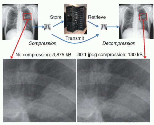
▪ FIGURE 5-8 Image compression reduces the number of bytes in an image to reduce image storage space and image transmission times. At a display workstation, an image retrieved from the archive over the network requires image decompression, which restores the images to full physical size (number of pixels) and number of bytes. Shown above is a chest image with lossless compression (left), and 30:1 jpeg lossy compression (right). Although the minified images (above) look similar, the magnified views (below) illustrate loss of image fidelity and non-diagnostic image quality with too much lossy compression.


5.3.4 Archive and Storage

An archive is a location containing records, documents, and other objects of historical importance. In the context of a PACS, the archive is a long-term storage of medical images on disks and tapes in DICOM format. In the context of enterprise storage, the archive is generally on a Vendor-Neutral Archive (VNA) that is a repository for all kinds of data, including DICOM and non-DICOM images, non-image data (e.g., EKG traces), and other content. Archiving of data and images is typically performed in a compressed format for efficient use of storage and network resources. Many lossless image compression implementations are vendor proprietary, making the archive inaccessible to non-vendor access except through a translator program that outputs standard DICOM formats. Archived data is protected from disk failures through the use of RAID (Redundant Array of Independent Disks) and from natural disasters or other catastrophes by creating a backup mirror copy in a separate location to ensure business continuity and access to data. The storage size required for a PACS or enterprise archive depends on patient workload, types of modalities, and the length of time images are to be stored and can range from terabytes (212) to petabytes (215) to exabytes (218) and beyond. The amounts of storage required for individual images and typical studies from the various imaging modalities are listed in Table 5-2. Certainly, the size and complexity of the archive are dependent on the infrastructure and characteristics of the healthcare enterprise it supports.

The PACS archive may be centralized, or it may be distributed, that is, stored at several locations on a network. In either case, there must be archive management software on a server. The archive management software includes a database program that contains information about the stored studies and their locations in the archive and indexes these based on the most common metadata for rapid retrieval. The archive management software communicates over the network with imaging devices sending
studies in for storage and sends copies of the studies received from imaging devices to the storage devices, including backup storage. The transfers between imaging devices and the PACS must conform to the DICOM standard. The archive management software must also obtain studies from the storage devices and send either the studies or selected images from them to workstations requesting studies or images for display. In PACS with hierarchical storage, the archive management software transfers studies between the various levels of archival storage, based upon factors such as the recentness of the study and, when a new study is ordered, prefetches relevant older studies from near-line storage to online storage to reduce the time required for display.

In some PACS, studies or images from studies awaiting interpretation and relevant older studies are requested by viewing workstations from the PACS archive as needed (“on-demand”) during viewing sessions, but this can slow the workflow process of the interpreting physician. Alternatively, studies may be obtained (“prefetched”) from the archive and stored on a display workstation or local file server, prior to the interpretation session, ready for the interpreting physician’s use. The prefetch method requires the interpretation workstations or server to have more local storage capacity, whereas the on-demand method requires a faster archive and faster network connections between the archive and the interpretation workstations. An advantage to the on-demand method is that a physician may use any available workstation to view a particular study, whereas to view a particular study with the prefetch method, the physician must go to a workstation that has access to the locally stored study. When images are fetched on-demand, the first image should be available for viewing within about two seconds. Once images reside on the workstation’s disk or local server, they are nearly instantaneously available.

On-demand systems may send all the images in entire studies to the workstation, or they may just send individual images when requested by the viewing workstation. The method of sending entire studies at once requires greater network bandwidth and more storage capacity on the viewing workstation and causes greater delay before the first images are displayed. On the other hand, providing only individual images upon request by the viewing workstation reduces the delay before the first image or images are displayed, but places more demand on the archive server to respond to frequent requests for individual images.

Server-side rendering in a cloud-based computing model is a growing option with current PACS, whereby thin client viewers (often zero-footprint, generally implemented in HTML-5) access an on-line server or server farm and archive. All of the processing and display is performed at the server location and only the results are pushed to the thin client. This type of arrangement generally reduces the overall network bandwidth of a hospital network because the images need only be sent to the PACS archive once, and the users can access the content with a thin client and have the server provide the image-only display results, in lieu of sending the full complement of image data to each thick-client workstation. The benefits of such centralization are hardware resource optimization, reduced software maintenance, no requirement for client management on the desktop, fast image viewing since only compressed images and not the full dataset are sent over the network, ability to scale to enterprise imaging (all of the image-based “-ologies”), and improved security, as hardware and software assets are easily firewalled, maintained, and protected. Appropriate sizing of servers, having enough concurrent software licenses, and server redundancy must be ensured to provide reliable host availability.

Two common storage schemes include hierarchical and on-line. In hierarchical storage, recent images are stored on arrays of high-performance magnetic hard disk drives or solid-state drives, and older images are stored on slower but more capacious archival storage media, such as lower-performance drives or automated magnetic tape
libraries. On-line storage describes the fraction of studies with immediate and rapid access for viewing. Near-line storage refers to storage at remote disk farms or automated libraries of magnetic tape, from which studies may be retrieved albeit less rapidly. Off-line storage refers to storage not directly accessible (requiring some human intervention to be made available). With the lowered cost of storage media, off-line mechanisms are generally no longer used as primary storage tiers, but often still employed as disaster recovery mechanisms. With magnetic tape capacities already at 30 terabytes (TB) (LTO-8 compressed, at around a $100 per cartridge) and planned to exceed 100 TB (LTO-10 compressed), many sites utilize off-site magnetic tape storage for cost-effective disaster recovery. When hierarchical storage is used, the system must automatically copy (“prefetch”) relevant older studies from near-line to on-line storage to be available without delay for comparison when new studies are viewed. An alternative to hierarchical storage is to store all images on arrays of magnetic or solid-state disk drives. As these become full, more disk arrays are added to the system, which has become feasible because of the increasing capacities of disk drives and the decreasing cost per unit storage capacity. This method is referred to as “everything online” storage.

A VNA is typically constructed to provide access to all enterprise images and data of clinical relevance, whether the content is DICOM compliant or formatted in another way, such as optical images from a dermatology clinic that may be encoded in a JPEG format or documents in a PDF (Portable Document Format) file structure. These objects are stored in a standard format with a standard interface and cataloged on a database so that they can be accessed in a vendor-neutral manner by other systems. A VNA decouples the PACS and workstations at the archival level and provides a means to coalesce access to mini-PACS and image databases. Availability to all encounter-based image workflows (situations without an order for imaging) is also achieved, associating content with the correct patient in the medical record on an Enterprise-wide basis. This provides a unified archive and access to such data, while still allowing proprietary front-end appliances and software to send information if they are compliant with rules/profiles set up by entities such as the IHE effort.


5.3.5 DICOM, HL7, and IHE

Connecting imaging devices to a PACS with a network, by itself, does not achieve the transfer of images and related information. This would permit the transfer of files, but medical imaging equipment manufacturers and PACS vendors could (and in the past did) use proprietary formats for digital images and related information. In the past, some facilities solved this problem by purchasing all equipment from a single vendor; others had custom software developed to translate one vendor’s format into another’s format. To help overcome problems such as these, the ACR and the NEMA jointly sponsor a set of standards called Digital Imaging and Communications in Medicine (DICOM) to facilitate the transfer of medical images and related information. Other professional societies work to develop medical specialty-specific DICOM standards. Many other national and international standards organizations recognize the DICOM standards.

DICOM includes standards for the transfer, using computer networks, of images and related information from individual patient studies between devices such as imaging devices and storage devices. DICOM specifies standard formats for the images and other information being transferred, services that one device can request from another, and messages between the devices. DICOM does not specify formats for the storage of information by a device itself, although a manufacturer may choose to use DICOM formats for this purpose. DICOM also includes standards for exchanging information regarding workflow; standards for the storage of images and related information on removable storage media, such as optical disks; and standards for the
consistency and presentation of displayed images. A description and complete listing of the DICOM standard is available (DICOM, 2020).

DICOM specifies hierarchical formats for information objects, such as “patients,” “studies,” and “images” (sometimes referred to as “PSSI” Patient/Study/Series/Image or Instance). These are combined into composite Information Object Definition (IOD) entities, such as the CT (computed tomography), CR (computed radiography), DX (digital x-ray), MG (digital mammography x-ray), US (ultrasound), MR (magnetic resonance imaging), and NM (nuclear medicine) IODs. DICOM specifies standard services that may be performed on information objects, such as storage, query and retrieve, storage commitment, print management, and media storage. The concept of a Service-Object-Pair (SOP) is defined by the union of an IOD and a DICOM message service element (DIMSE), for example, an SOP might be “Store a CT study.” A Service Class is a collection of related SOPs with a specific definition of a service supported by cooperating devices to perform an action on a specific IOD class (Fig. 5-9). Two
service operations are defined: Service Class User (SCU)—invokes operations, and Service Class Provider (SCP)—performs operations. Table 5-3 lists a subset of common DICOM vocabulary terms and acronyms that are widely used by PACS administrators.


▪ FIGURE 5-9 A. DICOM information model—Service/Object relationship. The Service Class specification (top rectangle) defines the services—operations such as moving, storing, finding, or printing that can be performed on data objects that DICOM can manage. The service group is comprised of DICOM Message Service Element (DIMSE) services such as “C-move,” “C-store,” “C-find,” etc., as described in Part 4 of the DICOM standard. Data objects have Information Object Definitions (IODs) with attributes defining the object (e.g., a CT series containing images). A specific combination of a Service and an Object is termed a Service-Object-Pair (SOP), middle rectangle, which constitutes the basic unit of DICOM operability. Model shown above is adapted from the DICOM standard in Part 3.3. (DICOM PS3.3-2003, by permission). B. An example might be a SOP that combines “C-Move” service with “CT” IOD. In a Conformance Statement, this might be represented as shown, attesting that the implementation can both send and receive CT images. The “UID” is a Unique Identifier associated with this particular SOP class, describing a DICOM transfer syntax.

Only gold members can continue reading. Log In or Register to continue

Stay updated, free articles. Join our Telegram channel

May 16, 2021 | Posted by in GENERAL RADIOLOGY | Comments Off on Medical Imaging Informatics

Full access? Get Clinical Tree

Get Clinical Tree app for offline access