X-ray Production, Tubes, and Generators
X-rays are produced when highly energetic electrons interact with matter, converting some or all of their kinetic energy into electromagnetic radiation. The x-ray tube insert contains an electron source, a vacuum environment, and a target electrode; an external power source provides high voltage (potential difference) to accelerate the electrons. The x-ray tube insert is mounted within a tube housing, which includes a metal enclosure; protective radiation shielding; x-ray beam filters for shaping the x-ray spectrum; and collimators, which define the size and shape of the x-ray field. The x-ray generator supplies the tube potential to accelerate the electrons, a filament circuit to control tube current, and an exposure timer. These components work in concert to produce a beam of x-ray photons with controlled fluence (number of incident photons per unit area), energy fluence (energy weighted number of photons per unit area), and a well-collimated trajectory. In terms of nomenclature used in this chapter, the fluence and energy fluence are scalar radiometric quantities. The term exposure is a dosimetric quantity describing the amount of charge in coulombs (C) released in a known mass of air (unit of C/kg) and is expressed in terms of the energy fluence and energy absorption integrated over energy. The exposure rate is the increment of exposure in a time interval (unit of C/kg/s).
This chapter describes the x-ray production process, characteristics of the x-ray beam, x-ray tube design, x-ray generator components, and factors that affect exposure and exposure rate.
6.1 PRODUCTION OF X-RAYS
6.1.1 Bremsstrahlung Spectrum
X-rays are produced from the conversion of kinetic energy of electrons into electromagnetic radiation when they are decelerated by interaction within a target material. A simplified diagram of an x-ray tube (Fig. 6-1) illustrates these components. An electrical potential difference (the SI unit of potential difference is the volt, V) of 20,000 to 150,000 V (20 to 150 kV) is applied between the electrodes. The negative pole of the voltage source is applied to the cathode, which is also the source of electrons, and the positive pole is applied to the anode, the target of electrons. Electrons are emitted by the cathode, are accelerated by the tube potential through the vacuum to strike the anode. The eV is the energy obtained by an electron after it is accelerated across a potential difference of 1 V. One eV is equal to 1.603 × 10⁻¹⁹ joule (J). An applied x-ray tube potential of 50 kV accelerates electrons to a kinetic energy of 50 keV.
On impact with the target, the kinetic energy of the electrons is converted to other forms of energy. Most interactions, typically greater than 99%, are collisional with other electrons in the target material and produce nothing but heat. Electrons that reach the proximity of an atomic nucleus in the target material are decelerated by the positive charge of the nucleus. As discussed in Chapter 3, electrical (Coulombic)
forces attract and decelerate an electron that changes its direction and velocity, resulting in the radiative emission of an x-ray photon (i.e., bremsstrahlung radiation).
forces attract and decelerate an electron that changes its direction and velocity, resulting in the radiative emission of an x-ray photon (i.e., bremsstrahlung radiation).
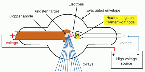 ▪ FIGURE 6-1 Minimum requirements for x-ray production include a source and target of electrons, an evacuated envelope, and connection of the electrodes to a high-voltage source. |
The magnitude of energy lost by an electron is determined by the closest distance between the incident electron and the nucleus, as the Coulombic force is proportional to the inverse square of the distance. At a relatively large distance, Coulombic attraction is weak, resulting in encounters that produce low x-ray energies (Fig. 6-2, electron no. 3). At closer interaction distance, the increased Coulombic force causes a greater electron deceleration and conversion to higher x-ray energies (see Fig. 6-2,
electron no. 2). A direct impact with the target nucleus stops an electron and converts all its kinetic energy into an equivalent energy x-ray photon (see Fig. 6-2, electron no. 1), resulting in the highest bremsstrahlung x-ray energy.
electron no. 2). A direct impact with the target nucleus stops an electron and converts all its kinetic energy into an equivalent energy x-ray photon (see Fig. 6-2, electron no. 1), resulting in the highest bremsstrahlung x-ray energy.
 ▪ FIGURE 6-2 Bremsstrahlung radiation arises from energetic electron interactions with an atomic nucleus of the target material. In a “close” approach, the positive nucleus attracts the negative electron, causing deceleration and redirection, resulting in a loss of kinetic energy that is converted to an x-ray. The x-ray energy depends on the interaction distance between the electron and the nucleus, and increases as the distance decreases. When the distance is zero (incident electron 1 in the figure), all the kinetic energy of the electron creates the maximum bremsstrahlung photon energy. |
The probability of electron interactions that produce x-rays of energy E depends on the radial interaction distance, r, from the nucleus, which defines an annulus of inner diameter 2r, and outer diameter 2(r + dr), where dr is a small fixed radial increment. Increasing the radius in steps of dr from the nucleus defines an incrementally increasing annulus area; thus electron-nucleus interactions generate incrementally larger numbers of x-rays at incrementally decreasing energies. For the closest electron-nucleus interactions (i.e., r = 0), the highest x-ray energy is produced at extremely low probability and small number of x-rays. A bremsstrahlung spectrum is the probability distribution of x-ray photon fluence produced as a function of energy, expressed in keV. The unfiltered bremsstrahlung spectrum (Fig. 6-3a) shows an inverse linear relationship between the fluence and energy of the x-rays produced, with the highest x-ray energy, x keV, determined by the peak voltage (x kV) applied across the x-ray tube. A typical filtered bremsstrahlung spectrum (Fig. 6-3b) has no x-rays present below about 10 keV; the fluence increases to a maximum at about one third to one half the maximal x-ray energy and then drops off to zero at just beyond the peak x-ray energy. Filtration in this context refers to the removal of x-rays by attenuation in materials that are inherent in the x-ray tube (e.g., the glass or metal window of the tube insert), as well as by materials that are intentionally placed in the beam, such as thin aluminum and copper sheets to preferentially attenuate lower energy x-rays and to therefore tune the x-ray spectrum for low-dose imaging (see Beam Filtration in Section 6.5).
Main factors that affect x-ray production efficiency include the kinetic energy of the incident electrons, which is directly related to the tube potential, and the atomic number (Z) of the target material. The approximate ratio of radiative energy loss (bremsstrahlung production) to collisional energy loss (excitation and ionization) within the diagnostic x-ray energy range (over a potential difference of 20 to 150 kV) is expressed as follows:

where EK is the kinetic energy of the incident electrons in keV, and Z is the atomic number of the target electrode material (anode). The most common anode is made
of tungsten (W, Z = 74); in mammography, molybdenum (Mo, Z = 42) and rhodium (Rh, Z = 45) are also used. As an example, for 100-keV electrons impinging on a tungsten target, the ratio of radiative to collisional losses is (100 × 74)/820,000 ≅ 0.009 ≅ 0.9%; at this tube potential of 100 kV, more than 99% of the incident electron energy striking the anode is converted to heat. Due to the low efficiency of x-ray production, x-ray tube design is largely driven by heat dissipation concerns.
of tungsten (W, Z = 74); in mammography, molybdenum (Mo, Z = 42) and rhodium (Rh, Z = 45) are also used. As an example, for 100-keV electrons impinging on a tungsten target, the ratio of radiative to collisional losses is (100 × 74)/820,000 ≅ 0.009 ≅ 0.9%; at this tube potential of 100 kV, more than 99% of the incident electron energy striking the anode is converted to heat. Due to the low efficiency of x-ray production, x-ray tube design is largely driven by heat dissipation concerns.
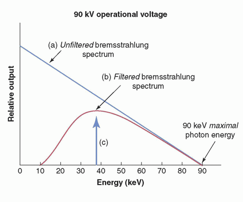 ▪ FIGURE 6-3 The bremsstrahlung energy distribution for a 90-kV acceleration potential difference. The unfiltered bremsstrahlung spectrum (a) illustrates the greater probability of low-energy x-ray photon production that is inversely linear with energy up to the maximum energy of 90 keV. The filtered spectrum (b) shows the preferential attenuation of the lowest-energy x-ray photons. The vertical arrow (c) indicates the average energy of the spectrum, which is typically 1/3 to 1/2 the maximal energy, dependent on the amount of added filtration. |
TABLE 6-1 ELECTRON BINDING ENERGIES (keV) OF COMMON X-RAY TUBE TARGET MATERIALS | ||||||||||||||||
|---|---|---|---|---|---|---|---|---|---|---|---|---|---|---|---|---|
|
6.1.2 Characteristic X-rays
In addition to the continuous bremsstrahlung x-ray spectrum, discrete x-ray energy peaks called “characteristic radiation” are present, with x-ray energies depending on the elemental composition of the anode and the applied x-ray tube voltage. Electrons in an atom are distributed in orbital “shells” and have specific electron binding energies to maintain equilibrium. The innermost shell is designated the K shell and has the highest electron binding energy, followed by the L, M, and N shells, with progressively less binding energy. Table 6-1 lists the common anode target materials and the binding energies of the K, L, and M electron shells that are “characteristic” of the element. When the kinetic energy of an incident electron exceeds the binding energy of an electron shell in a target atom, an interaction can eject an electron from its shell, creating a vacancy. As discussed in Chapter 2, an outer shell electron with less binding energy immediately transitions to fill the vacancy, and a characteristic x-ray is emitted with an energy equal to the difference in the electron binding energies of the two shells (Fig. 6-4).
 ▪ FIGURE 6-4 Generation of a characteristic x-ray in a target atom occurs in the following sequence: (1) The incident electron interacts with the K-shell electron via a repulsive electrical force. (2) The K-shell electron is removed (only if the energy of the incident electron is greater than the K-shell binding energy), leaving a vacancy in the K-shell. (3) An electron from the adjacent L-shell fills the vacancy. (4) A Kα characteristic x-ray photon is emitted with energy equal to the difference between the binding energies of the two shells. In this case, a 59.3-keV photon is emitted. |
TABLE 6-2 K-SHELL CHARACTERISTIC X-RAY ENERGIES (keV) OF COMMON X-RAY TUBE TARGET MATERIALS | ||||||||||||||||||||
|---|---|---|---|---|---|---|---|---|---|---|---|---|---|---|---|---|---|---|---|---|
| ||||||||||||||||||||
For tungsten, L-shell electrons have binding energies of 10.2, 11.5, and 12.1 keV. Electrons that transition from the L to an empty K-shell orbital produce discrete characteristic x-rays equal to the difference of 69.5 K-shell binding energy and the respective L-shell binding energies: 59.3, 58, and 57.4 keV. Orbital electrons from outer shells (M, N, …) with lower binding energy will produce characteristic x-rays of higher energy. For example, a M-shell electron of binding energy of 2.3 keV that fills the K shell vacancy produces a characteristic x-ray of 67.2 keV. Characteristic x-rays are designated by the shell in which the electron vacancy is filled, and a subscript of α or β indicates whether the electron transition is from an adjacent shell (α) or non-adjacent shell (β). For example, Kα refers to an electron transition from the L to the K shell, and Kβ refers to an electron transition from the M, N, or O shell to the K shell. It follows that a Kβ x-ray is more energetic than a Kα x-ray. Characteristic x-rays other than those generated by K-shell transitions (e.g., M → L) are too low in energy for any human imaging. Table 6-2 lists electron shell binding energies and corresponding K-shell characteristic x-ray energies of W, Mo, and Rh anode targets.
Characteristic K x-rays are produced only when the electrons impinging on the target exceed the binding energy of a K-shell electron (KBE). X-ray tube potentials must therefore be greater than 69.5 kV for W (KBE = 69.5 keV), 20.0 kV for Mo (KBE = 20.0 keV), and 23.2 kV for Rh (KBE = 23.2 keV) for characteristic x-rays to be produced on these targets. As the x-ray tube voltage increases, the ratio of characteristic to bremsstrahlung x-ray energy fluence also increases. For example, at 80 kV, approximately 5% of the total x-ray energy fluence for a tungsten anode is composed of characteristic radiation, increasing to about 10% at 100 kV. Figure 6-5 illustrates a bremsstrahlung plus characteristic radiation spectrum.
 ▪ FIGURE 6-5 The filtered spectrum of bremsstrahlung and characteristic radiation from a tungsten target with a potential difference of 90 kV illustrates specific characteristic radiation energies from Kα and Kβ transitions. Filtration (the preferential removal of low-energy photons as they traverse matter) is discussed in Section 6.5. |
6.2 X-RAY TUBES
The x-ray tube provides an environment to produce bremsstrahlung and characteristic x-rays. Major tube components include the cathode, anode, rotor/stator, glass or metal envelope, tube port, cable sockets, and tube housing, illustrated in Figure 6-6. An actual x-ray tube showing the x-ray tube insert and a cut-away of the housing is shown in Figure 6-7. The x-ray generator (Section 6.3) supplies the power and permits selection of x-ray tube voltage, tube current, and exposure time. The x-ray tube voltage is set to values from 40 to 150 kV for diagnostic imaging, and 25 to 49 kV for mammography, depending on the type of imaging exam and anatomy being imaged. The x-ray tube current, measured in milliamperes (mA), represents the number of electrons per second flowing from the cathode to the anode, where 1 mA = 6.24 × 10¹⁵ electrons/s. For projection radiography, the tube current typically ranges from 100 to 1,000 mA with exposure times less than 100 ms for most examinations. The kV, mA, and exposure time are the three major selectable parameters on the x-ray generator control panel that determine the x-ray beam characteristics. Often, the product of the tube current and exposure time is considered as one entity, the mAs (milliampere-second). These parameters are discussed further in the following sections.
6.2.1 Cathode
The cathode is the negative electrode in the x-ray tube and is comprised of an electron emitter and focusing cup (Fig. 6-8). The emitter is usually a tungsten wire tightly coiled in a filament configuration (often called the filament) electrically connected to the filament circuit in the x-ray generator. Some advanced x-ray tubes have flat surface tungsten emitters (see below). Most x-ray tubes for diagnostic imaging have two filaments of different lengths, each positioned in a slot machined into the focusing cup. Specialized tubes have 2 or 3 filaments of different length for angiography applications, and dental tubes have a single filament. Usually only one filament is energized for an imaging examination, although there are some x-ray tube/generator systems that produce a combined electron distribution by energizing both filaments simultaneously. On many x-ray systems, the small or the large filament can be manually selected, or automatically selected by the x-ray generator, depending on the technique factors (kV and mAs).
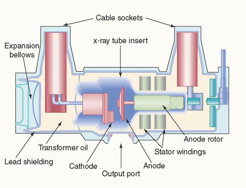 ▪ FIGURE 6-6 A diagram of the major components of a modern x-ray tube and housing assembly is shown. |
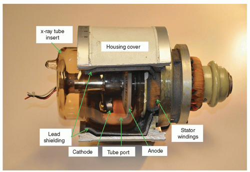 ▪ FIGURE 6-7 The x-ray tube with various components including the x-ray tube insert and partially cut-away housing. This housing has a lead shielding thickness of 2 mm. The tube port is facing downward (the lucent area between the cathode and anode in the picture). |
When energized, the filament circuit is activated to pass current with a potential difference of about 10 V through the filament. Electrical resistance heats the filament to a temperature determined by the amplitude of the current (3 to 7 amperes [A]), resulting in a release of electrons from the filament surface by a process called thermionic emission. A static electron cloud “space charge” is formed around the
filament as the repulsive force of the negative charge of emitted electrons equals the thermionic emission force. When x-ray tube voltage is applied, electrons from the filament are accelerated toward the anode, and represent the x-ray tube current. Note that the x-ray tube current and filament current are not the same but are nonlinearly related, as shown in Figure 6-9. For most diagnostic acquisitions, the x-ray fluence is emission-limited, and thus the filament circuit controls the x-ray tube current, which in turn controls the x-ray output. In situations where an already high filament current is needed to produce a higher tube current, the space charge cloud surrounding the filament emitter limits the further emission of electrons from the filament surface. In this case, the tube current cannot be increased by increases in the filament current, particularly at lower kV settings, and x-ray output is space charge limited. Higher tube potentials enable larger x-ray tube current for the same filament current; for instance, for the same filament current of 5 A at 80 kV, a tube current of 800 mA is produced, whereas at 120 kV a tube current of about 1,100 mA results.
filament as the repulsive force of the negative charge of emitted electrons equals the thermionic emission force. When x-ray tube voltage is applied, electrons from the filament are accelerated toward the anode, and represent the x-ray tube current. Note that the x-ray tube current and filament current are not the same but are nonlinearly related, as shown in Figure 6-9. For most diagnostic acquisitions, the x-ray fluence is emission-limited, and thus the filament circuit controls the x-ray tube current, which in turn controls the x-ray output. In situations where an already high filament current is needed to produce a higher tube current, the space charge cloud surrounding the filament emitter limits the further emission of electrons from the filament surface. In this case, the tube current cannot be increased by increases in the filament current, particularly at lower kV settings, and x-ray output is space charge limited. Higher tube potentials enable larger x-ray tube current for the same filament current; for instance, for the same filament current of 5 A at 80 kV, a tube current of 800 mA is produced, whereas at 120 kV a tube current of about 1,100 mA results.
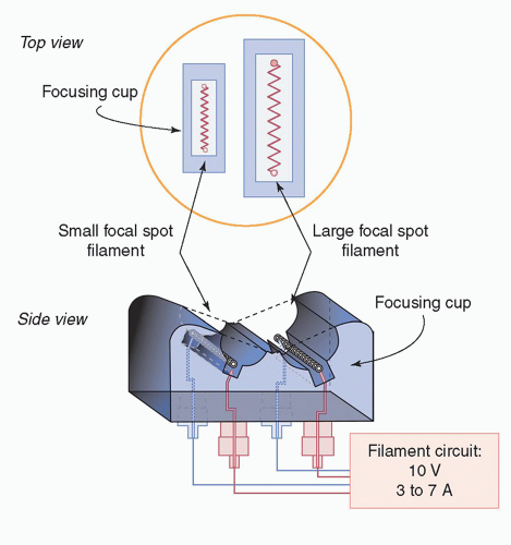 ▪ FIGURE 6-8 The x-ray tube cathode structure consists of wound tungsten filament emitters positioned within the focusing cup. The filament circuit is activated to heat the selected filament, which emits electrons by thermionic emission at the filament surface. |
 ▪ FIGURE 6-9 Relationship of tube current (number of electrons crossing the cathode-anode axis) to filament current for various applied tube kV shows a dependence of approximately kV1.5. For high filament current settings, a space charge cloud shields the electric field so that further increases in filament current do not increase the tube current. This is known as “space charge-limited” operation that occurs over a range of kV values, but in particular for lower kVs. For moderate and low filament current, the tube current is in “emission-limited” operation. |
The focusing cup surrounds the filament emitter with a slotted half-cylindrical structure. Its function is to reduce the spread of electrons during exposure. In most x-ray tubes, the focusing cup is maintained at the same potential difference as the filament relative to the anode, and an electric field exists that repels and shapes the cloud of emitted electrons from the filament surface into a tight distribution. As the tube potential is applied, electrons are accelerated to the anode, striking a small area called the focal spot (Fig. 6-10). Focal spot dimensions are determined by the length of the filament in one direction and the width of the focusing cup in the perpendicular direction.
A biased x-ray tube has a focusing cup isolated from the filament and maintained at a more negative voltage (for instance, a bias of -1,000 V), causing the electrons emerging from the filament to be even more tightly distributed by the negative repelling force and to produce a smaller focal spot width (Fig. 6-10, middle). Even greater negative voltage bias of -2,500 to -4,000 V completely stops the flow of electrons, providing a means to rapidly switch the x-ray beam on and off under high x-ray tube voltage (Fig. 6-10, right). A tube with this capability is referred to as a grid-biased x-ray tube. Grid-biased x-ray tube switching is used by advanced fluoroscopy systems
for pulsed fluoroscopy and in angiography systems to rapidly and precisely turn on and turn off the x-ray beam. Conventional x-ray generator voltage switching endures a build-up lag to get to peak voltage and a decay lag to return to 0 voltage, chiefly due to capacitance effects in the high-voltage cables. The pulse width is lengthened, and the x-ray beam energy is lowered, which results in extra patient dose and degradation of fast-moving objects in the images.
for pulsed fluoroscopy and in angiography systems to rapidly and precisely turn on and turn off the x-ray beam. Conventional x-ray generator voltage switching endures a build-up lag to get to peak voltage and a decay lag to return to 0 voltage, chiefly due to capacitance effects in the high-voltage cables. The pulse width is lengthened, and the x-ray beam energy is lowered, which results in extra patient dose and degradation of fast-moving objects in the images.
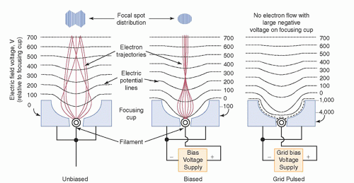 ▪ FIGURE 6-10 The focusing cup shapes the electron distribution when it is at the same voltage (“unbiased”) as the filament (left). Electrical isolation of the focusing cup from the filament and application of a negative “biased” voltage (˜ -100 V) reduces the distribution of emerging electrons by increasing the repelling electric fields surrounding the filament (note the 0 V electric field potential line) and modifying the electron trajectories (middle). At the top are typical electron distributions incident on the target anode (the focal spot) for the unbiased and biased focusing cups. Application of -4,000 V on an electrically isolated focusing cup completely stops electron flow, even with high voltage applied on the tube; this is known as a grid biased or “grid pulsed” tube (right). |
In computed tomography (CT), x-ray tubes mounted on gantries rotate as fast as 4 revolutions per second and generate high centrifugal forces, which are incompatible with conventional cathode filament emitters. Robust structural integrity is achieved with a flat surface tungsten emitter as shown in Figure 6-11. The tungsten is directly heated to release electrons via thermionic emission at temperatures much lower than a filament emitter, creating an electron distribution that is accelerated toward the anode. This technology combines mechanical and physical robustness and reduces
space charge limitations of conventional cathode emitters, but also requires focusing coils to maintain a tight distribution of electrons when impacting the anode (see Fig. 6-25).
space charge limitations of conventional cathode emitters, but also requires focusing coils to maintain a tight distribution of electrons when impacting the anode (see Fig. 6-25).
 ▪ FIGURE 6-11 A flat emitting surface cathode made of tungsten (3 mm × 10 mm active area) is used in many computed tomography x-ray tubes. It can handle the large centrifugal forces occurring at fast rotation speeds of modern CT systems and provide an efficient work function and large surface area for realizing the high tube current requirements of CT and interventional angiography. Magnetic and electrostatic coils are used to focus the electrons along the drift path to the anode, providing the flexibility to position the focal spot distribution on the anode and adjust focal spot size. (Also see Fig. 6-25.) |
6.2.2 Anode
The anode is a metal target electrode that is maintained at a positive potential difference relative to the cathode. With the cathode filament heated and voltage applied between the electrodes, electrons emitted by the cathode are accelerated toward the anode and deposit most of their energy as heat, with only a small fraction emitted as x-rays. Consequently, the rate of x-ray production, proportional to the tube current, is limited to avoid heat damage to the anode. The anode area impacted by the electrons, the focal spot, also limits the amount of power density (energy per unit time per unit area) that can be deposited. Tungsten is the most widely used anode material because of its high melting point (3,000°C) and high atomic number (Z = 74). A tungsten anode can handle substantial heat deposition without cracking or pitting of its surface. An alloy of 10% rhenium and 90% tungsten provides added resistance to surface heat damage. In addition, tungsten provides greater bremsstrahlung production for the same tube current than lower Z elements (Eq. 6-1).
6.2.3 Anode Configurations: Stationary and Rotating
A simple x-ray tube design has a stationary anode, consisting of a tungsten insert embedded in a copper block (Fig. 6-12). Copper serves a dual role: it mechanically supports the W insert and efficiently conducts heat from the tungsten target. However, the small area of the focal spot limits the tube current that can be sustained without damage from excessive temperature. Dental x-ray units, low-output mobile x-ray machines, and mobile fluoroscopy systems use fixed-anode x-ray tubes.
Rotating anodes allow higher x-ray output by spreading the heat over a larger area as the anode surface rotates relative to the electron beam. The rotating anode is designed as a beveled disk mounted on a rotor assembly supported by bearings in the x-ray tube insert for radiographic x-ray tubes (Fig. 6-13). In many x-ray tube anodes for radiography and fluoroscopy applications, the bulk of the material is molybdenum, with a tungsten target blended with 3% to 10% of rhenium to enhance ductility of ˜0.5 mm thickness sintered onto the focal track area. The rotor consists of copper bars arranged around a cylindrical iron shell. A donut-shaped stator device, comprised of electromagnet coils, surrounds the rotor and is mounted outside of the
x-ray tube insert. Before an exposure, the stator/rotor induction motor is energized to spin the anode, and after a short delay, rotation speeds of 3,000 to 3,600 (low speed) or 9,000 to 10,000 (high speed) revolutions per minute (rpm) are achieved. X-ray tube-generator systems for general radiography are designed such that the x-ray tube voltage is applied only when the anode is at full speed, causing a short delay (1 to 2 seconds [s]) prior to x-ray exposure when the button is pushed by the technologist.
x-ray tube insert. Before an exposure, the stator/rotor induction motor is energized to spin the anode, and after a short delay, rotation speeds of 3,000 to 3,600 (low speed) or 9,000 to 10,000 (high speed) revolutions per minute (rpm) are achieved. X-ray tube-generator systems for general radiography are designed such that the x-ray tube voltage is applied only when the anode is at full speed, causing a short delay (1 to 2 seconds [s]) prior to x-ray exposure when the button is pushed by the technologist.
 ▪ FIGURE 6-12 The anode of a fixed anode x-ray tube consists of a tungsten insert mounted in a copper block. Generated heat is removed from the tungsten target by conduction into the copper block. |
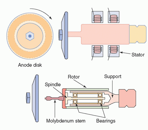 ▪ FIGURE 6-13 The anode of a rotating anode x-ray tube is a tungsten disk mounted on a bearing-supported rotor assembly (front view, top left; side view, top right). The rotor consists of a copper and iron laminated core and forms part of an induction motor. The other component is the stator, which exists outside of the insert, top right. A molybdenum shaft (molybdenum is a poor heat conductor) connects the rotor to the anode to reduce heat transfer to the rotor bearings (bottom). |
Rotor bearings are heat sensitive and are often the cause of x-ray tube failure. Bearings require special non-volatile lubricants in the vacuum environment of the x-ray tube insert. Thermal insulation from the hot anode is achieved by using a connector stem to the rotor made of molybdenum, a very poor heat conductor; in fact, most solid anodes are made of molybdenum as the base metal with a tungsten target insert. Most rotating anodes for radiography are cooled by radiative (infrared) emission, transferring heat to the x-ray tube insert and to the surrounding oil bath and tube housing. In imaging situations demanding anodes with higher heat loads and more rapid cooling, sophisticated engineering designs are employed. A tungsten/rhenium (90%-10%) conversion layer of 0.5 to 1 mm thickness and anode support structure made of titanium-zirconium-molybdenum powder-sintered alloy can maintain mechanical integrity at temperatures in excess of 1,200°C. Liquid metal rotor bearings can readily conduct heat for quick cooling with heat exchanger systems using oil or water coolant (see special x-ray tube designs in this section).
The focal track area of the rotating anode is approximately equal to the product of the circumferential track length (2πr) and the track width (Δr), where r is the radial distance from the axis of the anode to the center of the track (Fig. 6-14). A rotating anode with a 50-mm focal track radius and a 1-mm track width provides a focal track with an annular area 314 times greater than that of a fixed anode with a focal spot area of 1 × 1 mm. The allowable instantaneous power loading depends on the anode rotation speed and the focal spot area. Faster rotation distributes the heat load over a greater fraction of the focal track area for short exposure times. A larger focal spot distributes energy over a larger anode area and allows much higher output rate to keep exposures short, and should be used in situations where patient motion can be a problem and geometric magnification is small (refer to Chapter 7). Conversely, a small focal spot should be used when magnification is employed, and the likelihood of patient motion is low, because of extended exposure times.
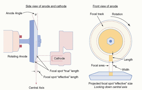 ▪ FIGURE 6-14 The anode (target) angle, θ, is defined as the angle of the anode surface in relation to the central axis (left). The focal track represents the total area over which heat is distributed during the x-ray exposure as the anode rotates. The actual focal area is characterized by a length and width (right). The focal spot length, as projected down the central axis, is foreshortened, according to the line focus principle (lower right). |
6.2.4 Anode Angle, Field Coverage, and Focal Spot Size
The actual focal spot size is the physical area on the anode that is struck by electrons and is primarily determined by the length of the cathode filament and the width of the focusing cup slot. However, the projected length of the focal spot area at the central ray in the x-ray field is much smaller, because of geometric foreshortening of the projected distribution from the anode surface. The effective and actual focal spot lengths are geometrically related as
where θ is the anode angle. The sin θ term has values from 0.12 for a 7° angle to 0.34 for a 20° angle. The line focus principle describes the foreshortening of the focal spot length projected down the central ray, per Equation 6-2.
EXAMPLE: The actual anode focal area for a 15° anode angle is 5 mm (length) by 1.2 mm (width). What is the projected focal spot size at the central axis position?
Answer: Effective length = actual length × sin θ = 5 mm × sin (15°) = 5 mm × 0.26 = 1.29 mm; therefore, the projected focal spot area is 1.29 mm (length) by 1.2 mm (width).
What are the considerations for choosing an anode angle? For x-ray tube designs with a small anode angle, the effective focal spot size is smaller for the same actual focal area; alternatively, the effective focal spot size remains the same with a longer filament and a larger actual focal area. The first design is beneficial when magnification
is employed to reduce geometric blurring; the second design is beneficial when high exposure rate is needed for shortest exposure times using higher mA. However, a small anode angle limits the usable x-ray beam coverage at a given focal spot-to-detector distance, because of beam cutoff on the anode side of the projected x-ray field. In addition, field coverage is smaller for shorter focal spot-to-detector distances (Fig. 6-15). Therefore, the optimal x-ray tube anode angle depends on the clinical imaging application. A small anode angle (˜7° to 9°) is desirable for limited field-of-view devices, such as CT scanners with narrow collimation in the A-C dimension, and fluoroscopy C-arm devices where field coverage is determined by the small image receptor diameter (e.g., 23 cm) and focal spot-to-detector distance of 100 cm. Larger anode angles (˜12° to 15°) are necessary for general radiographic imaging to achieve large field area coverage (e.g., 43 cm length of a digital detector) at typical focal spot-to-detector distances of 100 cm.
is employed to reduce geometric blurring; the second design is beneficial when high exposure rate is needed for shortest exposure times using higher mA. However, a small anode angle limits the usable x-ray beam coverage at a given focal spot-to-detector distance, because of beam cutoff on the anode side of the projected x-ray field. In addition, field coverage is smaller for shorter focal spot-to-detector distances (Fig. 6-15). Therefore, the optimal x-ray tube anode angle depends on the clinical imaging application. A small anode angle (˜7° to 9°) is desirable for limited field-of-view devices, such as CT scanners with narrow collimation in the A-C dimension, and fluoroscopy C-arm devices where field coverage is determined by the small image receptor diameter (e.g., 23 cm) and focal spot-to-detector distance of 100 cm. Larger anode angles (˜12° to 15°) are necessary for general radiographic imaging to achieve large field area coverage (e.g., 43 cm length of a digital detector) at typical focal spot-to-detector distances of 100 cm.
The nominal focal spot size (length and width) is specified at the central ray of the beam. The focal spot length dimension projected toward the anode side of the field becomes smaller, whereas it becomes larger toward the cathode side (Fig. 6-16). The width of the focal spot does not change appreciably with position in the image plane.
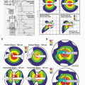
Estimating focal spot dimensions can be performed in several ways. Common tools for measuring focal spot size include the pinhole camera, slit camera, star pattern, and resolution bar pattern (Fig. 6-17). In 2005, the International Electrotechnical Commission (IEC) released the International Standard 60336 for measuring focal spots in medical x-ray tubes. Recommendations for detailed measurements and analysis using the first three tools mentioned above are included in that document. The pinhole camera uses a tiny circular aperture (10 to 30 µm diameter) in a thin, highly attenuating metal disk to project a magnified image of the focal spot onto an image receptor. Figure 6-17E shows magnified (2×) pinhole pictures of the large (top row)
and small (bottom row) focal spots with a typical “bi-gaussian” intensity distribution. Correcting for the known image magnification allows one to estimate the focal spot dimensions. The slit camera consists of a highly attenuating metal plate with an extremely thin slit, typically 10 µm wide, and is the primary method described in the IEC 60336 standard to evaluate focal spot dimensions. Slit images are shown in Figure 6-17F. The star pattern test tool (Fig. 6-17G) contains a metal (lead) attenuator radial spoke pattern of diminishing width and spacing on a thin plastic disk. Imaging the star pattern at a known magnification, and measuring the distance between the outermost blur patterns (location of the outermost unresolved spokes as shown by the arrows in Fig. 6-17G) on the image allows the calculation of the effective focal spot dimensions in the directions perpendicular and parallel to the A-C axis. A large focal spot will have a greater blur diameter than a small focal spot, as shown in the figure. For a quick and simple estimate of focal spot size, a resolution bar pattern with discrete line pairs can be employed (Fig. 6-17H). Bar pattern images demonstrate the effective resolution parallel and perpendicular to the A-C axis for a given magnification geometry, determined by the bar pattern that can be resolved. If a focal spot dimension is determined to be out of tolerance using this method, one of the methods approved by the IEC standard should be used for more precise evaluation.
and small (bottom row) focal spots with a typical “bi-gaussian” intensity distribution. Correcting for the known image magnification allows one to estimate the focal spot dimensions. The slit camera consists of a highly attenuating metal plate with an extremely thin slit, typically 10 µm wide, and is the primary method described in the IEC 60336 standard to evaluate focal spot dimensions. Slit images are shown in Figure 6-17F. The star pattern test tool (Fig. 6-17G) contains a metal (lead) attenuator radial spoke pattern of diminishing width and spacing on a thin plastic disk. Imaging the star pattern at a known magnification, and measuring the distance between the outermost blur patterns (location of the outermost unresolved spokes as shown by the arrows in Fig. 6-17G) on the image allows the calculation of the effective focal spot dimensions in the directions perpendicular and parallel to the A-C axis. A large focal spot will have a greater blur diameter than a small focal spot, as shown in the figure. For a quick and simple estimate of focal spot size, a resolution bar pattern with discrete line pairs can be employed (Fig. 6-17H). Bar pattern images demonstrate the effective resolution parallel and perpendicular to the A-C axis for a given magnification geometry, determined by the bar pattern that can be resolved. If a focal spot dimension is determined to be out of tolerance using this method, one of the methods approved by the IEC standard should be used for more precise evaluation.
Related posts:
Stay updated, free articles. Join our Telegram channel

Full access? Get Clinical Tree


