LEARNING OBJECTIVES
1. Describe and identify on chest radiography the normal appearance and complications associated with each of the following:
• Endotracheal tube
• Central venous catheter
• Peripherally inserted central venous catheter
• Pulmonary artery catheter
• Enteric drainage and feeding tubes
• Chest tube
• Intra-aortic balloon pump
• Pacemaker generator and leads
• Automatic implantable cardiac defibrillator
• Ventricular assist device
• Intraesophageal manometer, temperature probe, and pH probe
2. Explain how an intra-aortic balloon pump works.
3. Describe how a ventricular assist device works and three indications for placement.
4. Describe the venous anatomy and expected course of veins from the axillary vein to the right atrium relative to anatomic landmarks.
5. Recognize the difference between a skin fold or chest tube track and pneumothorax on a frontal chest radiograph.
One of the most useful and cost-effective functions of chest radiography is the evaluation of placement and complications related to physiologic monitoring and support devices. This is especially true for chest radiographs of patients in intensive care units, who often have several such devices in place at one time. The placement of these tubes and lines is often the first thing a radiologist interprets on a chest radiograph from a patient in an intensive care unit. Because this is such a common and impactful indication for chest radiography, frequently resulting in a change in patient management (thus often requiring a call to the ordering physician), it is important for the interpreting radiologist to understand the function, normal radiographic appearance, and complications of the more commonly placed tubes and lines. The specific appearances of these devices vary by manufacturer and local practice, so it is important to become familiar with the specific characteristics of the devices used in a particular clinical setting.
CENTRAL VENOUS CATHETERS (“LINES”)
Central venous catheters, often referred to as CVP (central venous pressure) lines, are used to monitor CVP and administer fluids intravenously. A centrally placed catheter ensures more consistent venous flow than does a route through the peripheral veins, which may vasoconstrict, particularly during periods of cardiovascular collapse. The internal jugular, subclavian, and femoral veins constitute the three most common access sites for CVP catheter placement.
The origins of the brachiocephalic veins (BCV) are demarcated by the sternoclavicular joint. Catheters within the left BCV show an anterior curve on the lateral chest radiograph because the left BCV crosses anteriorly to join the right BCV (Fig. 5.1). The subclavian veins drain the upper extremities and are a continuation of the axillary veins at a point demarcated by the lateral aspect of the first rib. The internal and external jugular and vertebral veins also contribute to the origin of each BCV. The left superior intercostal vein drains the second through fourth posterior intercostal veins and arches anteriorly to join the left BCV. It courses along the aortic arch, occasionally forming a rounded projection on the frontal chest radiograph referred to as the “aortic nipple.”
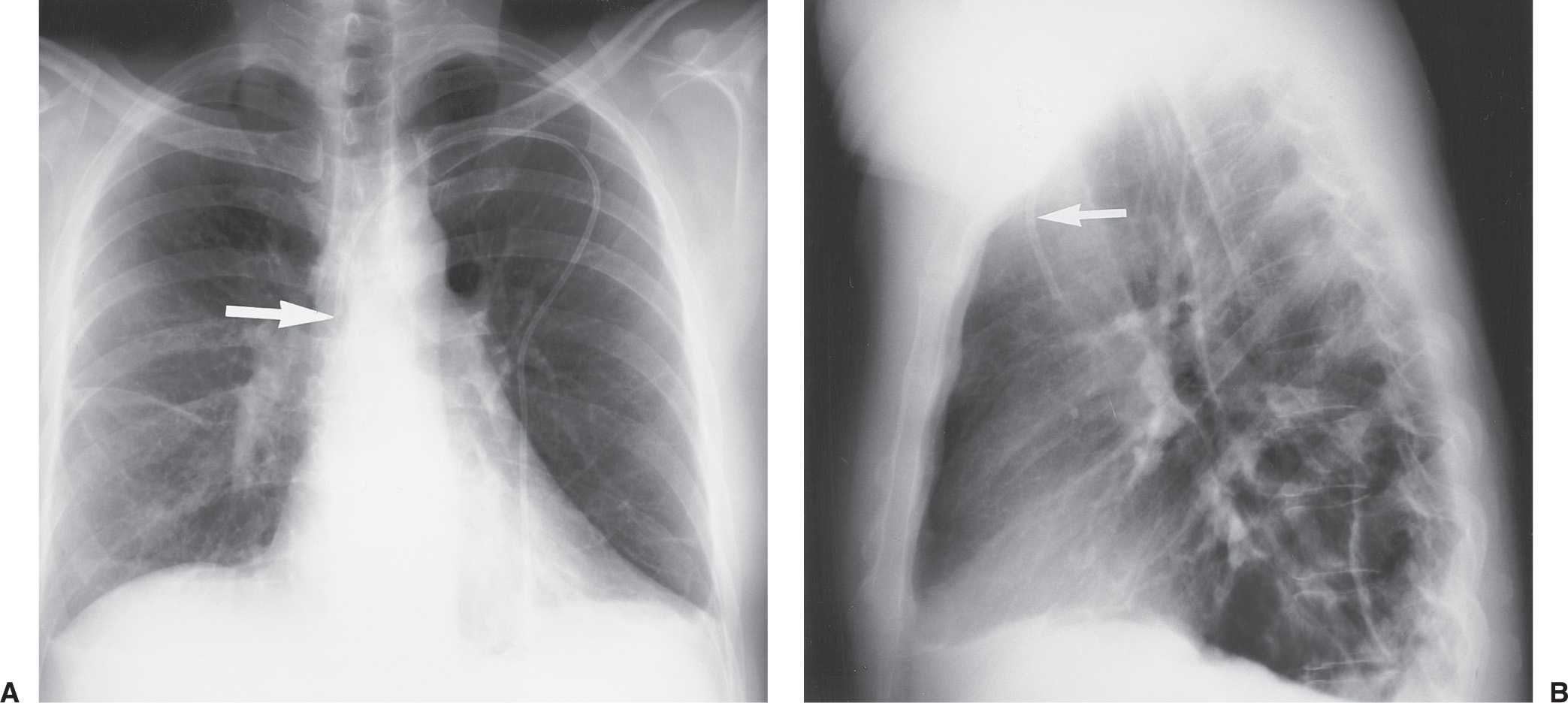
FIG. 5.1 • Left subclavian vein central venous catheter placement. A: Posteroanterior (PA) chest radiograph shows the catheter entering the left subclavian vein under the left clavicle, crossing the midline as it courses to the right, and descending, with the tip positioned over the expected superior vena cava (SVC) (arrow). B: Lateral chest radiograph shows the catheter curving anteriorly (arrow), where it crosses from the left brachiocephalic vein to join the right brachiocephalic vein. This anterior curve makes it possible to determine on a lateral radiograph that a catheter has been placed from the left side.
The preferred position of a CVP catheter tip is central to the venous valves, at the origin of the superior vena cava (SVC). The SVC is formed by the junction of the right and left BCVs. This junction lies to the right of midline at the level of the first intercostal space. The SVC is the preferred location for measuring CVP and avoiding catheter complications. The SVC is joined by the azygos vein posteriorly, just prior to entering the pericardium. Posterior orientation of the catheter tip suggests that it enters the azygos vein (Fig. 5.2).
Peripherally inserted central catheters (PICCs) are small-caliber tubes that can be left in place for long durations. The preferred position of these catheters is reported to be the distal SVC (1, 2); however, at some institutions, these catheters are placed in the radiology department, under direct fluoroscopic guidance, into the right atrium. There is little or no risk of atrial rupture or dysrhythmia with this placement, and there is a decreased incidence of peritip thrombus, which occurs with SVC placement in up to 90% of patients (3).
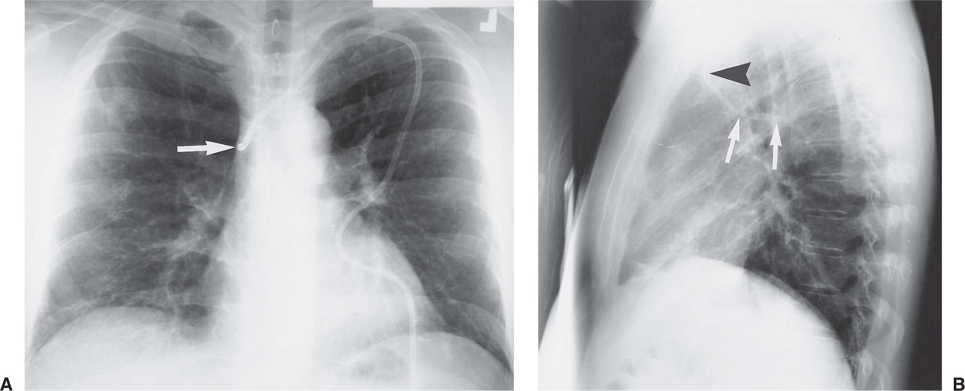
FIG. 5.2 • Azygos vein placement of central venous catheter. A: PA chest radiograph shows that the catheter tip is positioned over the expected SVC. The tip is seen on end (arrow), which is a clue to azygos vein placement. The SVC is joined by the azygos vein posteriorly. B: Lateral chest radiograph shows the catheter coursing posteriorly, along the expected course of the azygos vein (arrows). Note how the more proximal portion of the catheter curves anteriorly (arrowhead), confirming placement from the left.
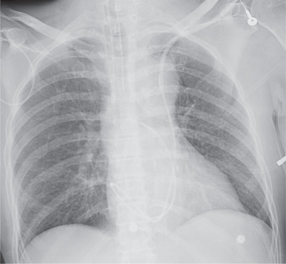
FIG. 5.3 • Left superior vena cava placement of central venous catheter. PA chest radiograph shows that instead of crossing the midline to enter the SVC on the right, the catheter courses inferiorly where projected over the aortic arch, which is typical of placement within a persistent left SVC. The catheter then follows an expected course through the coronary sinus, right atrium, right ventricle, and pulmonary outflow track.
A left-sided SVC, a normal anatomic variant, is found in 0.3% of normal individuals (Fig. 5.3). Eighty percent of such patients also have a right-sided SVC, and 60% have a left BCV connecting the right and left SVCs (4). When a left SVC is present, both the right SVC and the left BCV are usually diminutive. The left SVC most commonly drains into the right atrium via a dilated coronary sinus.
Many potential complications of CVP catheter placement can be recognized on chest radiography (Table 5.1). As many as one-third of CVP catheters are placed incorrectly at the time of initial insertion (5) (Figs. 5.4 to 5.6). The most common aberrant locations include the internal jugular vein, the right atrium or ventricle, the opposite subclavian vein, the corresponding artery, the inferior vena cava, and various extrathoracic locations detailed below. Placement within the right atrium can lead to cardiac perforation by the catheter (although this is less of a risk with some of the commonly used, peripherally placed, flexible, small-bore PICCs) (6). Positioning in the area of the tricuspid valve can cause dysrhythmias. Aberrant positioning will interfere with accurate measurement of CVP and can lead to infusion of potentially toxic substances directly into the liver or heart rather than into the central venous system, where rapid dilution can take place. Catheter tips that are directed against the lateral wall of the SVC can produce excess focal pressure on the venous wall, leading (although rarely) to venous perforation (7).
Table 5.1 COMPLICATIONS RESULTING FROM CENTRAL VENOUS CATHETER PLACEMENT
Malposition
Opposite subclavian vein
Internal jugular vein with tip directed cephalad
Corresponding artery
Right atrium
Right ventricle
Extrathoracic location
Pneumothorax—usually immediate, may be delayed
Ectopic infusion of fluid into mediastinum or pleural space
Catheter breakage and embolization
Inadvertent puncture of subclavian artery
Air embolization
“Pinch-off” syndrome between the clavicle and first rib
Venous perforation
Thrombosis
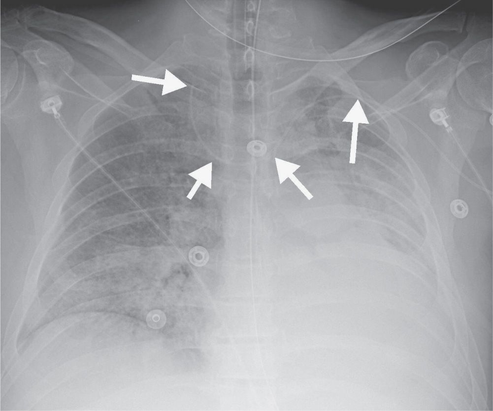
FIG. 5.4 • Malpositioned left peripherally inserted central venous catheter (PICC). AP chest radiograph shows a PICC (arrows) placed from the left side, crossing the midline, with the tip directed cephalad over the expected right jugular vein.
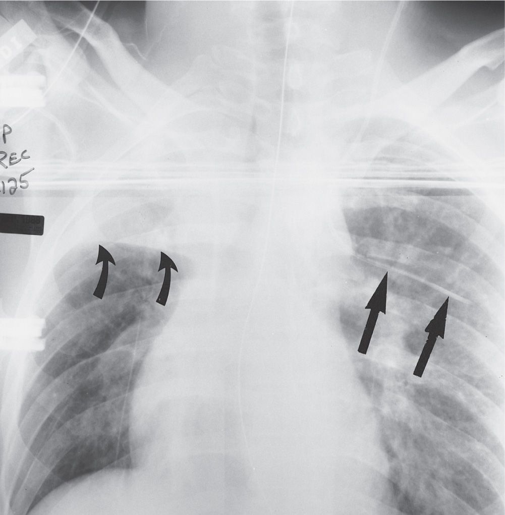
FIG. 5.5 • Intercostal vein placement of central venous catheter. Anteroposterior (AP) recumbent chest radiograph shows the left jugular central venous catheter crossing to the left and coursing horizontally, inferior to the left fifth posterior rib, typical of intercostal vein placement (straight arrows). The intercostal vessels and nerves are inferior to the rib; when performing thoracentesis, the needle should be inserted along the top of the rib to avoid puncturing these vessels. Note the collapse of the right upper lobe, with superior displacement of the minor fissure (curved arrows).
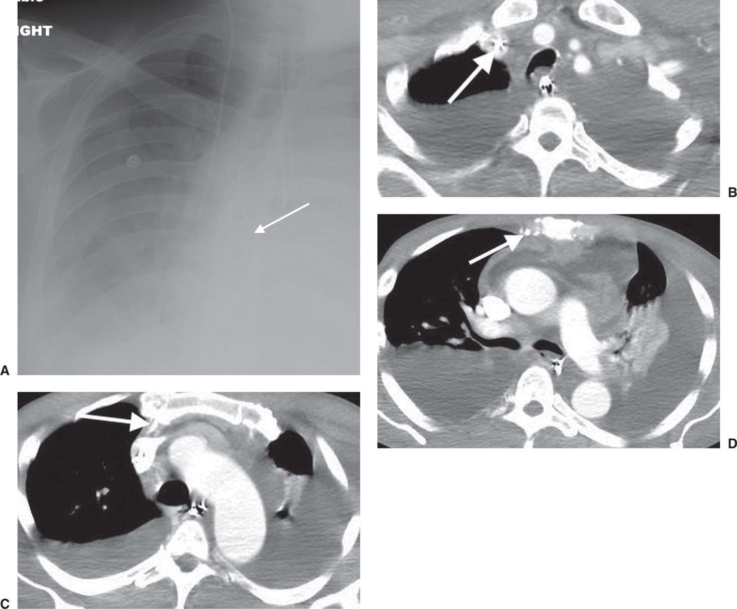
FIG. 5.6 • Malpositioned catheter tip in internal mammary vein. A: PA chest radiograph shows a right PICC, which courses more medially than expected for SVC placement (arrow). B: CT scan shows the PICC to be within the right subclavian vein (arrow). C: CT at a level inferior to (B) shows the PICC coursing anteriorly (arrow). D: CT at a level inferior to (C) shows the PICC tip to be within the right inferior mammary vein (arrow). There are also pericardial and pleural effusions.
Pneumothorax occurs with 6% of CVP catheter placements (8). In evaluating for pneumothorax, the entire pleural surface should be evaluated bilaterally, because a failed attempt at placement of a CVP catheter on one side may have gone undetected clinically before successful placement on the opposite side. Every chest radiograph should be evaluated for pneumothorax when a CVP catheter is present. This is because the initial radiograph, especially if supine, may not demonstrate the pneumothorax, and pneumothorax can persist several days after line placement (9). Skin folds, commonly seen on supine chest radiographs, may produce a thin radiopaque line that mimics a pneumothorax. Repeating the exam after repositioning the patient usually solves the dilemma.
Also occurring with CVP catheters placed via the subclavian vein is the complication of ectopic infusion of fluid into the mediastinum or pleural space (10) (Fig. 5.7). The rapid accumulation of fluid opacifying the mediastinum or pleural space after insertion of a subclavian catheter should suggest the diagnosis of ectopic infusion, which can be confirmed by injection of contrast through the catheter or thoracentesis if the fluid is accumulating in the pleural space.
Laceration of the catheter by the insertion needle, catheter fracture at a point of stress, or detachment of the catheter from its hub can result in catheter embolization. The catheter fragment can lodge in the SVC, inferior vena cava, right side of the heart, or pulmonary artery and can cause thrombosis, infection, or perforation (11).
Inadvertent puncture of the subclavian artery during subclavian vein CVP catheter placement can result in localized bleeding, which may be self-limiting but is rarely severe enough to require surgical intervention (Figs. 5.8 and (5.9). Air embolization can occur during venipuncture or intravenous contrast injection. When this occurs, air may be visible in the pulmonary artery on a chest radiograph or computed tomographic (CT) scan, signifying this usually asymptomatic but potentially fatal complication. Clot frequently forms around the catheter tip with prolonged catheter placement, resulting in malfunctioning of the catheter. If thrombus progresses, venous occlusion and even pulmonary embolus can result. “Pinch-off” syndrome refers to compression of a CVP catheter between the clavicle and the first rib. This compression can lead to catheter fracture or fragmentation (12).
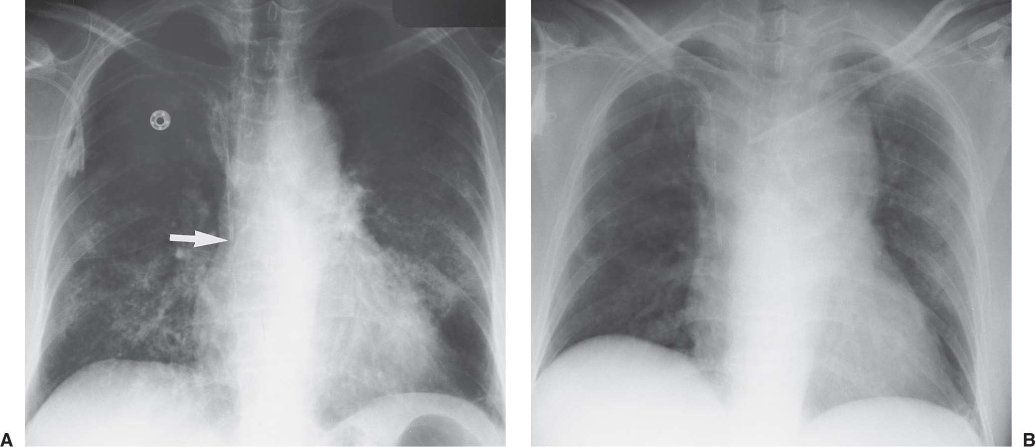
FIG. 5.7 • Malpositioned catheter resulting in ectopic fluid administration. A: PA chest radiograph obtained prior to left catheter placement. The right subclavian central venous catheter tip is positioned over the expected junction of the SVC and right atrium (arrow). B: PA chest radiograph after placement of a new left subclavian central venous catheter shows acute widening of the mediastinum from extravascular placement of the catheter and ectopic infusion of fluid into the mediastinum. The extravascular location of the catheter is not obvious on the radiograph, but the change in mediastinal width should prompt further investigation to confirm catheter position.
PULMONARY ARTERY CATHETERS
Pulmonary artery catheters consist of a central channel to monitor left atrial pressure and a second channel connected to an inflatable balloon at the catheter tip (13). A third channel measures CVP and cardiac output. The catheter is usually inserted from a subclavian vein approach, but jugular and femoral vein approaches are also used through a sheath called a cordis. The sheath allows easy advancement and withdrawal of the catheter and serves as short-term venous access after the pulmonary artery catheter has been removed. The purpose of the pulmonary artery catheter is to measure pulmonary capillary wedge pressure, which reflects left atrial pressure and left ventricular end-diastolic volume. Measurements of pulmonary capillary wedge pressure help to differentiate cardiogenic from noncardiogenic pulmonary edema. The ideal catheter tip position is within the right or left pulmonary artery or within the proximal interlobar artery. Inflation of the balloon causes the catheter to float into a peripheral pulmonary artery branch, in a wedged position, and deflation of the balloon results in the catheter resuming its more central position.
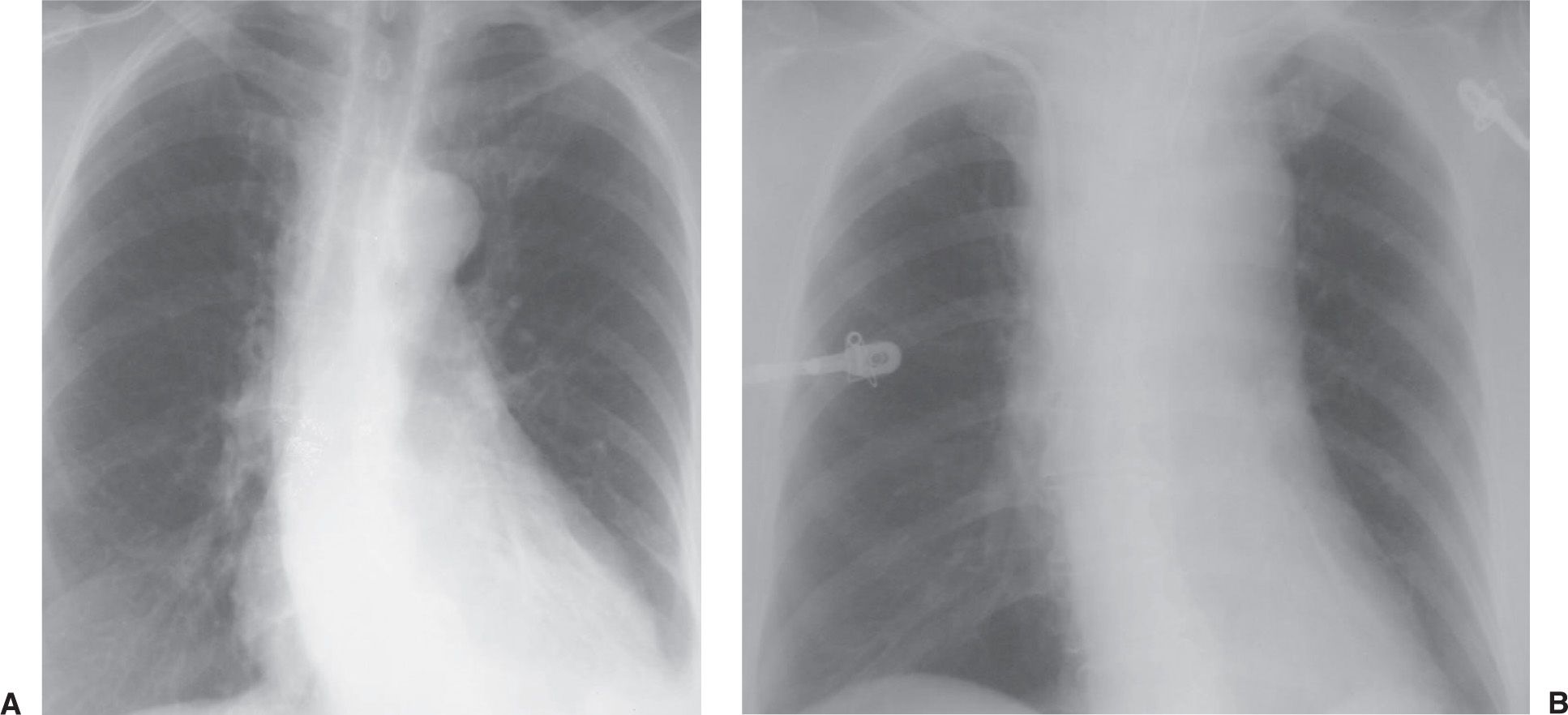
FIG. 5.8 • Mediastinal hematoma from subclavian artery perforation. A: PA chest radiograph prior to catheter placement shows a normal upper mediastinal width. B: PA chest radiograph after placement of right subclavian central venous catheter shows acute widening of the mediastinum.
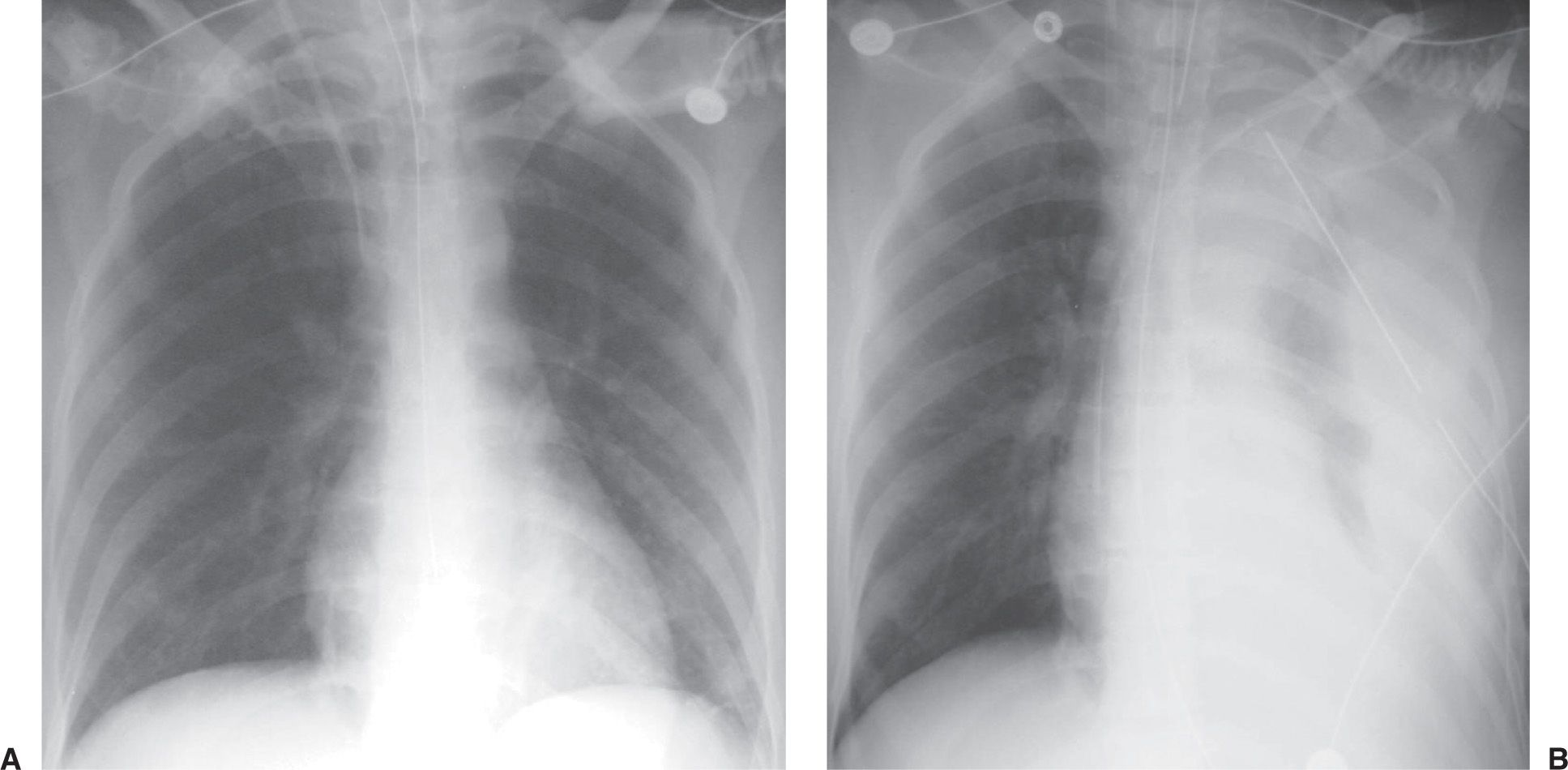
FIG. 5.9 • Hemothorax as a complication of central venous catheter placement. A: PA chest radiograph shows a normally positioned right jugular central venous catheter. B: PA chest radiograph after removal of the right catheter and placement of left subclavian central venous catheter shows a new large left pleural effusion. A chest tube was placed, which drained bright red blood.
An important complication associated with the pulmonary artery catheter is pulmonary infarction distal to the catheter tip (14). This occurs when the catheter tip is placed too distally within the pulmonary artery. As the diameter of the catheter approaches the diameter of the pulmonary artery in which the catheter resides, occlusion of the artery by the catheter occurs. Clot can also form around the tip of the catheter and occlude the pulmonary artery, occasionally leading to pulmonary infarction (seen as patchy airspace opacification, often wedge-shaped and in a subpleural location).
The pulmonary artery catheter balloon appears radiographically as a 1-cm rounded radiolucency at the tip of the catheter (Fig. 5.10). The balloon should be inflated for only a very short period of time, during measurement of pressure, and it should not be inflated while chest radiography is performed. If the balloon is left inflated, it can obstruct a major pulmonary artery and lead to pulmonary infarction.
Coiling or redundancy of pulmonary artery catheter tubing in the right side of the heart can irritate the myocardial conduction bundle and result in dysrhythmias (Fig. 5.11). Other potential complications of pulmonary artery catheter placement include pulmonary artery rupture (leading to pulmonary hemorrhage), pulmonary artery pseudoaneurysm (Figs. 5.12 and (5.13), fistulae between the pulmonary artery and the bronchial tree, intracardiac knotting of the catheter, and balloon rupture (Table 5.2). Complications that can occur with CVP catheter placement can also occur with pulmonary artery catheter placement (Fig. 5.14).
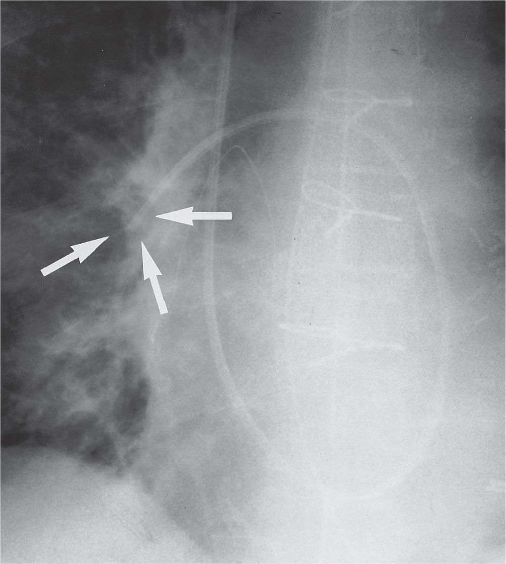
FIG. 5.10 • Inflated pulmonary artery catheter balloon. AP recumbent intraoperative chest radiograph, taken during measurement of pulmonary capillary wedge pressure, shows the inflated radiolucent balloon at the tip of the catheter (arrows). Normally, the balloon should not be inflated during the time of radiographic exposure. The balloon should be inflated for only a short period while measurements are obtained and then immediately deflated; when left inflated for longer periods, blood flow distal to the balloon is interrupted, resulting in pulmonary infarction.
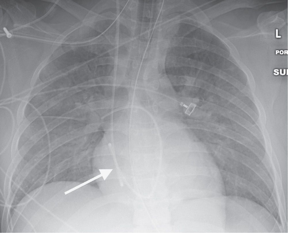
FIG. 5.11 • Looping of pulmonary artery catheter tubing. AP chest radiograph shows looping of the pulmonary artery catheter tubing (arrow) over the expected right atrium. This redundancy of catheter tubing can lead to dysrhythmias.
INTRA-AORTIC BALLOON PUMP
The intra-aortic balloon pump (IABP) (also called an intra-aortic counterpulsation balloon) is used in some centers to improve cardiac function in the setting of cardiogenic shock. The device consists of a long inflatable balloon (26 to 28 cm in length) that surrounds the distal end of a centrally placed catheter. The catheter is placed via a femoral artery retrograde to the thoracic aorta. The balloon is inflated during diastole (increasing diastolic pressure to the coronary arteries and increasing oxygen delivery to the myocardium) and is forcibly deflated during systole (decreasing left ventricular afterload and oxygen requirements). A commonly used IABP is radiolucent, except for a radiopaque marker that defines its tip. The balloon can be seen as a long tubular radiolucency (Figs. 5.15 and (5.16), following the expected course of the descending thoracic aorta to the left of the thoracic spine, if the radiograph is exposed during diastole when the balloon is inflated. The ideal location of the tip is just distal to the left subclavian artery (projecting at the level of the aortic arch on a frontal chest radiograph), allowing maximal augmentation of diastolic pressures in the proximal aorta. Even with appropriate positioning, the mesenteric and renal artery ostia are crossed by the long balloon (15). If the IABP is advanced too far, it may obstruct the left subclavian artery (Fig. 5.17) or cause cerebral embolus. If the IABP is not advanced far enough, less effective counterpulsation can result (Fig. 5.18).
Aortic dissection can occur during IABP insertion, which may result in death (16). Other potential complications include reduction of platelets, red blood cell destruction, peripheral emboli, balloon rupture with gas embolus, renal failure, and vascular insufficiency of the catheterized limb (17) (Table 5.3).
VENTRICULAR ASSIST DEVICE
Ventricular assist devices (VADs) are surgically implanted mechanical devices used in some medical centers to perform the work of the right (RVAD), left (LVAD), or bilateral (BVAD) ventricles in patients with intractable congestive heart failure. VADs can be implanted to support the failing heart and serve as a “bridge to transplant.” In some patients with reversible forms of cardiac failure, a VAD can be implanted with the hope that it will allow the heart to recover; the assist device can be removed later. This indication is known as “bridge to recovery.” In selected patients who are not good candidates for cardiac transplantation because of other medical complications, VADs can be implanted as a means of supporting circulation over a period of years. This indication is known as “destination therapy.” The new generation of pumps is designed for chronic, out-of-hospital use so that most patients can return home after the VAD is implanted. Reported complications from VAD placement, recognized on chest radiographs and CT scans, include pneumothorax, hemothorax, infection, thromboembolism, bowel obstruction, and mechanical failure (18).
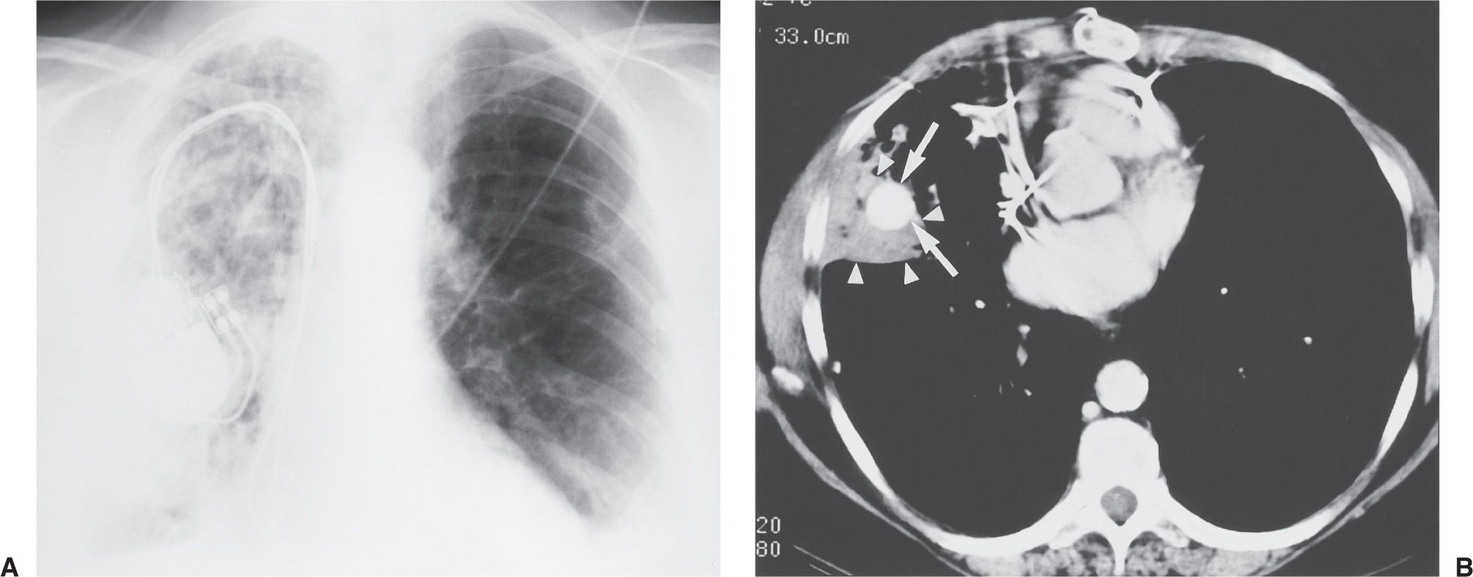
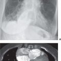
FIG. 5.12 • Pulmonary artery pseudoaneurysm as a complication of pulmonary artery catheter placement. A: AP recumbent chest radiograph in a 66-year-old woman with a history of chronic obstructive pulmonary disease and prior lung volume reduction surgery. The image was taken shortly after right heart catheterization, during which time a pulmonary artery catheter was placed into the right pulmonary artery to measure pulmonary capillary wedge pressure. The radiograph shows diffuse airspace disease in the right lung, consistent with acute pulmonary hemorrhage, which was new compared with a precatheterization radiograph. B: CT scan obtained after administration of intravenous contrast material, performed the same day as the chest radiograph in (A), shows an enhancing peripheral pulmonary artery pseudoaneurysm (arrows), with surrounding pulmonary hemorrhage (arrowheads). The pseudoaneurysm was embolized with coils by an interventional radiologist, and the bleeding stopped.
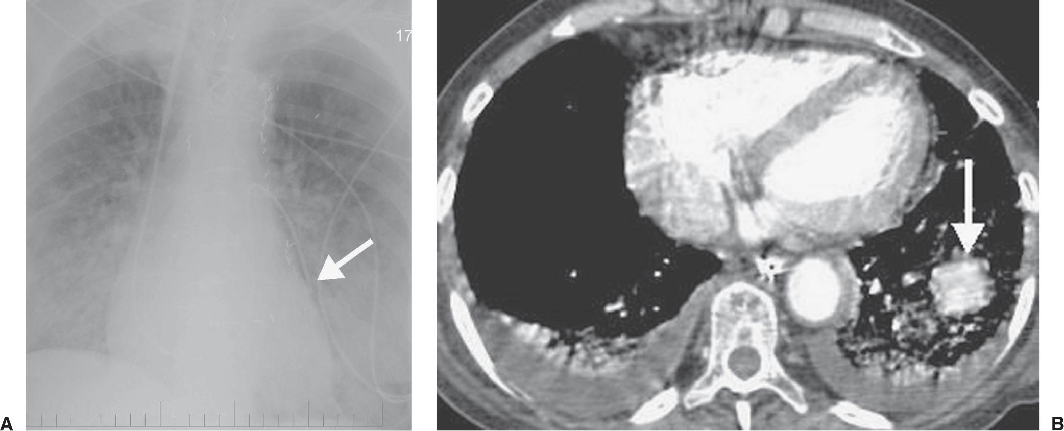
FIG. 5.13 • Pulmonary artery pseudoaneurysm as a complication of pulmonary artery catheter placement. A: AP chest radiograph shows pulmonary edema and the tip of a pulmonary artery catheter projected over an expected left lower lobe segmental pulmonary artery branch (arrow). B: The distal placement of the catheter tip resulted in perforation of a subsegmental pulmonary artery and development of a pulmonary artery pseudoaneurysm, shown as an enhancing mass in the left lower lobe on CT (arrow).
Table 5.2 COMPLICATIONS RELATED TO PULMONARY ARTERY CATHETER PLACEMENT
Related posts:
Stay updated, free articles. Join our Telegram channel

Full access? Get Clinical Tree


