Fig. 1.
Schematic overview of the ultrasound simulation set-up: geometry of the cardiac model (upper left), spherical wave transmit using a virtual source (upper right), example of multiple spherical wave imaging of the left ventricle (apical view) filled with scatterers (lower right) and resulting ultrasound image after coherent compounding (lower left).
The amount of spherical waves to be combined (s = 5), the opening angle θ (90°) and the size of the transmit subaperture (number of elements (n = 21) that are active for each spherical wave transmission) were chosen in accordance with the findings in [13, 14]. These settings ensure a good trade-off between lateral resolution, transmit pressure and frame rate. The individual spherical waves were transmitted at a pulse repetition frequency (PRF) of 2500 Hz. Element data of each spherical transmit were reconstructed into RF data using delay-and-sum beamforming. The grid for constructing the RF data was adjusted stepwise over imaging depth because of the depth dependent lateral resolution. Coherent summation of RF data from 5 spherical waves was then performed to obtain compounded RF data at an effective frame rate of 500 Hz. A schematic overview of the simulation set-up is shown in Fig. 1.
A 2D coarse-to-fine cross-correlation based displacement estimation algorithm [15] was used to compute axial and lateral inter-frame displacements. In the first ‘coarse’ iteration, large RF data kernels of 4 × 1.3 mm2 [axial x lateral] were used for cross-correlation calculation. The second iteration used a kernel size of 3 × 1.3 mm2 to obtain ‘finer’ displacement estimates. The axial kernel size corresponds to 78 (iter. 1) and 58 (iter. 2) RF data points respectively. As the grid for constructing the RF data was adjusted stepwise over imaging depth because of the depth dependent lateral resolution, the number of lines corresponding to 1.3 mm varies (stepwise) over imaging depth.
As no phase information is available in the lateral direction, lateral displacement estimation is by definition less accurate than axial displacement estimation. Lateral displacements were estimated at a 10 times lower frame rate (i.e., 50 Hz) to obtain higher displacements between frames and thus more robust estimates. Cumulative displacements were derived from the inter-frame displacements using bilinear interpolation to track the cardiac tissue over time. Tracking was started at end-diastole. A comparison was made between the cumulative axial and lateral displacement estimates and ground truth displacement values directly derived from scatterer positions in the myocardial tissue over the entire cardiac cycle.
3 Results
To evaluate the deformation estimation technique using high frame rate imaging, cumulative displacement estimates were compared to ground truth displacements as obtained from the model. Figure 2 shows the cumulative axial displacement estimates (upper panel) and ground truth cumulative displacements (lower panel) for 6 characteristic phases of the cardiac cycle. In Fig. 3, the lateral displacement estimates (upper panel) and ground truth values (lower panel) are depicted for the same cardiac phases. To gain more insight in the performance of the deformation estimation algorithm, root-mean-squared-errors (RMSEs) were computed between estimated and ground truth cumulative displacement values for each frame in the cardiac cycle. Resulting RMSE curves (solid lines) are given in Fig. 4. This figure also shows the maximum cumulative displacement values over the cardiac cycle to allow better interpretation of the RMSE values. It can be derived from this figure (left panel) that RMSEs for the cumulative axial displacement estimates are small (<1.2 mm). RMSEs for cumulative lateral displacement are below 1.3 mm, however the relative lateral RMSE values (compared to maximal cumulative displacement value) are larger than the relative axial RMSEs.
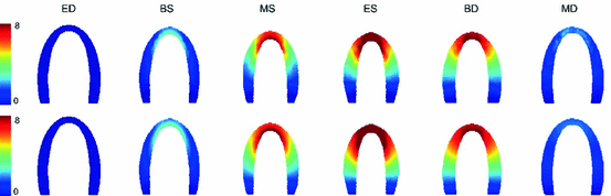
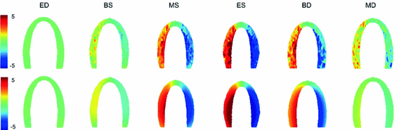
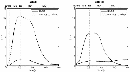
Fig. 2.
Cumulative axial displacement estimations [mm] (upper panel) for selected frames over the cardiac cycle. Lower panel: cumulative axial displacements [mm] as derived directly from the finite element model (ground truth).
Fig. 3.
Cumulative lateral displacement estimations [mm] (upper panel) for selected frames over the cardiac cycle. Lower panel: cumulative lateral displacements [mm] as derived directly from the finite element model (ground truth).
Fig. 4.
 Differences in Anatomical Remodelling of the Systemic Right Ventricle
 of Clinical Information from Cardiac MRI Using Manifold Learning
 Farnebäck Optic Flow for Extended Field of View of Echocardiography
 and Biomechanics Inspired Integration of Shape and Speckle Tracking for Cardiac Deformation Analysis
 Stiffness Estimation: A Novel Cost Function for Unique Parameter Identification
 of the Electrocardiography Inverse Solution to the Torso Conductivity Uncertainties


Comparison between ground truth cumulative displacement values and cumulative displacement values computed by the high frame rate deformation estimation method. Root-mean-squared-errors [mm] are shown (solid) and related to the maximum absolute cumulative displacement value [mm] (dashed) for each frame in the cardiac cycle.
Related posts:
Differences in Anatomical Remodelling of the Systemic Right Ventricle
Stay updated, free articles. Join our Telegram channel
Full access? Get Clinical Tree
