(1)
where h is the Planck’s constant (h = 6.626 × 10⁻³⁴ J s); γ is the nucleus-dependent gyromagnetic ratio (for 1H, γ = 42.6 MHz/T). We can also write

(2)
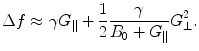
 is the characteristic Larmor frequency, a fundamental concept in NMR and MRI; a photon at this frequency can induce a transition from the lower to the higher energy state, or conversely, as we describe later, a nucleus emits a photon at this frequency when switching from the higher to the lower energy state. For a 1H nucleus in a 1-T magnetic field, the Larmor frequency is 42.6 MHz.
The equilibrium distribution of spins in an external magnetic field follows Boltzmann statistics such that we find an excess of spins in the lower energy state. If N 0 is the total number of spins, this excess can be described as

where k is the Boltzmann constant (k = 1.381 × 10⁻²³ J/K) and T is the absolute temperature.
(3)
Here we meet the first challenge of ultra-low-field MRI. At room temperature (300 K) and in the strong magnetic field of 1 T, this excess is only about 0.0007 %. Thus, the resulting magnetization is very small and the signals measured are rather weak. This explains why almost every practical implementation of NMR and MRI involves a large magnetic field, and the overwhelming technological trend is toward higher fields. For example, 3 T is now routinely used in clinical MRI.
When the sample (or subject) is placed in an external magnetic field, the magnetization takes some time to develop. This step is referred to as polarization. To follow the usual NMR convention, we define the magnetic field to be along the z axis. The magnetization will develop toward the equilibrium as
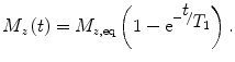
(4)
The equilibrium magnetization is
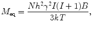
where N is the number of spins being measured, and I is the spin number (I = ½ for 1H). For example, for 1 cm2 of water (N = 6.69 × 10²² proton spins) at 300 K in a 1-tesla field, M eq ~ 3.2 × 10⁻⁹ J/T. Again, if the magnetic field is smaller by a factor of 100, the magnetization (and thus signal amplitude) will also be smaller by a factor of 100. As shown in Eq. (4), the magnetization (or sample polarization) builds up inverse-exponentially. The characteristic time constant of this process is known as the T 1, or spin–lattice, relaxation time. T 1 is a powerful probe of chemical environment, providing means to discriminate between tissue types (e.g., Damadian et al. 1971). As we will discuss later, T 1 depends on the magnetic field strength as well, and hence may contain unique information in the ULF regime.
(5)
Once the sample is magnetized, one can manipulate this magnetization to produce a measurable signal. The first step is to orient a proportion of the magnetization off the axis of the magnetic field. Any component of the spins tipped off-axis will begin to rotate, or precess, at the Larmor frequency and emit a signal at that frequency. For example, if the magnetic field is along the z axis, precession will be in the x–y plane. During precession, the spins experience magnetic field inhomogeneities associated with their chemical environment (as well as the local ambient environment) that will slightly shift the local Larmor frequency and thus cause spin dephasing and therefore loss of signal. The rate at which the transverse signal decreases is
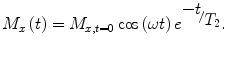
M x,t=0 is the initial magnetic moment transverse to the magnetic field, the cosine term describes rotation at the Larmor frequency and T 2 is the characteristic dephasing, or spin–spin, relaxation time.
(6)
and T 2 is the characteristic dephasing, or spin–spin, relaxation time.There is a fundamental difference between ULF and high-field (HF: B > 1 T for this discussion) NMR and MRI. In HF, the process of polarization, magnetization reorientation, spin evolution, and measurement all occur within a single magnetic field provided (typically) by a large superconducting magnet. At ULF, however, these fields may all be different and produced by different magnets.
Because the magnetization and thus signal is proportional to the field, one strategy is to use pre-polarization in a higher field (B p ~ 1–200 mT) followed by readout in a much lower measurement field (B m ~ 1–200 μT). Thus, T 1 in Eq. (4) refers to T 1 in the polarization field (B p). However, T 2 in Eq. (6) will be that in the B m field. Also, the values of precession are given by f = γB m, where B m is the μT-level measurement field.
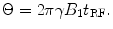
There are also differences in approaches to spin re-orientation (e.g., how precession is started, or how subsequent manipulations of the magnetization are accomplished) between conventional high-field (HF) MRI and the ULF MRI approaches. In HF MRI, spin re-orientation is typically accomplished by a time-varying magnetic field applied at the Larmor frequency, in a direction orthogonal to the direction of magnetization. This field is usually designated as B 1. The relation between B 1, the duration of its application t RF, and angular tip of the magnetization Θ is given by
(7)
Note that in HF MRI, B 1 is chosen to match the fixed Larmor frequency of the scanner. But in ULF MRI, we can either perform the spin flip in B p or B m, depending on the pulse sequence we have chosen.
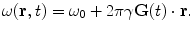
Typically we aim at Θ = 90° to produce the maximum signal in the x–y plane, where detection occurs. However, there is another method of spin reorientation that takes advantage of the flexibility of ULF MRI magnetic field generation. In many ULF-MRI configurations, B p and B m are orthogonal. Thus, one can simply begin precession by a rapid (non-adiabatic, dB p/dt ≫ γB m 2) shut-off of B p. In a non-adiabatic process, the magnetization cannot follow the field change, and is left aligned orthogonal to B m. Precession will then begin automatically, without a B 1 pulse. Figure 1 illustrates both approaches.
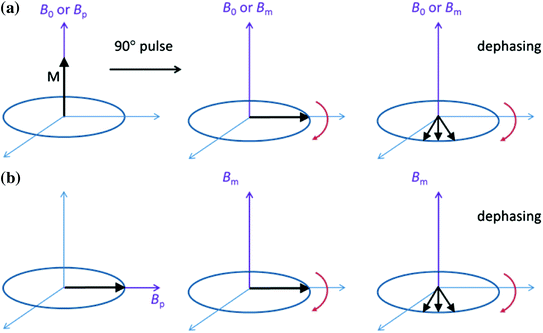
Fig. 1
Two methods for beginning precession. a The traditional 90° spin flip, possible both in HF and ULF MRI. In ULF MRI, the fields for polarization, spin flip, and precession may be of different amplitudes (and orientations, not shown here). In HF MRI, the fields are the same. b After polarization B p is removed non-adiabatically and B m is applied orthogonally. Precession begins immediately
Once precession has begun, detection of the magnetization can begin. In HF MRI, the typical scanner strengths are 1.5 or 3 T. This translates to a proton Larmor frequency of 64 or 128 MHz. A tuned induction coil is highly sensitive in this range. However, in ULF MRI precession occurs in the B m field, typically on the order of 100 μT, corresponding to a Larmor frequency of 4.26 kHz.
In conventional MRI with a Faraday coil, the signal scales as B 2, one order arising from the magnetization being proportional to B and one for the induced signal being proportional to the Larmor frequency. However, this relationship no longer holds once we are limited by the body noise, which is typically above about 10 MHz (Myers et al. 2006). While pre-polarization is an approach to improve the former factor (Macovski and Conolly 1993), using an ultra-sensitive detector such as the SQUID is a way to mitigate the latter. SQUIDs, broadband detectors with unsurpassed sensitivity of about 1 fT/√Hz in the frequency range of ULF MRI, are almost two orders more sensitive than a Faraday coil in this regime (Myers et al. 2006; Matlashov 2011). Because the SQUID is also the detector of choice for MEG, the combination of MEG and ULF MRI in a single device becomes obvious. We should, however, mention that getting a SQUID to work in the dynamic environment of MRI, even at ultra-low fields, is quite challenging. We will discuss some of the basic hardware considerations in Sect. 2.3.
2.2 Basic Principles of Image Acquisition
The physical principles between ULF and HF MR imaging are quite similar. Here we review a few basic concepts that will help us understand the differences. An excellent and far more complete description of imaging principles in the context of conventional MRI is provided by Callaghan (1991).
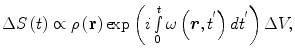
MRI is the spatial encoding of the NMR properties (e.g., T 1, T 2, or spin density). Encoding is based on the variation of the Larmor frequency within the applied field, see Eq. (2). A magnetic field gradient G(t) (assumed to be spatially linear for these discussions) is applied, causing the local Larmor frequency to vary such that
(8)
The NMR signal ΔS(t) from a single voxel (ΔV) will be (neglecting relaxation)
where ρ(r) is the spin density, and ω(r,t′) is the angular Larmor frequency. In Eq. (9), we assume that B 0 does not vary with time or position during the measurement. However, the ability to manipulate the measurement field in strength and orientation between measurements to extract different information from the image is a feature of ULF MRI that is typically absent in high-field MRI.
(9)
The signal from the whole sample, assuming here uniform detector sensitivity, becomes
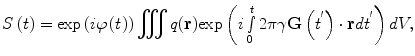
where q(r) is the spin density containing contrast information on local spin density ρ(r) and, when a suitable preparatory sequence is used, relaxation times T 1(r) and T 2(r), and/or diffusion coefficient D(r). The time-varying phase, φ(t), is the integral over the main Larmor frequency. Here we assume that the signal is obtained from the entire sample.
(10)
We next introduce the concept of the reciprocal space vector (Ljunggren 1983; Twieg 1983)
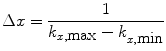
and we re-write Eq. 10 as (Callaghan 1991)
and
(11)
(12)
(13)
Equations (12) and (13) are a fundamental formulation in MRI. They comprise a Fourier transform pair showing that the signal and spin density are mutually conjugate. The MRI pulse sequence can then be thought of as a trajectory through k-space, where the gradient is analogous to velocity. How we apply the gradients will determine the course through image acquisition (Callaghan 1991).
Arising from this formulation, we can next consider two concepts that are critical to understanding image quality—spatial resolution and field of view (FOV). We will see that in addition to lower polarization leading to lower signal, the lower strength of imaging gradients also poses a unique new challenge for ULF MRI in terms of image acquisition time.
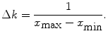
The Fourier transform pair (12) and (13) defines the relationship between the spatial and frequency domains. It follows from the Nyquist theorem that for any real signal (using the x, or readout, direction as an example)
and
(14)
(15)
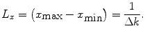
Equation (14) shows that the spatial resolution is related to the extent (k min … k max) of the image in the k-space. Equation (16) shows that the spatial extent of the image (x min … x max), or FOV, is related to the resolution in the k-space.
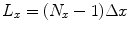
If the gradient does not change when it is switched on, the acquisition time t a , Eq. (11) becomes
(17)
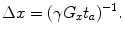
Thus we can describe the spatial resolution as
(18)
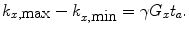
Spatial resolution in other directions can be derived similarly. As can be seen from Eq. (18), to improve the spatial resolution, one either has to increase the gradient or the acquisition (or encoding) time. The gradients in ULF MRI are typically on the order of 10–4 T/m. This is about 1/100 of those used in HF MRI. Thus, if we want to keep the same resolution as in HF MRI, with these weaker gradients we must increase the acquisition time by a factor of 100.
Why don’t we just increase the gradients? There are two reasons, the first being related to concomitant gradients. These are the unwanted magnetic fields, G ⊥, that inevitably arise in directions orthogonal to the measurement field B m and to the gradients which we deliberately apply for imaging,  . At a location within the imaging volume, these fields shift the frequency by
. At a location within the imaging volume, these fields shift the frequency by(19)
In HF MRI, these gradients can be neglected because the main magnetic field (B 0 > 1 T) is typically much higher than the gradients (10−2 T/m) such that G ∥/B 0 ≪ 1, G ⊥/B 0 ≪ 1, and thus frequency variations produced by the stray fields are small. However, in ULF MRI the main magnetic field B m ≈ 10−4 T and the gradients G ≈ 10−4 T/m, which generates a magnetic field variation of 0.2 × 10⁻⁴ T in a 20-cm FOV. The concomitant fields, not in parallel with B m, are of similar order of magnitude as G ∥. Thus, the frequency variations are non-negligible and the total magnetic field experienced by the spin system is no longer in a plane orthogonal to B m. In general, concomitant gradients can be accounted for with some effort (e.g. Volegov et al. 2005; Nieminen et al. 2010; Hsu et al. 2013), but they do pose a constraint.
The other reason that gradients cannot be arbitrarily strong is related to bandwidth. Consider a simple case: a HF MRI system with B 0 = 1 T and 10−2 T/m gradients. A 20-cm object would have a central frequency of 42.6 MHz and a frequency spread across the object of Δf ~ 85.2 kHz. However, if B m = 10−4 T and G = 10−4 T/m, the central frequency is 4.26 kHz and the frequency spread within a FOV of 20 cm is 852 Hz. If we turn up the gradients, we will further widen the frequency spread across the object and consequently need to measure part of the MRI signal in the challenging concomitant-field regime.
Thus, our only choice to maintain spatial resolution at ULF appears to be longer acquisition times. But at ULF, the T 1 and T 2 times for many interesting tissues are approximately of the length required for t a (Zotev et al. 2009), so we are also running out of signal at the same time. We note that Eq. (18) is applicable only when the SNR is sufficient, usually >5 (Matlashov et al. 2012). We can write SNR as (Myers et al. 2006)
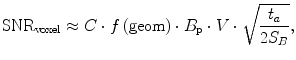
where C comprises the physical constants, f is a function of the geometry, S B is the magnetic noise spectral density, B p is the pre-polarization field, and V is the voxel volume. We note again that SNR is proportional to B p. As we mentioned previously, this is different from HF MRI where it scales as  (i.e.,
  ). This is also different than pulsed-field MRI using a Faraday coil (Matter et al. 2006), where SNR scales as B p B m. The reason for this is the broad-band sensitivity of the untuned SQUID. We are again reminded that higher pre-polarization (or lower sensor noise) will increase SNR, and smaller voxels will decrease it.
(20)
(i.e., ). This is also different than pulsed-field MRI using a Faraday coil (Matter et al. 2006), where SNR scales as B p B m. The reason for this is the broad-band sensitivity of the untuned SQUID. We are again reminded that higher pre-polarization (or lower sensor noise) will increase SNR, and smaller voxels will decrease it.Let us briefly return to the discussion of field-of-view (FOV). FOV is the spatial extent of our image, and is related to the spatial resolution by the number of steps, N. Again assuming the x-direction, we can write
(21)
A simple way to speed up imaging is provided by parallel imaging methods (Pruessmann et al. 1999). In this approach, the spatial sensitivity of an array of SQUIDs is used to replace spatial encoding steps. Using less encoding steps speeds up the acquisition but usually results in an aliased image. By using, for example, the sensitivity maps from an array of coils, a full image may still be reconstructed. In applications like combined MEG and MRI, where a SQUID array is available, this has been demonstrated as a viable approach (Zotev et al. 2008a). Some of the complications due to inductive coupling between tuned receiver coils in HF MRI parallel imaging are greatly reduced with untuned SQUIDs. However, it should be emphasized that parallel imaging accelerates the MRI acquisition at the cost of SNR, which is already scarce in ULF MRI.
Before we move on to a discussion of the ULF MRI instrumentation, we would like to mention briefly that in addition to providing a new regime of applications due to lower magnetic fields (namely the combination of MEG and MRI), ULF MRI also enables new opportunities for image contrast. As we mentioned, T 1 is a sensitive function of the magnetic field; there is evidence that T 1 contrast at ULF is different, and for some applications superior (Lee et al. 2005) to that at HF MRI. Of course, it is not just contrast but contrast-to-noise that must be considered, as we discuss at the end of Sect. 2.4.
2.3 ULF–MRI Instrumentation
In the discussion below we will generally assume that the application is for the combination of ULF MRI and MEG. Thus, we are assuming that ULF MRI is being done in the presence of a magnetically shielded room (MSR). We will also assume that we have an array of SQUIDs. We note that for applications of ULF MRI that do not include MEG, an MSR may not be required. For example, the Clarke group at UC Berkeley operates in an aluminum eddy current shield only. We also note that there has been progress using sensors other than SQUIDs (namely the atomic magnetometer) both for MEG (Xia et al. 2006) and ULF MRI (Savukov et al. 2009), which we will not discuss here.
In ULF MRI, one aims at the highest pre-polarization that can be tolerated (while maintaining the benefits of the ULF regime) and at the most sensitive sensor. The heart of any ULF MRI instrument is the SQUID sensor array. Large (hundreds of sensors) SQUID arrays have been used for decades for MEG (Hämäläinen et al. 1993). The noise level of a SQUID can be as low as 10−15 T, enabling it to detect the very weak (10−12–10−15 T) magnetic fields from brain activity from outside the head. A challenge for ULF MRI is that the changing magnetic fields are many orders of magnitude larger than the dynamic range of SQUIDs. Several strategies have been implemented to deal with this. One approach is to encapsulate the SQUID chips in sealed Pb boxes that have a critical field of about 80 mT. The SQUID can also be locally shielded by Nb plates on the chip (Luomahaara et al. 2011). In either case, the pick-up coil extends outside the shield to detect the fields of interest. Thus, the input coil circuit also needs current limiters. One can use externally controlled superconducting cryo-switches (Zotev et al. 2007), which become resistive when heated above the critical temperature and thereby make the pick-up coil much less sensitive to magnetic fields. Other groups have used arrays of Josephson junctions (Hilbert et al. 1985) that become resistive above the Josephson critical current and thereby limit the current.
To achieve a high pre-polarization field, a variety of magnet designs have been proposed. In some sense, generating B p is much simpler than at HF because the fields are so much lower and the field homogeneity requirement is less stringent (McDermott et al. 2002; Burghoff et al. 2005). B p can be relatively (a few percent) inhomogeneous compared to the parts-per-million or better requirement for B 0 in HF MRI.
However, there are considerations to producing (and removing) B p. In fact, some of the advantages (reduced homogeneity requirement, shorter T 1 times) can be disadvantages if not accounted for. The first consideration is that it is not trivial to make a pulsed field at >50 mT. The coil will heat up, dissipated energy must be removed, and the proximity of a large amount of conductor near the SQUIDs can introduce Johnson noise. The B p coil should be physically disconnected during the measurement (via a relay) to reduce the antenna effect.
There have been several approaches to producing a pulsed B p, including water-cooled (Myers 2006), coolant (Fluorinert) and liquid nitrogen (LN) cooled coils (Sims et al. 2010). The LN coil has the benefit of seven times lower resistance, but requires an additional cryostat. Recently, a self-shielded (Nieminen et al. 2011) pulsed superconducting coil (Vesanen et al. 2013) has been demonstrated for ULF MRI; the B p coil was integrated into the cryostat with the SQUIDs. The choice of materials for B p can be important. For example, we have found that multi-stranded Litz wire performs much better than solid wire in terms of noise. According to Vesanen et al. (2013), the superconducting wire magnetized if too high of a current (>12 A) was applied, producing spurious gradients that influenced the image quality, limiting B p in that work to <24 mT.
Perhaps the most challenging aspect of a pulsed B p is how to turn it off appropriately. When the B p field changes transient eddy currents will be induced in nearby conductors, which can impose a long dead-time if the magnetic fields from the transients exceed the dynamic range of the SQUIDs.
There are two approaches to switching off B p: adiabatic and non-adiabatic. In a non-adiabatic ramp-down, dB p/dt ≫ γB m2 such that the magnetization is left aligned with the original direction of B p. If B m is orthogonal to B p, precession will begin automatically. In principle, this approach can minimize the time between beginning precession and measurement. In reality, however, the faster the ramp-down of B p, the larger are the transients that are induced in nearby conductors. When measurements are made inside a conductive MSR, these transients can become a serious confound as they may have components that persist for hundreds of ms (Vesanen et al. 2012) and are inherently low frequency and hard to de-convolve from the MEG. Even in the absence of an MSR, anything conducting nearby will also support transients that may impact the image and/or impose long wait times. One added consideration in the non-adiabatic field removal is the non-uniformity of B p. Not requiring a uniform B p greatly simplifies the magnet design, but signal is lost because of this non-uniformity; when precession starts, the spins are not all in phase. In addition, there are technical problems associated with the requirement to dissipate the energy stored in the B p coil.
If, instead, an adiabatic ramp (dB p/dt ≪ γB m2) is used, the final magnetization will be aligned with the low B m field, which is easy to make uniform. Further, phase coherence is typically improved due to lack of transients. A spin-flip pulse is then required to start precession. In an adiabatic ramp, dB/dt is lower and thus there is less danger of heating metallic implants or affecting therapeutic electronic devices the subject may be carrying. This is a special consideration when imaging near metal. In an ULF MRI system, B p is typically 10–200 mT and it is removed within 10–100 ms (depending on the approach). Thus, the field change dB/dt may range from 0.1 to 20 T/s. Even with relatively high pre-polarization, the dB/dt in a ULF MRI system is typically lower than that produced by the switching gradients in HF MRI systems. However, the adiabatic ramp-down takes longer, and signal is lost due to T 1 relaxation during that time.
The self-shielded design of Nieminen and colleagues (2011) is an especially appealing approach because it largely eliminates the origin of the transients. The pre-polarization field is reduced only by 10 %, but the fields at the walls of the MSR are reduced by as much as 90 %. This approach is likely critical to achieving successful field pulsing inside an MSR.
Before we leave our discussion of B
 Decoding and Brain Machine Interfaces Based on Electromagnetic Oscillatory Activities: A Challenge for MEG
Neuroscience: A New Frontier for Magnetoencephalography?
Decoding and Brain Machine Interfaces Based on Electromagnetic Oscillatory Activities: A Challenge for MEG
Neuroscience: A New Frontier for Magnetoencephalography?
 Integration
 Imaged Pathways of Stuttering
 Current Imaging with Ultra-Low-Field NMR Techniques
 Concurrent EEG and fMRI Intrinsic Networks


Related posts:
Decoding and Brain Machine Interfaces Based on Electromagnetic Oscillatory Activities: A Challenge for MEG
Neuroscience: A New Frontier for Magnetoencephalography?
Integration
Imaged Pathways of Stuttering
Stay updated, free articles. Join our Telegram channel
Full access? Get Clinical Tree
