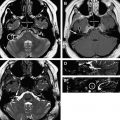
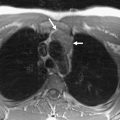
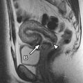
The normal MR imaging appearance of the neck can be confusing given the number and complexity of structures that pass through it. This article strives to simplify normal MR imaging anatomy of the neck using a spatial approach. We present the protocols used at our institution and provide tables with details. Magnetic resonance (MR) imaging anatomy and appearance of the deep spaces of the neck are described with extensive labeled imaging correlates. Pearls and common pitfalls encountered with MR imaging of the neck are discussed. Additional aspects of normal neck MR imaging are described including lymph node, brachial plexus, and vascular anatomy.
The anatomy of the neck can be daunting for both radiologists and clinicians alike. Although small, the neck contains many vital structures. Therefore, mastery of its radiologic anatomy is essential for physicians evaluating for pathology. Magnetic resonance imaging (MR imaging) has become a vital tool to diagnose many disease processes affecting the neck region. Similar to computed tomography (CT), MR imaging has the advantage of cross-sectional imaging. Unlike CT, however, MR imaging does not require the use of intravenous contrast material to add soft tissue contrast, as the intrinsic signal characteristics of the interrogated tissues can often provide inherent differentiation. Moreover, when gadolinium contrast is required for MR imaging, it is generally considered safer than iodinated contrast used for CT, with a lower incidence of anaphylaxis and renal nephrotoxicity in patients with impaired renal function.
Additionally, MR imaging does not carry the burden of radiation exposure, which can become problematic for patients undergoing multiple CT scans throughout life, particularly considering the relative radiosensitivity of the thyroid gland. To spare ionizing radiation exposure, MR imaging of the neck can be performed in children, who are especially sensitive to the effects of repeated exposure. However, in very young children, general anesthesia is typically administered to prevent significant motion degradation. Therefore, the risks and benefits of MR imaging in young children must be weighed accordingly. MR imaging is advantageous in that multiplanar imaging can be easily performed without needing to reposition the patient, allowing for improved differentiation of masses, vessels, and soft tissue.
The suprahyoid neck is best imaged by MR imaging, as it is less affected by dental amalgam as compared with CT. Ultrasound may be used to evaluate the carotid arteries and thyroid gland, but cannot penetrate deeply enough to evaluate the visceral structures of the neck. Since the advent of MR imaging, serial improvements in spatial resolution and protocol technique have allowed for proper evaluation of normal anatomy, as well as the full array of pathology. This article describes the protocols used at our institution and the normal neck anatomy seen with current MR imaging techniques. Correlative imaging examples are provided as well.
Many systems are used for classifying and organizing the neck structures. This article approaches the neck from a neck space perspective. The neck space concept is a commonly used method to assist radiologists in organizing the neck and establishing appropriate differential diagnoses for pathology discovered within a specific space of the neck. For imaging purposes, the boundaries of the neck are considered to be the mandible and the mylohyoid muscles anterosuperiorly, the base of the skull posterosuperiorly, the scapulae posteroinferiorly, and the thoracic inlet (sternum, first ribs, first thoracic vertebra) centrally at the inferior aspect.
Protocol
Most neck MR imaging examinations performed at our institution follow a standard “General Neck” protocol, typically performed on a 1.5-Tesla magnet, although 3.0-Telsa examinations can provided increased spatial and contrast resolution ( Table 1 ). For all neck imaging, the patient is placed head first and supine into the magnet. A neurovascular array coil is placed on the patient. We use a 20-cm to 23-cm field of view (FOV), 5-mm to 6-mm slice thickness, and 1-mm to 2-mm interscan spacing. A wide range of matrices are used (see Table 1 ). First, a sagittal T1 sequence is obtained using a spin-echo pulse sequence from the clivus to the thoracic inlet, providing information about the pre-epiglottic space and the nasopharynx. Next, axial fluid-attenuated inversion recovery (FLAIR) and diffusion sequences are obtained through the entire brain. Then, an axial T2 fat-saturated fast spin-echo (FSE) sequence is performed from the clivus to the thoracic inlet, followed by an axial T1 FLAIR sequence, which is the best sequence for establishing anatomic relationships and identifying pathology within fat. FSE imaging provides the added benefit of a relatively short acquisition time limiting motion degradation, reduced magnetic susceptibility artifacts, and improved patient tolerance. Moreover, spin-echo techniques have high signal-to-noise ratios and therefore superior spatial resolution, as compared with inversion recovery sequences. Next, an axial dynamic spoiled gradient sequence is obtained from the skull base to the bottom of the hyoid bone following the administration of intravenous gadolinium. Then, sequential postcontrast axial T1 FLAIR and axial T1 fat-saturated images are obtained from the clivus to the thoracic inlet. Fat saturation assists in elucidating adenopathy, as well as enhancing mass lesions, which may otherwise be obscured by bright fat. Finally, an axial T1 postcontrast sequence is obtained through the brain.
| 1.5 Tesla | T1, SE | Diffusion Brain | T2-FLAIR | T2-Fat Sat, FSE | T1-FLAIR | Dynamic SPGR | T1-FLAIR | T1-Fat Sat, SE | T1, SE Brain | T1, SE a | T1, SE a |
|---|---|---|---|---|---|---|---|---|---|---|---|
| TR, ms | 600 | 10,000 | 10,000 | 3000–5000 | 1600–2500 | 230–305 | 1600–2500 | 500–700 | 500–700 | 500–700 | 450–700 |
| TE, ms | Min.Full | Minimum | 100 | 98 | 24 | In Phase | 24 | Minimum | Min.Full | 19.23 | 19.23 |
| TI, ms | — | — | 2200 | — | — | 90 | — | — | — | — | — |
| Slice, mm | 5 | 6 | 6 | 5–6 | 5–6 | 4–5 | 5–6 | 5–6 | 6 | 3 | 3 |
| Interscan spacing, mm | 1.5 | 0 | 1.5 | 1.5–2 | 1.5–2 | 1 | 1.5–2 | 1.5–2 | 1.5 | 0.5 | 0.5 |
| Gadolinium | Pre | Pre | Pre | Pre | Pre | Post | Post | Post | Post | Pre | Post |
| Acquired planes | Sagittal | Axial | Axial | Axial | Axial | Axial | Axial | Axial | Axial | Coronal | Coronal |
| Matrix, freq. | 512 | 128 | 256 | 512 | 256 | 256 | 512 | 256 | 256 | 256 | 256 |
| Matrix, phase | 256 | 128 | 192 | 256 | 192 | 128 | 256 | 192 | 192 | 256 | 256 |
| FOV, cm | 20 | 22 | 23 | 20 | 20 | 20 | 20 | 20 | 23 | 20 | 20 |
| Signal Averages | 2NEX | 1NEX | 1NEX | 3NEX | 3NEX | 1NEX | 3NEX | 2NEX | 1NEX | 2NEX | 2NEX |
a Part of the nasopharynx protocol, imaged from posterior globe to posterior spinal cord in anteroposterior dimension and the top of frontal sinus to C1 in craniocaudal dimension.
Our institution also offers a “Larynx” protocol with a smaller FOV (18–20 cm) and smaller slice thickness (3–5 mm as compared with 5–6 mm for the general neck protocol). This sequence also provides smaller interscan spacing (0.5–1.5 mm). First, a sagittal T1 sequence is performed followed by axial T1 and T2 sequences. These images are obtained from the bottom of the pituitary gland to the thoracic inlet. Next, the axial T1 larynx sequence is performed from the hyoid bone to the thoracic inlet followed by postcontrast axial T1 fat-saturated images, both at 3-mm slice thickness. Finally, delayed axial T1 postcontrast standard and fat-saturated sequences are obtained at 5-mm slice thickness. A 256 × 256 matrix is used for the infrahyoid neck to increase the signal-to-noise ratio ( Table 2 ). The neck surface coil is vital to infrahyoid neck imaging, as is adequate motion suppression.
| 1.5 Tesla | T1, SE | T1, SE | T2, SE | T1, SE | T1-Fat Sat, SE | T1, SE | T1-Fat Sat, SE |
|---|---|---|---|---|---|---|---|
| TR, ms | 625 | 500–700 | 3000–5000 | 400–500 | 600–750 | 625 | 575 |
| TE, ms | Minimum Full | Minimum | 102 | Minimum Full | Minimum | Minimum Full | Minimum |
| TI, ms | — | — | — | — | — | — | — |
| Slice, mm | 4 | 5 | 5 | 3 | 3 | 5 | 5 |
| Interscan spacing, mm | 1 | 1.5 | 1.5 | 0.5 | 0.5 | 1.5 | 1.5 |
| Gadolinium | Pre | Pre | Pre | Pre | Post | Post | Post |
| Acquired planes | Sagittal | Axial | Axial | Axial | Axial | Axial | Axial |
| Matrix, freq. | 512 | 448 | 448 | 256 | 512 | 448 | 512 |
| Matrix, phase | 256 | 256 | 256 | 256 | 256 | 256 | 256 |
| FOV, cm | 20 | 18 | 18 | 18 | 18 | 18 | 18 |
| Signal averages | 2NEX | 2NEX | 3NEX | 2NEX | 2NEX | 2NEX | 2NEX |
Additional “nasopharynx” T1 spin-echo precontrast and postcontrast sequences are obtained in the coronal plane using the thinner slice thickness and interscan spacing described previously (see Table 1 ).
Typically, imaging of the suprahyoid neck requires only a standard head coil, whereas the infrahyoid neck requires a dedicated neck coil. The use of surface coils may improve spatial resolution, but at the cost of anatomic coverage. Water bags may be placed on either side of the patient’s neck to reduce magnetic susceptibility artifact.
Anatomy
The hyoid bone is used as a landmark to divide the neck into the suprahyoid and infrahyoid neck ( Fig. 1 A). The suprahyoid neck can be further subdivided into the following spaces: parapharyngeal space, pharyngeal mucosal space, masticator space, parotid space, sublingual and submandibular spaces, and the buccal space. There are spaces that are common to both the suprahyoid and infrahyoid neck, including the carotid space, retropharyngeal/danger space, perivertebral space, and the posterior cervical space. Finally, the visceral space is located solely within the infrahyoid neck.
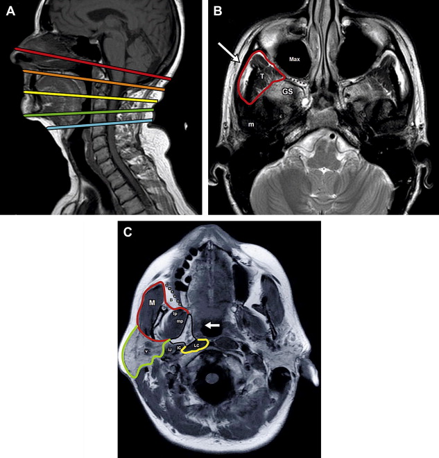
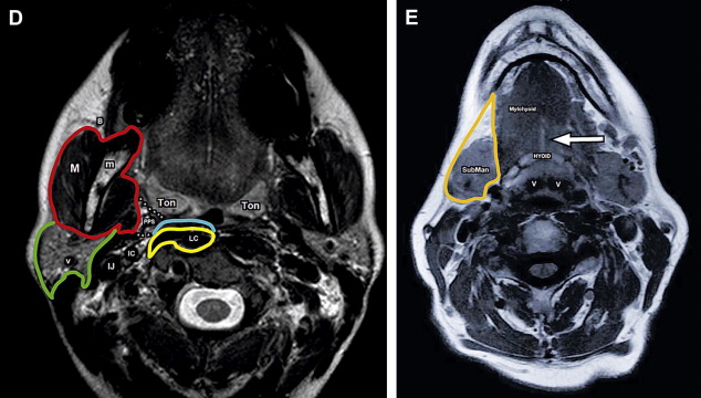
Deep cervical fascial planes are used to divide the neck further into deep fascial spaces. The deep cervical fascia is made up of 3 layers: a superficial layer, a middle layer, and a deep layer. The spatial resolution of MR imaging does not allow direct visualization of the fascia itself, but knowledge of the fascial layer’s course provides a manner by which to divide the neck into the deep fascial spaces with cross-sectional imaging. Of note, the superficial fascial layer is a separate layer not included within the 3 sublayers of the deep cervical fascia and consists of the subcutaneous tissues of the head and neck. The platysma and muscles of facial expression are embedded within this fascial layer, along with vessels, superficial lymph nodes, and cutaneous nerves.
Anatomy
The hyoid bone is used as a landmark to divide the neck into the suprahyoid and infrahyoid neck ( Fig. 1 A). The suprahyoid neck can be further subdivided into the following spaces: parapharyngeal space, pharyngeal mucosal space, masticator space, parotid space, sublingual and submandibular spaces, and the buccal space. There are spaces that are common to both the suprahyoid and infrahyoid neck, including the carotid space, retropharyngeal/danger space, perivertebral space, and the posterior cervical space. Finally, the visceral space is located solely within the infrahyoid neck.

Stay updated, free articles. Join our Telegram channel

Full access? Get Clinical Tree


