Nuclear Imaging—The Gamma Camera
18.0 INTRODUCTION
The focus of this chapter is the underlying principles and components of the gamma camera and its use in planar single photon nuclear imaging. Clinical understanding includes that of the photon detector itself; conversion of radioactive decay parent gamma-ray (γ-ray) (or decay daughter x-ray) photon interaction into deposited energy and spatial position; collimation; imaging performance characteristics and their measurement; quality control; and incorporation of digital computers and modes of acquisition.
18.1 PLANAR NUCLEAR IMAGING: THE ANGER SCINTILLATION CAMERA
The gamma camera most commonly used for nuclear imaging is the so-called Anger camera, named after its inventor, Hal O. Anger. It is also called a scintillation camera, as it employs a thallium-activated sodium iodide [NaI(Tl)] crystal that converts the energy of an incoming x- or γ-ray into secondary, blue visible to ultra-violet range scintillation photons, from which energy deposited and spatial (x–y) position are obtained.
a. Modern camera: a rectangular crystal, typically 0.95 cm (3/8 inch) or 1.59 cm (5/8 inch) thick, with dimensions/field-of-view (FOV) of approximately 59 cm × 44 cm/54 cm × 40 cm (21 inch × 15.5 inch).
b. A large number (59 to 91) of 5.1-cm to 7.6-cm (2- to 3-inch) diameter photomultiplier tubes (PMTs) optically coupled to the crystal.
c. A Lucite light pipe between the crystal’s rear glass window and the PMTs, to improve the spatial uniformity of the light response function. (Some camera designs employ a so-called “digital” light pipe, where the PMTs are directly coupled to the glass window and digital circuitry performs the function of a physical light pipe.)
d. PMT analog output signal preamplifiers.
e. A collimator, usually made of lead, that only allows x- or γ-rays approaching from certain directions to reach the crystal.

▪ FIGURE 18-1 The components of an Anger scintillation camera. F. 18-2
2. Anger logic: algorithm using circuitry that converts PMT preamplifier outputs from an incoming photon interaction to event energy and x–y position (Fig. 18-2). Energy is the simple sum of PMT signals, and x and y are distance-from-center weighted sums of PMT signals.

▪ FIGURE 18-2 Electronic circuitry of a modern Anger scintillation camera. Modern cameras are digital, whereby the analog pulses from the PMTs (see Fig. 18-1) are converted to digital signals for computing event energy and spatial location and applying energy and spatial linearity corrections. (An actual camera has many more than four PMTs and ADCs.) F. 18-3
3. Collimator: device that allows image formation by restricting photons reaching the detector to only those from certain directions (projection by absorption technique).
a. Most collimators are constructed of lead, with tungsten as the alternative.
b. Spatial resolution and sensitivity are controlled by hole diameter, length, and septal thickness.
c. Septal penetration decreases with decreasing photon energy and increasing septal thickness.
d. Classes of collimators (Fig. 18-3): parallel-hole (general-purpose, magnification m = 1); pinhole (thyroid imaging, image inverted, m >> 1 decreases and FOV increases with distance d); converging (small object imaging, m > 1 increases and FOV decreases with d); diverging (imaging of objects larger than the detector physical FOV, m < 1 decreases and FOV increases with d).
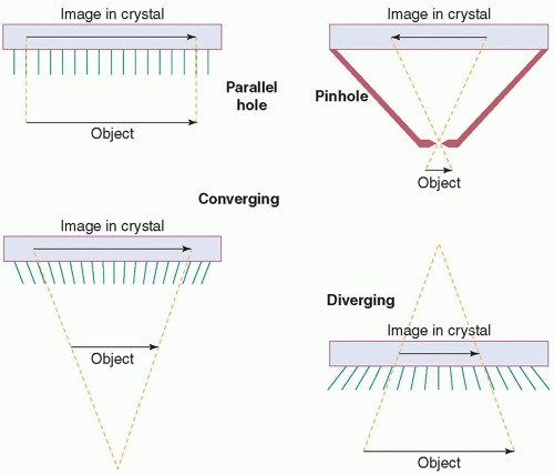
▪ FIGURE 18-3 The four classes of gamma camera collimators, and their effect on field-of-view and magnification and orientation of the image of an object. F. 18-4
4. Multielement camera: is an alternative detector design, consisting of a two-dimensional array of independently functioning small crystals (pixels); either NaI(Tl) or CsI(Tl) coupled to either position-sensitive PMTs or a matched array of photodiodes (indirect conversion to position and energy electronic signals) or CZT solid state detectors (direct conversion to position and energy).
5. Performance: characteristics of a gamma camera are as follows:
a. Energy resolution (intrinsic detector)
b. Detection efficiency (product of intrinsic photopeak and collimator geometric)
c. Sensitivity (system)
d. Spatial resolution (intrinsic and system including the effect of the collimator)
e. Uniformity (intrinsic, and system including the effect of the collimator)
f. Spatial linearity (intrinsic; Anger camera only)
g. Count rate/dead-time (multielement camera maximum count rate much higher than Anger)
h. Multiple-window spatial registration (for imaging 67Ga, 111In; Anger camera only)
6. Design factors determining performance: include choice of crystal material (NaI(Tl), CsI(Tl) or CZT) and thickness; number, shape and size of PMTs (Anger camera) or detector pixel size (multielement); collimator material (lead or tungsten), hole area A (i.e., shape and diameter), length (l) and septal thickness (t); energy, linearity and uniformity corrections; and analog-to-digitial signal processing conversion point (PMT output or downstream)
a. Energy resolution (99mTc 140 keV) is approximately 6% for CZT, approximately 8% for CsI(Tl) and approximately 10% for NaI(Tl); and generally improves with increasing photon energy.
b. Efficiency decreases with decreasing crystal thickness and increasing photon energy (Fig. 18-4).

▪ FIGURE 18-4 Calculated photopeak efficiency of NaI(Tl) as a function of x- or γ-ray energy and crystal thickness. F. 18-10
c. Geometric efficiency of a parallel-hole collimator is approximated as: ; A = hole area, l = hole length, g = FOV fraction not covered by septa. Increased
EC = decreased spatial resolution (FWHM ∝ A/l), and vice versa (pinhole EC decreases, converging EC increases, and diverging EC decreases, with distance).
d. System resolution (FWHM) degrades with distance (Fig. 18-5), as RI is intrinsic and R‘C is collimator (≈d[leff + b]/(leffm); d = hole diameter, leff = effective hole length, b = source distance). m = 1 (parallel-hole), f/(f − x) (converging), f/(f + x) (diverging), f/y (pinhole); f = crystal-to-focal point, x = crystalto-object, y = focal point-to-object.
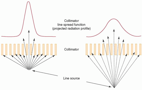
▪ FIGURE 18-5 Geometric resolution of a parallel-hole collimator degrades with increasing distance from the object being imaged. The LSF FWHM increases linearly as a function of distance. However, the total area under the LSF varies little, resulting in essentially constant sensitivity regardless of distance from the object. As a consequence, system resolution degrades linearly with distance, as its FWHM is the square root of the sum of the squares of the intrinsic (constant) and collimator FWHMs. F. 18-11
e. Uniformity variation is inherent in all gamma cameras; intrinsic due to variations in total signal output for a given energy deposition, and system due to both variations in crystal efficiency and collimator septa and imperfections. Spatial nonlinearity is inherent in an Anger camera, due to the nonlinear signal response of a PMT versus event distance from its center. Thus, energy, linearity, and uniformity corrections are required. Figure 18-6 shows example images with corrections off (top) and on (bottom). Figure 18-7 shows schematics of nonlinearity and energy corrections.

▪ FIGURE 18-6 Left to right. Example Anger scintillation camera uniform flood, lead-slit mask and orthogonalhole pattern images without (top) and with (bottom) digital correction circuitry enabled. The necessity and effectiveness of energy (Z) and spatial linearity corrections to remove the inherent nonuniformities and spatial nonlinearities is demonstrated. F. 18-13

▪ FIGURE 18-7 Anger scintillation camera spatial linearity correction circuitry (top) and energy (Z) correction circuitry (bottom). Linearity and Z correction factors as a function of event location within the camera’s field-of-view are stored in look-up tables. F. 18-14 AND 18-16
7. Attenuation, scatter and collimator resolution: cause a nonideal two-dimensional projection gamma camera image of a three-dimensional object.
a. Attenuation reduces the number of photons reaching the detector exponentially as a function of depth in tissue (e-µx, where µ = attenuation coefficient [cm-1, decreasing with increasing photon energy, e.g., µTl-201 = 0.19 and µTc-99m = 0.15 for soft tissue] and x = cm depth).
b. Compton scatter photons in the patient may pass through the collimator holes and be detected, resulting in a loss of contrast and an increase in random noise. The energy window must be wide enough to capture the majority of the photopeak, a consequence of which is acceptance of narrow-angle scatter (CZT has better energy resolution than NaI(Tl), which allows a narrower energy window, and, thus, a reduced relative contribution of scatter).
8. Gamma camera routine quality control: consists of daily peaking and uniformity; weekly spatial resolution and linearity; and annual performance testing.
a. Peaking: centering energy window(s) on the photopeak(s) of a radionuclide. Daily adjustment or check of the Tc-99m or Co-57 photopeak is performed, using a scatter-free source; other radionuclides are peaked less frequently (e.g., after major calibration). Examples of centered (A, C) and shifted (B) Tc-99m 140 keV photopeaks are illustrated on the left side of Figure 18-8.
b. Uniformity (daily and after repair): assessment of the response of the detector to a uniform flux of photons. A Tc-99m or Co-57 point source (intrinsic uniformity) or Co-57 planar source (system uniformity) is used. Five to fifteen million counts are obtained, and images are evaluated visually and quantitatively (NEMA analysis). The uniformity test will reveal most malfunctions. The uniformity of each collimator should be evaluated periodically. Figure 18-8 upper right shows examples of good (A) and bad (PMT failure) (B) uniformity flood images.
c. Spatial resolution and spatial linearity (weekly): assessment of the ability of the camera to visualize small objects with correct spatial positioning (not applicable to a multielement camera). A four-quadrant bar phantom is typically used, imaged with four 90-degree rotations (alternating 180-degree horizontal and vertical flips) over every 4 weeks, to evaluate all quadrants of the camera equally. Since the bars are manufactured straight, spatial linearity is assessed at the same time. If system resolution is assessed, the same collimation is used every week. A Co-57 sheet source system resolution image of a bar pattern is shown on the lower right of Figure 18-8.

▪ FIGURE 18-8 Daily and weekly Anger scintillation camera quality control consists of “peaking,” uniformity, and resolution/linearity. The centering of the photopeak within either the Tc-99m or Co-57 camera’s energy window should be verified daily (before uniformity QC). Left. The Tc-99m 140 keV photopeak centered (A) and misaligned (B) within a 20% window, and centered with a 15% window (C). Upper right. Uniformity flood images from a dual-head gamma camera, where one head is normal (A) but a PMT in the other head was optically decoupled (B). Lower right. Image of a typical bar pattern, acquired extrinsically with a Co-57 uniform sheet source and LEHR collimation. F. 18-14, 18-18 AND 18-8C
d. Efficiency of each camera head should be measured periodically, by calculating the count rate per unit activity from the recorded number of counts and duration of an acquired image of a source of known activity in a consistent geometry.
e. Annual performance evaluation of each camera should be conducted, which includes peaking (all radionuclides imaged); uniformity; efficiency; spatial resolution; multienergy spatial registration (Anger cameras only); energy resolution; and count-rate performance. Relevant tests should also be performed after each repair or adjustment.
f. Acceptance testing of new cameras should be performed by an experienced medical physicist, to ensure the camera’s performance meets the purchase specifications prior to first clinical use and establish baseline values for routine quality control testing.
9. Computers, whole body scanning, and SPECT:
a. A digital computer is now used on all gamma cameras to
(i) Acquire, process and display digital images
(ii) Control camera head movement
b. Many large FOV gamma cameras can perform whole-body scanning:
(i) Some older systems: The camera moves past a stationary patient table (less floor space required).
(ii) Modern systems: The table and patient move past a stationary camera.
(iii) The position of the camera head relative to the patient table is sensed.
(iv) Values specifying the camera-relative-to-table position are added to X–Y position signals.
(v) Older cameras (round or hexagonal crystal): two passes, one over each half of the patient.
(vi) Modern rectangular-head: a single pass over entirety of all but extremely obese patients (considerable time savings, superior image statistics).
c. Many modern gamma cameras are capable of single-photon emission computed tomography:
(i) The heads rotate automatically around the patient.
(ii) Planar images (projections) are acquired at regular angular increments over 180° or 360°.
(iii) A computer mathematically manipulates projection images to produce cross-sectional images.
10. Obtaining high-quality images:
a. A sufficient total number of counts must be acquired, so image quantum mottle does not mask lesions.
b. Imaging times must be as long as possible, consistent with patient throughput and minimizing intra-scan patient motion.
c. Whole-body scan speed should be sufficiently slow for adequate image statistics.
d. A higher resolution collimator may improve spatial resolution.
e. A narrower energy window to reduce scatter may improve image contrast.
f. Spatial resolution degrades as collimator-to-patient distance increases.
g. The camera head should always be as close to the patient as possible.
h. Discourage thick pillow and mattress on table usage for under-table image acquisition.
i. Patient motion and metal objects worn by patients or in patients’ clothing are common sources of artifacts. Metal objects should be identified and removed from the patient or the FOV. The technologist should remain in the room during imaging to minimize patient motion; for safety, a patient should never be left unattended under a moving camera.
18.2 COMPUTERS IN NUCLEAR IMAGING
Modern nuclear medicine computer systems consist of commercially available computers with hardware and software added for acquisition, processing, and display of gamma camera images. Two computers may be provided with a gamma camera, one for image acquisition and formation and camera control in the camera itself, and the other for image processing and display; otherwise, a single computer performs both functions. Modern gamma cameras output pairs of digital X– and Y-position signals to the acquisition computer for digital image formation.
1. Digital image formats in gamma camera imaging: consist of square or rectangular arrays of numbers, where each element, or pixel, represents the number of counts accumulated from activity along a specific line of projection through the patient.
a. Gamma cameras have relatively low spatial resolution.
b. Low-resolution 642 and 1282 pixel formats are common, and 2562 is occasionally used.
c. Whole-body images are stored as 256 by 1,024 pixels, reflecting the rectangular scan FOV.
d. Byte mode: one byte (8 bits) per pixel and a maximum count value of 255; word mode: two bytes (16 bits) and 65,535, respectively. All images in modern nuclear medicine computers are word mode.
2. Image acquisition: in nuclear medicine is either frame-mode or list-mode. Frame-mode acquisition is illustrated in Figure 18-9. Computer memory is reserved for the image; and it is formed from many pairs of position signals, each increasing a pixel value by one.

▪ FIGURE 18-9 Illustration of a 4 × 4 pixel format frame-mode acquisition. The memory associated with the image is initialized to zero. Then, the memory location associated with each of the 16 pixels is incremented by one each time the X and Y values of an event in the camera’s field-ofview match those assigned to the memory location. Actual gamma camera frame-mode images are acquired into either a 64 × 64, 128 × 128, or 256 × 256 pixel format. F. 18-19
a. Static: a single image is acquired for a preset duration or preset number of total counts (e.g., bone spot view, thyroid uptake).
b. Dynamic: a sequential acquisition of a series of images for a preset time per image (e.g., kidney flow and excretion, gastric emptying).
c. Gated: a repetitive, cyclic acquisition of a set of images, each cycle triggered by an ECG QRS complex pulse (myocardial perfusion or blood pool cardiac mechanical function). Figure 18-10 depicts gated acquisition. Computer memory is reserved for 8 to 24 images. Then,
(i) An average time per cardiac cycle T is determined from a sampling of cardiac (R wave-to-R wave) cycles (e.g., 10).
(ii) The time t per image is calculated as T divided by the number of gated frames.
(iii) When a trigger pulse is received, counts are added to the first image for a time t, then the second image for a time t, and so on, until the next trigger pulse, when the process restarts at the first image.
(iv) Acquisition continues for a preset duration (e.g., 10 min), which results in a statistically valid depiction of an average cardiac cycle.

▪ FIGURE 18-10 Illustration of a four-frame gated cardiac planar image acquisition. The cardiac cycle is divided into four equal time bins, where the bin width is an average cardiac (R-to-R) cycle time based on a sampling of cycles (e.g., 10), divided by the number of gated frames. Next, whenever a trigger pulse is generated from detection of the ECG QRS complex, event data are accumulated in the first gated image for a time interval T. Then, accumulation in the second image occurs for the same time interval, and so on. When the next trigger pulse occurs, the cycle starts over again at the first image. Sixteen to twenty-four frames are typically employed for actual gated cardiac planar acquisition. F. 18-20
Related posts:

Stay updated, free articles. Join our Telegram channel

Full access? Get Clinical Tree

 Get Clinical Tree app for offline access