Minal Tapadia, MD, JD, MA
INTRODUCTION
Interpretation of postoperative orthopedic radiographs comprises a significant portion of the practice of not only subspecialized musculoskeletal radiologists but also general radiologists. A good foundation and understanding of the most common performed orthopedic procedures is essential for accurate interpretation of postoperative radiographs. This chapter reviews the basic concepts of joint replacement, spinal fusion, and fracture fixation, which are some of the most common procedures performed by orthopedic surgeons. In addition, the postoperative evaluation of various orthopedic hardware including the imaging findings for common complications will be discussed.
JOINT REPLACEMENT
Joint replacement is one of the most common orthopedic procedures performed. Generalized indications for joint replacement include severe osteoarthritis, avascular necrosis, trauma, and inflammatory arthropathies such as rheumatoid arthritis. Absolute contraindications for joint replacement include active local or systemic infection. Relative contraindications include obesity, remote infection, unrepaired ligamentous injuries, and neurologic impairment. Prior to the advent of joint replacement, surgical management of a painful or nonfunctional joint included joint arthrodesis (e.g., joint fusion), osteotomy, nerve division, and joint debridement. Patients were afforded significant improvement in quality of life with the development of joint replacement techniques; however, older joint replacement components often suffered from premature wear. Recent advances in bio-materials and joint replacement technology have led to marked improvements in the longevity of joint prostheses. Orthopedic surgeons can now choose between a vast array of prosthetic devices, many based on preference and familiarity. Though it is impossible for the radiologist to become familiar with all the different devices in the market, the structural material and complications are shared among the variety of different prostheses.
The main components of any modern joint arthroplasty include a metal alloy and a plastic polyethylene liner. The low coefficient of friction between the metal alloy component and the polyethylene component simulates movements of normal joints. Alloys represent the metallic component of the prostheses. They are combinations of different metals such as chromium–cobalt, chromium–cobalt–titanium, or chromium–cobalt–molybdenum.1 These different alloys have individual biomechanical properties based on their metal composition, and differ in terms of their resistance to stress, strain, and tension. Polyethylene is the radiolucent liner of the prostheses. In other words, it is not seen on the radiograph. In order to secure the prosthesis, the prosthesis may either be press fit into the bone or cemented to the bone. Polymethylmethacrylate is the most commonly used cement to secure the prosthesis into the medullary cavity of the bone. Cement is seen as a radiopaque lining surrounding the prosthesis. Alternatively, porous-coated press-fit cementless prostheses demonstrate an irregular surface coated with lucent bone growth-stimulating material to ensure adherence to the surface.2 Another concept to be familiar with is the resistance of a prosthetic implant to motion, whether in the anteroposterior (AP) direction or the axial direction. A constrained prosthesis has two components that are directly linked together. As a result, there is full range of motion in only one direction. In a nonconstrained prosthesis, it is the muscles, ligaments, and tendons that provide stability with no connection between the two prosthetic parts. This not only provides the greatest possible range of motion but is also most prone to joint subluxation or dislocation. Semiconstrained prostheses allow intermediate motion in a given direction.3
The postoperative radiograph evaluation includes at least two radiographic views of the prosthesis at right angles to one another (e.g., orthogonal views) in addition to any specific views particular for the joint imaged. For example, a complete examination of a total knee arthroplasty would include an AP view, a lateral view, and possibly a sunrise view for adequate visualization of the patella. The entire prosthesis and surrounding bone need to be imaged on the examination. The technical factors of the radiograph must allow the examiner to distinguish between metal–bone, metal–cement, and cement–bone interfaces. Other radiologic examinations such as arthrography, ultrasonography, computed tomography (CT), magnetic resonance imaging, and nuclear scintigraphy also have specific roles in evaluating joint replacement.
HIP PROSTHESES
Three types of hip prostheses exist: unipolar hemiarthroplasty, bipolar hemiarthroplasty, and total hip arthroplasty (Figures 10-1 and 10-2). A unipolar hemiarthroplasty involves replacement of the femoral head and neck without alteration to the native acetabulum. The femoral component includes either a noncemented or cemented femoral stem with a femoral head that articulates directly with the native acetabulum. This is the least common hip prosthesis and is typically performed in patients with femoral head or femoral neck fractures and decreased life expectancy. A bipolar hip arthroplasty includes a femoral stem with a small diameter femoral head and a separate acetabular cup (Figure 10-1). The outer portion of the acetabular cap articulates with the native acetabulum, while the inner portion articulates with the femoral head as one unit. Again, the native acetabular surface is unaltered. This design is most prone to dislocation as motion can occur between both the femoral head and acetabular component and external surface of the acetabular component and the native acetabulum. The total hip arthroplasty is the most common type of performed hip arthroplasty (Figure 10-2). In a total hip arthroplasty, the articular surface of both the femur and the acetabulum is replaced. These components may either be cemented or noncemented. The metallic acetabular cup includes a radiolucent polyethylene liner that articulates directly with the metallic femoral head.
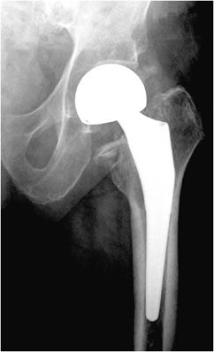
Figure 10-1. Bipolar prosthesis. AP view of the bipolar right hemiarthroplasty, with separate acetabular cup. Note the radiolucent native articular cartilage surface.
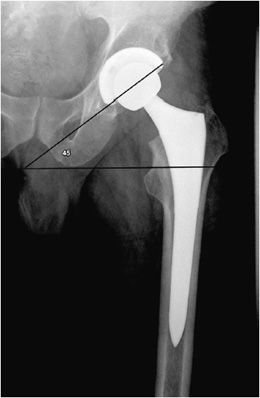
Figure 10-2. Total hip replacement. AP view of the total hip arthroplasty, consisting of both the femoral and acetabular components. The polyethylene liner separating the acetabular cup from the femoral head is radiolucent. The AP view best illustrates the angle of inclination (normal between 30 and 55°).
The postoperative radiograph of the hip includes AP and lateral view including the entire femoral stem and acetabular component. The AP film is used to measure the angle of inclination that is optimal at 30–55° (Figure 10-2), and the lateral film is used to measure the angle of anteversion that is optimal around 15°.1,2 The femoral component should be either parallel to the femoral shaft or in slight valgus. Varus alignment increases the risk of stem migration, which can result in periprosthetic fractures (Figure 10-3). With varus alignment, the lateral femoral cortex is most often injured. Regardless of the location of the periprosthetic fracture, revision to a longer-stemmed revision prosthesis is often needed. The femoral component should also be symmetric in the center of the acetabular component. Smooth 2 mm or less radiolucent lines at the bone–cement interface can be normal if not progressive. Subsidence (sinking in of the prosthesis) of less than 2 mm is also within normal limits.4
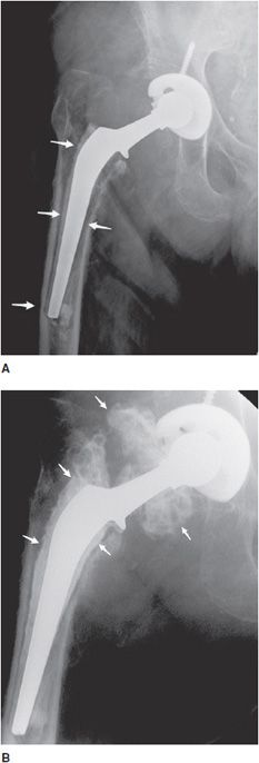
Figure 10-3. Loose stem total hip prosthesis. (A) AP radiograph shows significant femoral stem loosening (arrows) and varus alignment of the femoral stem tip. (B) Arthrogram of the hip reveals contrast accumulation in between the bone and cement interface indicating loosening of the prosthesis stem (arrows).
KNEE PROSTHESES
Most knee replacements are total knee replacements involving resurfacing of the femoral condyle and the tibial plateau (Figure 10-4). The patella may either be simply resurfaced, or a patellar prosthesis (e.g., a button) may be attached (Figure 10-4C). The patellar and tibial components may be cemented or cementless. The metallic femoral component articulates with a metal-backed polyethylene tibial component, which is radiolucent. Tricompartmental knee prostheses can further be subdivided into posterior cruciate ligament (PCL) sparing or sacrificing prostheses. PCL sparing prostheses are most commonly performed and have slightly improved gait. To differentiate between the two types of prostheses, a large box is seen in the femoral component on the lateral film that articulates with the polyethylene in the tibial tray that provides posterior stability.1,2
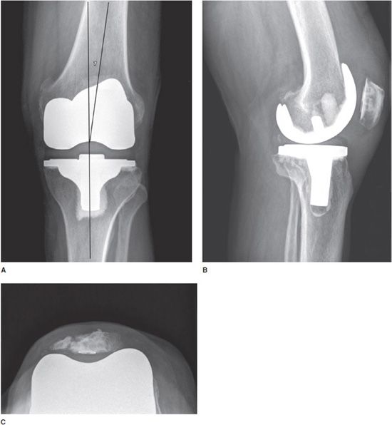
Figure 10-4. Total knee arthroplasty (TKA). AP (A), lateral (B), and sunrise (C) views of TKAs show cemented tibial and uncemented femoral components. In all images, the polyethylene component is radiolucent and cannot be seen readily on radiograph. (A) The femorotibial component should be aligned in 4–7)° of valgus, and the articular surface of the tibial component should be aligned parallel to the ground. TKAs may involve simple patellar resurfacing (B) or placement of a patellar button (C). Note in (C), patellar resurfacing and fracture of the patella are seen.
Standing AP (Figure 10-4A), lateral (Figure 10-4B), and patellar views (Figure 10-4C) are obtained when evaluating the postoperative knee. The optimal alignment for the femorotibial component is 4–7° valgus in the AP projection (Figure 10-4A) and neutral to minimal flexion on the lateral radiograph (Figure 10-4B).2 In addition, the articular surface of the tibial component of the prosthesis should be parallel to the ground on the standing views (Figure 10-4A). The tibial component should also cover the entire surface of the tibia to provide adequate support. The femoral component should be 90° to the long axis of the femoral shaft on the lateral view.1
Unicompartmental knee prostheses have been used in younger patients with isolated medial or lateral compartment arthritis (Figure 10-5). In these cases, a single femoral condyle and its tibial articulating surfaces are resurfaced. Unicompartmental patellar prostheses have been shown to result in suboptimal outcomes and are not routinely used.
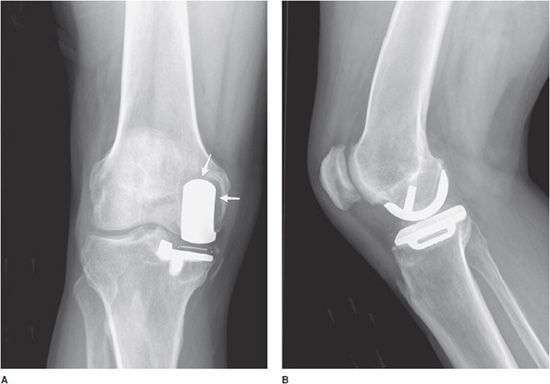
Figure 10-5. Unicompartmental knee arthroplasty (UKA). AP (A) and lateral (B) radiographs of UKA. The radiopaque line between the femoral and tibial components seen on the AP view (A) corresponds to a metallic marker within the polyethylene component. Additionally, on the AP view (A), note the periprosthetic lucency (arrows) that represents hardware loosening. There is linear soft tissue calcification incidentally noted near the medial tibial condyle.
ANKLE PROSTHESES
The ankle is a complex joint, and success rate for joint replacement has been suboptimal. The lack of success is likely due to inability to duplicate the normal mechanics of the ankle joint and inability to restore the stabilizing effect of the ligaments. Although second-generation ankle prostheses have had better outcomes than first-generation prostheses, ankle arthrodesis remains the treatment of choice in managing the painful ankle joint.
SHOULDER PROSTHESES
Three types of surgeries exist for shoulder replacement: hemiarthroplasty (Figure 10-6), total shoulder arthroplasty (Figure 10-7), and reverse shoulder arthroplasty (Figure 10-8). A shoulder hemiarthroplasty is used in cases such as severe proximal humeral fractures and severe rotator cuff tear where the patient still possesses a normal glenoid. The humeral component may be cemented or noncemented, and articulate with the native glenoid. A total shoulder arthroplasty, usually performed in severe glenohumeral osteoarthritis, has a metal or polyethylene-backed glenoid component (Figure 10-7).3 The reverse shoulder arthroplasty is performed in patients with a nonfunctioning rotator cuff due to massive rotator cuff tear (Figure 10-8). In this case, the ball-shaped glenoid component aligns with the cup of the humeral component. The cup of the humeral component is connected to the stem portion of the prosthesis. Because these designs are held in place by the surrounding rotator cuff, they are either semiconstrained or unconstrained and are more prone to dislocation.1
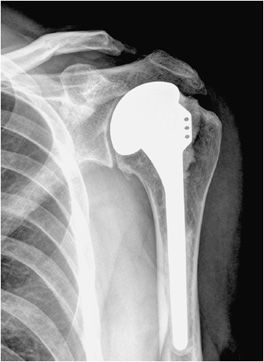
Figure 10-6. Shoulder hemiarthroplasty. AP radiograph shows shoulder hemiarthroplasty. Note the absence of any glenoid components. Also note that the superior aspect of the prosthetic head lies above the greater tuberosity; this positioning helps prevent subacromial impingement.
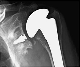
Figure 10-7. Total shoulder arthroplasty. AP radiograph shows total shoulder arthroplasty. Note the glenoid component contains radiopaque and radiolucent parts. Also note minimal lucency surrounding the radiopaque glenoid component suggestive of loosening.
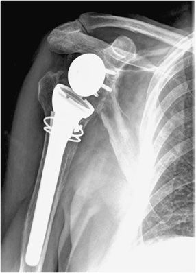
Figure 10-8. Reverse total shoulder arthroplasty. AP view shows reverse total shoulder arthroplasty. Note the medialized center of rotation, which allows the deltoid muscle to substitute for the deficient rotator cuff musculature to facilitate shoulder abduction.
Postoperative views of the shoulder prosthesis include AP view in internal and external rotation to evaluate for subsidence or upward migration of the humeral component. In a patient with an intact rotator cuff, impingement occurs if the most superior aspect of the prosthesis lies below the level of the superior tip of the greater tuberosity. Trans-scapular Y or axillary views are also obtained to assess for dislocation.
ELBOW PROSTHESES
Total elbow prostheses consist of both the humeral and ulnar components. Elbow prostheses can be categorized by design, either as linked or nonlinked. Linked elbow prostheses can be likened to constrained prostheses, whereas nonlinked elbow prostheses can be likened to nonconstrained prostheses. The linked portions have a rigid hinge that connects the humeral component to the ulnar component (Figure 10-9). Loosening, especially at the humeral component, is a major problem. The unlinked prostheses have stemmed ulnar and humeral components that articulate via an interposed polyethylene liner. In this case, stability is provided by the adjacent muscles, and intact tendons and ligaments. Finally, radial head prostheses may be performed in cases of comminuted radial head fractures (Figure 10-10).
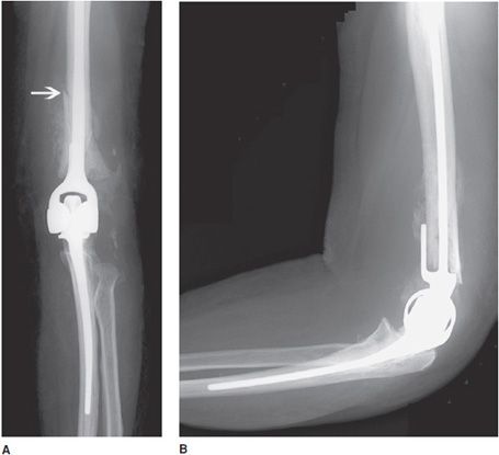
Figure 10-9. Constrained left total elbow prosthesis. AP (A) and lateral (B) radiographs of constrained left total elbow prosthesis. Hinged prostheses often suffer from loosening, as exhibited by the periprosthetic lucency surrounding the humeral component that has led to periprosthetic fracture of the distal humeral shaft (arrow).
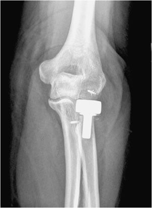
Figure 10-10. Elbow radial head prosthesis. AP view of the right elbow illustrating radial head prosthesis.
WRIST AND HAND PROSTHESES
Wrist arthroplasty is usually performed in patients with rheumatoid arthritis or severe osteoarthritis. For replacement of individual carpal bones due to avascular necrosis or trauma, Silastic prostheses have been used. The metacarpophalangeal and interphalangeal joints are commonly performed arthroplasties in patients with severe rheumatoid arthritis. There are no clear indications in management, and in most cases management often trends toward partial or total arthrodesis of the wrist and the hand.
JOINT PROSTHETIC COMPLICATIONS
Bone fractures typically occur within the early postoperative period in patients with poor bone stock such as osteoporotic patients. In the hip, excessive varus alignment of the femoral stem will eventually predispose to early periprosthetic fracture (Figure 10-3A), requiring a long-stem revision procedure. Fractures of the prosthesis or cement are usually delayed complications secondary to long-term repetitive stress. Loosening is a common delayed complication shared by all prostheses (Figures 10-3A,B, 10-5A, and 10-11). Repetitive mechanical stresses can cause loosening at the cement–bone, prosthesis–bone and cement–prosthesis interfaces. Lucency that is less than 2 mm in width and nonprogressive on follow-up radiographs is considered normal. Progression of lucency greater than 2 mm or development of new, irregular areas of lucency is likely secondary to loosening (Figures 10-3A,B, 10-5A, and 10-11).4 It is always important to have prior films available in addition to short-term follow-up films to assess progression of loosening. In the hip, subsidence of the femoral portion of the prosthesis that is greater than 5 mm is also indicative of loosening. Subsidence of the acetabular component will also result in protrusio acetabuli, or migration of the prosthesis into the pelvic cavity. Other signs of loosening in the hip prosthesis include cement fracture and sclerosis (pedestal formation) at the tip of the prosthesis.4
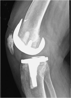
Figure 10-11. Loose femoral component of total knee arthroplasty (TKA). Lateral view of the TKA illustrating loosening of the anterior aspect of femoral component at the site of the bone–metal interface (arrow), as evidenced by the lucency between the femoral cortex and prosthesis.
Infection is a serious delayed complication of any joint replacement. There is considerable overlap in differentiating infection from loosening. Additional clinical information, including laboratory analysis, is needed to assess the likelihood of infection. Radiographically, the presence of irregular periprosthetic lucency, periosteal reaction, and bone destruction is suggestive of infection rather than loosening (Figure 10-12A,B). Focal areas of lucency are more suggestive of loosening than the generalized lucency seen in infection. Additional signs of infection include soft tissue swelling, large joint effusion (Figure 10-12B), and abscess formation. Joint aspiration is the most definitive technique to diagnose septic arthritis. Arthrography can also be used to diagnose both loosening and infection. Initially, the joint is aspirated for laboratory analysis. Next, iodinated contrast is injected into the joint. Contrast accumulation around in the region of periprosthetic lucency is suggestive of loosening (Figure 10-3B) or infection. Antibiotic-laced cement may be used after removal of infected prosthesis (Figure 10-13). Other methods to diagnose prosthetic infection include ultrasound-guided joint fluid aspiration and nuclear scintigraphy.5
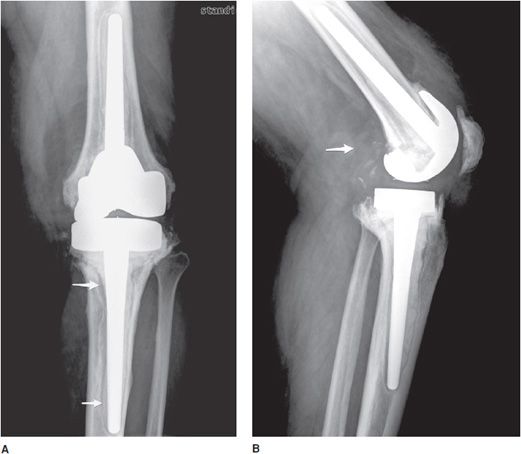
Figure 10-12. Infected total knee arthroplasty (TKA). AP (A) and lateral (B) views of the TKAs. (A) Both the femoral and tibial components of the TKA exhibit irregular periprosthetic lucency (arrows), suggestive of infection. (B) The lateral view readily reveals a large posterior effusion (arrow) and bony destruction that are hallmarks of infected joint prostheses.
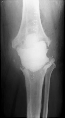
Figure 10-13. Infected total knee arthroplasty (TKA) with antibiotic cement spacer. AP view of the infected TKA with antibiotic cement spacer. Infected TKAs are often revised in a staged fashion: first, the infected TKA is removed and an antibiotic spacer is placed as illustrated, and subsequently once the infection has been eradicated with irrigation, debridement and antibiotics, the revision surgery takes place.
Another relatively common complication of joint replacement is particle disease that is a host inflammatory osteolytic response, which occurs after shedding of portions of the prosthesis (Figure 10-14). It is usually a response to the radiolucent polyethylene liner or methylmethacrylate. Although they occur more commonly in hip prostheses, particle disease can also occur in any other prostheses. Particle disease usually manifests as multiple well-defined lucencies that do not conform to the shape of the prosthesis (Figure 10-14). Additional foci of endosteal scalloping may also be seen. Unlike infection, a periosteal reaction is not seen in cases of particle disease. Along the same lines, polyethylene wear is a common entity seen in both the hip and knee prosthesis (Figure 10-15).
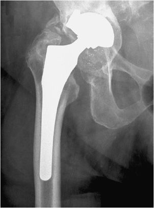
Figure 10-14. Aggressive granulomatosis (particle disease) in total hip arthroplasty (THA). AP view of the left hip arthroplasty with particle disease, as evidenced by lucencies around the prosthesis components and multiple metallic particles in the joint space.
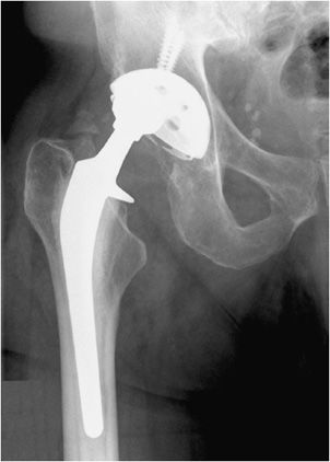
Figure 10-15. Polyethylene liner wear and displacement. AP view of the right hip. The femoral head of the prosthesis is not centered in the acetabular cup due to wear and displacement of the polyethylene liner.
Dislocation or subluxation may occur in either the early or late postoperative period. This is a greater problem in semiconstrained or nonconstrained arthroplasties such as the shoulder or the elbow if the surrounding muscles, tendons, and ligaments do not have the adequate strength to prevent subluxation and dislocation. Another complication seen in various joint replacements is heterotopic ossification seen around the periprosthetic region. Heterotopic ossification can also be seen with other types of hardware as well (Figure 10-16). Patients at higher risk of heterotopic ossification include patients with a history of ankylosing spondylitis, diffuse idiopathic skeletal hyperostosis (DISH), and hypertrophic osteoarthritis.1 In advanced cases, heterotopic ossification can limit mobility of the joint and may eventually cause joint fusion.
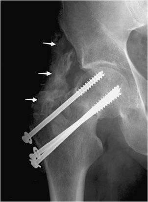
Figure 10-16. Heterotopic ossification around the hip joint. AP view of the right hip demonstrating cannulated screw fixation of femoral neck fracture, with extensive heterotopic ossification (arrows) about the greater trochanter. Heterotopic ossification in this region predictably results in significant deficits of hip flexion and abduction.
SPINAL FUSION
Spinal fixation procedures are commonly encountered in today’s radiologic practice. The most common indication for spinal surgery today is degenerative disk disease. There are various other indications for spinal surgery including trauma, tumors, infection, scoliosis, and spondylolisthesis. The goal of spinal fixation devices is to restore anatomic alignment; stabilize the bone during fusion; and replace bone defects in cases of trauma, tumor, or infection. The same principles that apply to other joints also apply to the spine. Fusion of a diseased joint will eliminate pain by eliminating the motion between the painful joint, such as severely diseased disks within the lumbar spine.6 It usually takes 6–9 months for solid fusion to be seen radiographically. The other important concept to realize is that the spinal hardware is used to provide temporary fixation and stability by immobilizing the bone. The function of the hardware is complete when osseous fusion occurs. Most intact implants are generally left in place after bony fusion due to the morbidity involved in recurrent spinal surgery. This section will discuss the procedures and range of hardware devices used in spinal fixation. The postoperative complications will then be discussed.
SPINAL INSTRUMENTATION
Although many spinal fusion instrumentation systems exist, the basic components of each system can be classified into a few general categories. Interpedicular screws are connected either by rods or plates that span single or multiple vertebral body segments (Figures 10-17 to 10-22). Plates are also commonly used in conjunction with cortical screws in anterior fusion of the cervical spine (Figure 10-17A,B). There are various sizes of plates that can be used for both the anterior and posterior fusion procedures. Rods are used to provide stability over short or long segments (Figures 10-17 to 10-22). A common example is the Harrington rod used for scoliosis of the spine. Harrington rods help provide distraction along the concavity and compression forces across the convexity in the treatment of scoliosis. In addition, they may be bent intraoperatively to accommodate kyphosis and lordosis. Rods can be attached to the spine by pedicle screws, wires, or cables. Disk spacers are inserted into the intervertebral disk space after the diseased disk is removed (Figures 10-17A,B and 10-19A,B). They are made of titanium or radiolucent material such as polyether ether ketone (PEEK). Surrounding bone graft material is also used surrounding the disk spacer to provide additional stability. Bone graft material is also used within the posterior elements in posterior spinal fusion to provide additional stability. Finally, corpectomy (vertebral body replacement) may be necessary after major trauma or destruction of the vertebral body by tumor or infection. Usually, the vertebral body is replaced by an expandable hollow cylinder packed with bone graft material or cement.6,7
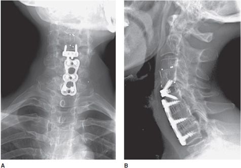
Figure 10-17. Anterior cervical fusion. AP (A) and lateral (B) radiographs of cervical fusion instrumentation show anterior cervical fusion of C4-5 and C5-7 via plates and vertebral body screws. The radiopaque vertical lines between the fused vertebral bodies represent the borders of each intervertebral disk spacer. These lines represent embedded metallic markers in each intervertebral spacer that aid in detecting migration of spacers on follow-up examinations.
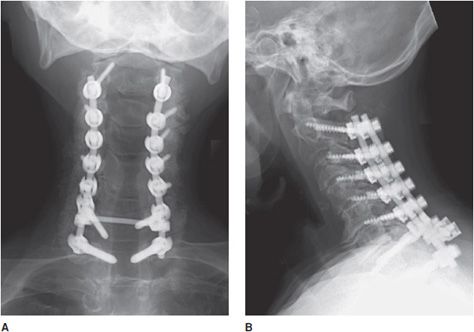
Figure 10-18. Posterior cervical fusion. AP (A) and lateral (B) radiographs of the cervical fusion instrumentation show posterior cervical fusion of C2-T1 with pedicle screws and rods. On the lateral view (B), intervertebral bone graft has incorporated, resulting in stable fusion of adjacent vertebral bodies.
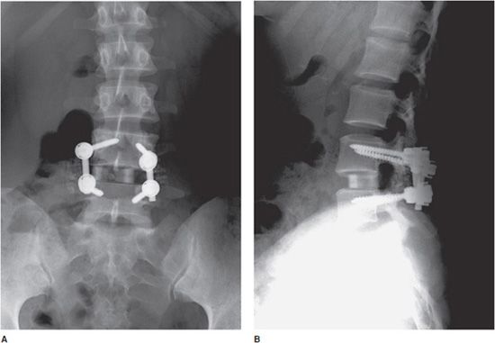
Figure 10-19. Lumbar spinal fusion with vertebral screws and rods, and intradiscal bone graft. AP (A) and lateral (B) views of the lumbar spine, demonstrating posterior interbody fusion of L4-L5 with intervertebral disk spacer bone graft.
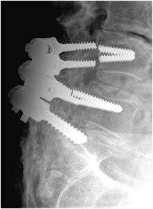
Figure 10-20. Broken pedicular screws. Lateral radiograph of the lumbar spine shows L4-S1 posterior fusion via rods and pedicle screws, exhibiting breakage of the L4 and L5 pedicle screws within the pedicle.
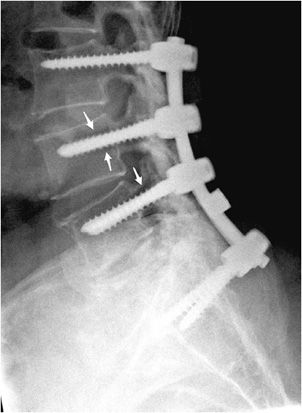
Figure 10-21. Loose pedicular screws. Lateral radiograph of the lumbar spine shows L3-S1 posterior fusion with rods and pedicle screws, exhibiting lucency surrounding the L4 and L5 screw threads (arrows) suggestive of loosening.
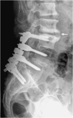
Figure 10-22. Lumbar fusion with adjacent degenerative disc stress and disease. Lateral radiograph of the lumbar spine shows L3-S1 posterior fusion via rods and pedicle screws, with large anterior marginal osteophyte seen at L2-L3 (arrow) with marked endplate subchondral sclerosis indicative of vertebral body degenerative changes and discogenic sclerosis as a result of abnormal stress at the site of the fused and unfused segments.
SURGICAL APPROACHES
Surgical approaches to the spine can be generally divided into the anterior and posterior approaches. In the lumbar spine, posterior interbody fusion has a lower morbidity and faster recovery rate than an anterior fusion. Posterior lumbar spinal fusion is commonly used in the treatment of degenerative disk disease, infection, and spondylolisthesis. Bilateral laminectomies are first performed for spinal decompression. Bone grafts are placed within the posterior elements to facilitate osseous fusion. Discectomy is then performed with intervertebral body disk spacers and surrounding bone graft placement. Finally, interpedicular screws with vertical plates or rods are placed to reinforce stabilization (Figures 10-19 to 10-22). Another modified type of posterior approach is the transforaminal fusion that leaves the midline posterior structures intact. In this case, a partial facetectomy is performed to gain access to the disk space for discectomy, bone graft placement, and subsequent vertebral body fusion.7
Alternatively, an anterior fusion can be performed, which allows for better access to the disk space when performing discectomy and vertebral body fusion. In the cervical spine, the anterior approach to fusion (Figure 10-17A,B) is usually performed for patients with painful herniated disks. It is the preferred method due to the risk of cord manipulation from a posterior approach, as well as the risk to vital structures such as the trachea, the esophagus, the lungs, and the carotid artery.8 First, the herniated portion of the disk or the entire disk is removed. Next, bone graft is placed to facilitate intervertebral body fusion, with anterior plate and screws fixation for further stability. Finally, spinal corpectomy is performed in patients with history of spinal fracture, tumor, infection or severe degenerative disk disease, all of which may result in compression of the central canal and/or nerve roots. An anterior or anterolateral approach is used. The disease or damaged vertebral bone is first removed. The superior and inferior disks are also removed, and bone graft is placed in place of the removed vertebral body, which results in fusion of the adjacent vertebral bodies. Side plates and screws are used to reinforce the fusion.
POSTOPERATIVE EVALUATION AND COMPLICATIONS
AP and lateral radiographs of the spine are necessary for postoperative evaluation. In certain cases, oblique images may be ordered as well. Additional flexion and extension views aid with assessment of spinal stability. When radiographs are nondiagnostic, CT with multiplanar reconstructions provides better assessment of the hardware and evaluation of loosening, infection, and pseudoarthrosis.
Early postoperative complications include postoperative hematoma, infection, and meningocele formation. In evaluating transpedicular screws, it is important that they do not breach the pedicle and cause damage to the nerve roots that course along the pedicle.9 In addition, the tip of the vertebral body screw must not breach the anterior cortex. Alternatively, anteriorly placed screws may penetrate the posterior cortex and cause impingement on the cord. Intervertebral spacers and bone grafts can also herniate anteriorly or posteriorly and cause neurologic compromise.
In terms of spinal surgical hardware, complications include fracture, migration, and dislodgment of the implant. Fractures of hardware components include broken screws (Figure 10-20), broken wires, and fractures of the rods. Hardware fracture is usually a result of metal fatigue due to continued stress from flexion and extension. This causes motion and instability of the fusion with subsequent formation of a pseudoarthrosis, which represents fibrous rather than osseous union of the fusion.6,8 This will in turn increase the likelihood of loosening and hardware fracture. Hardware instability and motion will also cause bony resorption and loosening around the screws and other implants (Figure 10-21). An important risk factor for loosening is osteoporosis, as it is difficult for the screw to obtain purchase in an osteoporotic vertebral body.
Infection is an uncommon complication that usually presents with irregular progressive lucency and destruction surrounding the implant. An associated discitis/osteomyelitis may be present with destruction and collapse of the infected disk space. MRI, nuclear medicine scintigraphy with WBC scan, and possibly CT-guided aspiration may be needed for further characterization of the infection.6 One other complication of spinal fusion must be noted: although fusion may be successful, it will eventually cause increased stress at levels above and below the level of surgical fixation. Facet arthritis and degenerative disk and facet disease are common above and below the level of the fusion (Figure 10-22).8 Furthermore, fused bones are less mobile, making the adjacent vertebral bodies more prone to fracture in cases of trauma.
FRACTURE FIXATION
In this section, the nonoperative and operative methods of fracture fixation including the instrumentation, approaches, and complications will be discussed. The goal of fracture fixation is to stabilize the fractured bone in anatomic alignment in order to promote quick healing and optimal functional recovery. To understand fracture fixation, two concepts of bone healing must first be understood: callus healing and callus-free bone healing. Bone healing via callus formation is also referred to as indirect fracture healing. It occurs in unstable or relatively stable mechanical conditions such as bone immobilized by a cast or a splint, or via intramedullary nail fixation or bridging plates that simply span the fracture site without screw fixation directly adjacent to the fracture site. The healing process with callus formation can be divided into four stages. Initially, there is formation of hematoma and a host inflammatory response surrounding the fracture site. Next, soft callus develops at 2–3 weeks followed by hard callus formation at 2–4 months. Radiographically, solid callus is seen at this time bridging the fracture site. Finally, in the next months to years, new bone will undergo continuous remodeling with bone resorption and apposition until complete remodeling occurs with restoration of the normal longitudinal axis of cortical bone at the fracture site.
However, when a fracture is surgically reduced by plates and screws, fractures heal without callus formation. This type of fracture healing is often referred to as “direct” fracture healing. In this case, there is a very small gap between the fracture fragments, and fracture healing is initiated by the Haversian system of remodeling. The Haversian system is the functional unit of cortical bone. Cortical bone is made out of multiple layers of lamellar bone with a layer of osteoclasts at the tip. The osteoclasts function to resorb the end of the fracture, while osteoblasts form new bone behind the osteoclasts, thus creating numerous microscopic bony bridges across the fracture site. Healing without callus formation is the underlying mechanism for internal fixation and is advantageous due to the significantly decreased healing time.1
TECHNIQUES IN FRACTURE FIXATION
The first decision by the orthopedic surgeon is whether open or closed reduction of the fracture is necessary. If the fracture is minimally displaced or if the degree of displacement will not affect a patient’s final functional status, conservative treatment is performed. The surgeon may first perform closed manipulative reduction. In this method, the fracture fragments are manipulated through the soft tissues and restored to as near as normal anatomical position as possible. External immobilization devices can then be used for temporary immobilization or for definitive treatment. External immobilization comes in the form of external slings, splints, or casts. After immobilization, whether following operative or nonoperative reduction, close watch must be kept for swelling in a close fitting cast or splint as it may cause impairment to the circulation and vascular comprise to the distal part of that limb, possibly resulting in a compartment syndrome. Conversely, fractures of certain anatomical sites such as ribs, scapula, and clavicle need not be immobilized as they will heal well without immobilization.10
In certain fractures, such as fractures of the femoral shaft or distal humeral shaft, the elastic pull of the muscles tends to cause overlap of the fracture fragments. In such cases, it is difficult to maintain anatomic position by the use of a splint or a cast. As a result, surgical pinning or wiring is performed, such as pinning the distal femur with attachment to a traction device in order to counteract the weight of the pull of the muscles and subsequent sustained traction on the distal fracture fragment. In the distal femur, complications of traction pinning include damage to the quadriceps and surrounding neurovascular structures.
Internal fixation is the method of choice when acceptable alignment is not possible by splinting alone. Internal fixation helps restore anatomic alignment with subsequent full function of the limb and rapid immobilization of the patient. The devices used for external fixation fall under several categories, which will be discussed in turn.
Screws are the most common orthopedic devices used in fracture fixation. Two generalized categories exist. Cortical screws are fully threaded and tend to have finer threads. They are designed to anchor into cortical bone. Cancellous screws, however, are usually partially threaded, and have coarser threads that help anchor into soft medullary bone. Complications of screws include loosening, fracture, and migration (Figures 10-23 to 10-27). Progressive lucency around a screw on follow-up radiographs is indicative of loosening.
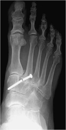
Figure 10-23. Broken screw. AP view of the right foot, illustrating breakage of Lisfranc joint screw.
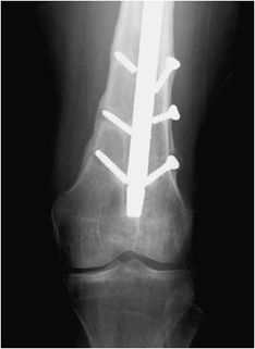
Figure 10-24. Multiple fractures of interlocking screws. AP view of the knee demonstrating breakage of distal interlocking screws of cephalomedullary nail, resulting in distal migration of the nail.
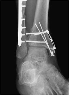
Figure 10-25. Breakage of syndesmotic screws. Mortise view of the right ankle depicting breakage of syndesmotic screws.
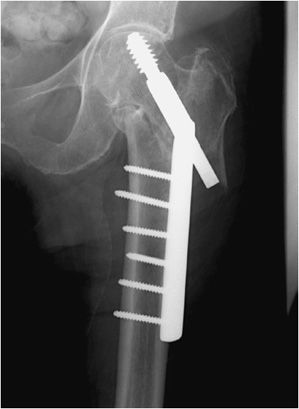
Figure 10-26. Migration of dynamic hip screw. AP view of the left hip demonstrating superolateral migration of dynamic hip screw. Note telescoping and posterior retraction of the dynamic hip screw.
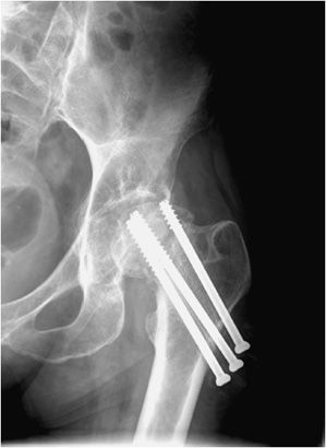
Figure 10-27. Superior migration of cannulated screw. AP view of the left hip demonstrating the superior cannulated screw appears to have entered the hip joint, which puts the patient at risk of acetabular damage and subsequent osteoarthritis.
Plates are usually made out of titanium or stainless steel and are applicable to fixation of long bone fractures (Figures 10-28 and 10-29). Six to eight screws are usually fixed to a plate by threaded holes. It is important to note that there is mobility between the fracture fragments when under a stress load. This is eliminated with usage of a special type of screw, the interfragmentary screw. The interfragmentary screw is a screw that crosses the fracture line (Figure 10-29), ideally perpendicular to the fracture line. In crossing the fracture line, the screw is able to compress the fracture fragments together. This helps abolish motion at the fracture site and promotes faster healing without callus formation. In successful internal fixation, there is gradual loss of the lucency at the fracture interface. Any gap widening or fracture of the plate is a symptom of instability (Figures 10-30 and 10-31). Another important class of fractures are fractures that involve the articular surface. Intra-articular fractures require very precise anatomic reduction in near-perfect anatomic alignment to avoid development of callus formation, as this will increase the chance of developing early post-traumatic osteoarthritis.1,10
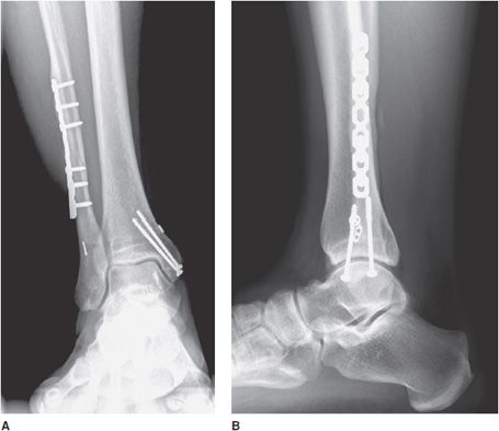
Figure 10-28. Ankle fracture with plate and screw fixations. AP (A) and lateral (B) views of the right ankle joint, exhibiting bridge plate fixation of oblique fibular fracture with malleolar screw fixation of medial malleolus fracture.
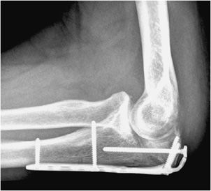
Figure 10-29. Plate and screw fixation of olecranon fracture. Plate and screw fixation of olecranon fracture with axially oriented interfragmentary screw traversing fracture site.
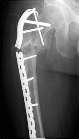
Figure 10-30. Fracture of the femoral contoured plate. Fracture of contoured lateral femoral plate with associated subtrochanteric fracture through fracture callus with associated varus malalignment and nonunion.
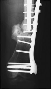
Figure 10-31. Fracture of cerclage wires and misplacement of screw at fracture site. Fracture nonunion leading to instability and subsequent hardware failure. There is screw breakage and rupture of proximal cerclage wires with resultant plate separation from cortical bone. Note one of the screws was erroneously placed in the fracture site.
Complex pelvic and acetabular fractures require the use of reconstruction plates for fixation. These plates are very malleable and can be shaped to stabilize complex fractures involved in the pelvis. Another well-known plate and screw apparatus is the dynamic hip screw used to treat intertrochanteric fractures (Figure 10-26). Initially a side plate is affixed to the distal femur and attached with multiple cortical screws. The side plate consists of a hollow barrel proximally, in which a screw is inserted transfixing the femoral head and neck. The plate has a hole toward the proximal end, in which a screw may be inserted that ends in the femoral head. The dynamic hip screw side plate and screw, like any other hardware, are subject to fracture migration and loosening (Figure 10-26). Given the large surface area contact of such side plates with the cortex, cortical blood supply may be compromised, which may result in nonunion or delayed union.
Intramedullary nails are used in the treatment of long bone fractures usually in the middiaphyseal region (Figures 10-32 and 10-33). Intramedullary nails are commonly used in tibial and femoral fractures (specifically, intertrochanteric fractures). These surgeries are usually performed with minimal tissue exposure and may be performed in retrograde or anterograde fashion. Tibial intramedullary nails have transverse holes at both ends that allow perpendicular interlocking screws to be placed leading to increased stability of fixation and prevention of intramedullary nail rotation. Femoral intramedullary nails typically have distal interlocking screws, as well as a transverse hole at the proximal end in which a cephalomedullary screw may be inserted that ends in the femoral head. Potential complications of intramedullary nail placement are violation of the joint space and damage to the internal cortical blood supply that can subsequently increase the rate of infection. For fixation of femoral neck fractures, cannulated screws are often used (Figure 10-27). These screws have a hollow core, which allows them to be inserted percutaneously over a guide wire, with less risk to the blood supply of the femoral head. Three screws are typically used to achieve fixation, with two screws placed inferiorly and one placed superiorly.11,12
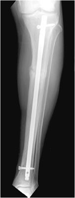
Figure 10-32. Intramedullary rod and locking screws. Tibial intramedullary nail with one proximal and one distal interlocking screw, transfixing a proximal transverse tibial fracture. Note the formation of early bridging callus.
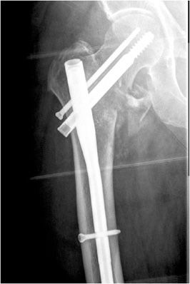
Figure 10-33. Femoral cephalomedullary nail. Cephalomedullary femoral nail with distal interlocking screws.
Wires are commonly used as an alternative to screws for fixation of small osseous fracture fragments. Multiple thin-diameter Kirschner wires (also known as K-wires) are sometimes used in stabilizing comminuted intra-articular distal radial fractures (Figure 10-34) as well as many types of phalangeal and metacarpal fractures. Cerclage wires are another common type of wire used in encircling and fixation of fracture fragments. They are commonly used for reinforcement in revision arthroplasties due to periprosthetic fractures in order to provide additional support. Finally, tension band placement is commonly used in the fixation of olecranon and patellar fractures. In this method, cerclage wires are used to fixate the two fracture fragments and are stabilized by additional Kirschner wires or screws. When placed correctly, the wires convert the tensile forces of the muscle on the fracture fragments into a compressive force that promote fracture healing.10–12
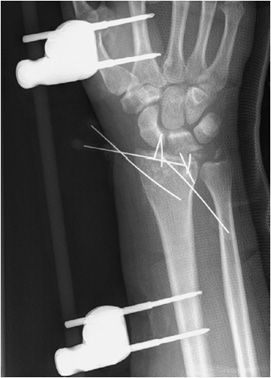
Figure 10-34. External fixator and K-wire fixation of distal radial fracture. AP view of the right wrist, demonstrating K-wire fixation of distal radius fracture with spanning external fixator in place.
The indications for external fixation include open fractures, periarticular fractures, and pediatric factures in which the growth plate is to be avoided. In open fractures, there is usually significant surrounding soft tissue injury, possible vascular compromise, and increased risk of infection. As a result, internal fixation is undesirable due to both increased damage to surrounding soft tissues and increased risk of infection with the use of internal plates and screws. External fixators are made of a combination of pins and rods that are placed percutaneously into the bone above and below the fracture site (Figure 10-34). These systems allow the easily adjustable compression of the bone fragments. A well-known type of external fixator is the Ilizarov frame that uses thin wires to secure the proximal and distal fracture fragments, with the wires then attached to an outside ring frame that are all lined and connected by adjustable rods.10 The Ilizarov device is used in the treatment of limb lengthening procedures as well as complex bone fractures. In external fixation, daily cleansing must be performed in order to keep the pin sites clean as infection could cause the pin sites to loosen and require their removal.
CONCLUSION
Various types of fracture hardware and fixation methods have been discussed. The type of fracture, anatomical site age, and comorbidities of the patient will dictate what approach the surgeon will have in treatment of the fracture. As with joint replacement, and spinal fixation, many similar complications apply including infection, loosening, and hardware fracture. It is important for the radiologist to have familiarity with the most common orthopedic procedures in order to better recognize complications involved with various procedures. As with other regions of the body, prior imaging and follow-up imaging, in addition with the clinical information is essential in helping to provide the correct diagnosis.
Related posts:
Stay updated, free articles. Join our Telegram channel

Full access? Get Clinical Tree


